
A Mobile Control Room
The acoustic characteristics of a vehicle body. The problems presented and their means of control. Loudspeaker design for specialised conditions.
It would seem appropriate in at least one chapter to try to go through an entire design process. This way it will be possible to get an idea of the typical problems that arise, and the means available to solve them. Furthermore, if a mobile recording vehicle is chosen as the object of the exercise, it will allow us to look at another set of circumstances that have not been discussed in earlier chapters. So, let us now look at the concept, design and construction of a multitrack mobile recording vehicle, designed by the author at the end of the twentieth century.
23.1 The Problems to be Solved
During the spring and summer of 1998, Portugal was presenting Expo’98, a world fair of the oceans. The enormity of this exercise was to occupy much of the country’s mobile recording and broadcast facilities, so the company Banzai Lda, which was engaged in many other recordings, decided to invest in a mobile sound recording vehicle in order to fulfil their own recording contracts.
The final decision to build a vehicle was only taken in early 1998, and the first recordings were to begin at the start of the following May. The three months available for the design and construction appeared to be too short to make an entirely new truck, so a search was made to find an existing vehicle that could be re-built to their specifications. They discovered that NOV, the Dutch broadcasting organisation, had a sound vehicle for sale, so one of Banzai’s owners went to Holland to see it. The truck appeared to be suitable for their needs, and it had the necessary infrastructure, but internally it needed to be totally rebuilt.
This was quite an interesting challenge, because the request came exactly at a time when 25 years earlier, the selfsame designer had been building the first of the Manor Mobiles, to which the construction and dimensions of the NOV truck were not too dissimilar. The problems were therefore known intimately, and it was a great opportunity to see if it would now be possible to deal with the limitations that had been so seemingly insoluble in the past. Monster vehicles were easier to deal with, but the mid-sized vehicles, with control rooms in the 5 to 6 m range, tended to be too small, the wrong shape, and too light from an acoustic point of view if a flat monitoring response was required.
The first Manor Mobile was built in 20 ft× 8 ft× 8 ft foot (6m × 2.4m × 2.4 m) freight container, and the Banzai vehicle had a working space only slightly smaller, as shown in Figure 23.1. Both vehicles were made principally from glass-reinforced plywood (GRP) with heavily damped plywood floors on steel beams. The basic response of this type of shell, driven from an end wall, is shown in Figure 23.2. The Manor container was fitted with a rear bulkhead having a door and cable housing, so that the truck could be used with its heavy container doors open, as shown in Figure 23.3. The walls and ceiling were lined with 13 mm plasterboard to improve their damping and sound isolation, but the sheer size of the then current equipment precluded the use of much space for any resonator boxes – the traditional method of ‘tuning’ a room in those days.
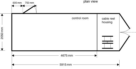
Figure 23.1 Available space after removal of original recording equipment
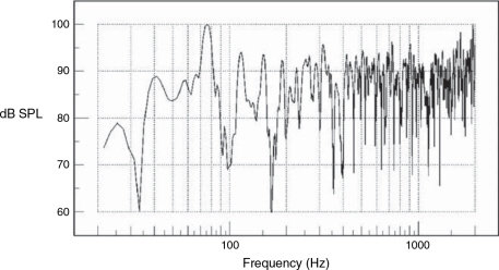
Figure 23.2 Simulated frequency response of bare shell (450 cm × 200 cm × 200 cm)
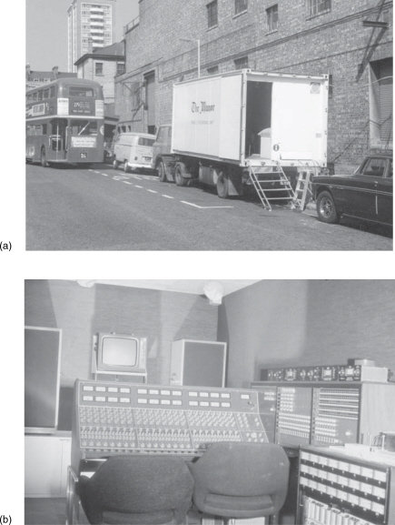
Figure 23.3 (a) The first Manor Mobile, in 1974, recording Queen at the Rainbow Theatre, London. The rear container doors are fully open, revealing the rear bulkhead and doorway. The huge fuel tank, beneath the trailer, was one of three, fitted during the 1973 oil crisis. The tanks gave the mobile a range from Oxford (its base in the UK) to the south of France, and back, without refuelling. Fuel was bought wherever available. (b) The inside of the vehicle, a week before going into operation in July 1973. On the right can be seen the world’s first Ampex MM1100 24-track tape recorder, bought by The Manor Mobile in the preceding January. The machine was a pre-production model, built in the Ampex laboratories, not the factory
The plasterboard/plywood walls did absorb some low frequencies, but they achieved much of their sound isolation by reflexion, so they tended to bounce a lot of energy around inside the room, creating the overall response shown in Figure 23.2. This was not ideal, by any stretch of the imagination, but the situation had been helped to some degree by the use of Tannoy Dual Concentric loudspeakers in Calrec/IMF transmission line cabinets. At least with these coaxial loudspeakers the ‘point source’ nature of the sound generation meant that most reflexions arrived at the listener with their phase and frequency responses intact. Loudspeakers with spacially separated drive units for different frequencies tend to produce reflexions where the different path lengths from the ear to the different drivers cause time and phase distortions to occur. Hence the ‘don’t lie your NS10s on their sides’ rule.
The Manor Mobile was lumpy in its low frequency response, but no more so than the other vehicles around at the time. However, the crew knew it well, and were largely able to compensate. This was a huge improvement on the situation during the designer’s early days with Pye Records, whose mobile unit without a control room in a vehicle had two Neve Series 80 consoles, each of which could be split in half for transport, or the two complete units could be joined together. It took four people to lift each section, and two people to lift each of the three sections of the ‘portable’ 3 M M56 8-track tape recorders. All this, together with the large Lockwood/Tannoy monitors, would be set up in the best available space for each recording: dressing rooms, offices, hallways and the like. Obviously, this meant that the monitoring conditions varied wildly, so apart from listening for noises or distortions, and perhaps assessing the relative musical balance of a section of instruments, not too much could be done in the way of judging the timbre of an instrument, especially at the lower frequencies.
Nevertheless, this situation did have its compensations, such as recording at the ‘Talk of the Town’ in London, where the only available ‘control room’ was the chorus girls’ changing room. During the various acts, they would come in, strip off, and change costumes. Concentration definitely suffered on such occasions.
Together with the monitoring variability, the great loss of time for rigging and de-rigging led Pye to build their first dedicated mobile vehicle in 1971, which went on the road just after the Rolling Stones mobile. It was immediately appreciated that this gave a new consistency in monitoring conditions, which, even if they were wrong, at least they were always the same. The crews could learn how to come to terms with their ‘wrongness’ which was something which was very difficult when portable equipment was set up in a different room for each recording venue. In fact, when The Manor Mobile bought the Pye mobile in 1974, not only was it up-dated and expanded, but it was refitted into a new vehicle, very similar to the first Manor Mobile. This was specifically done to try to ensure the closest match of monitoring conditions between the two. The crews therefore did not have to remember which truck they were in, or which mental compensation to make.
23.1.1 Electronic Control Limitations
The trucks worked well for recording purposes, and built an excellent reputation, but they were difficult environments for mixing, which was hard work and uninspiring. In fact, the trucks had never been intended for mixing, but the lack of 24-track studios in those days often left no other recourse. When Virgin built The Manor Studios with Tom Hidley, in 1975, its equalised Westlake monitors became the new reference. The Manor’s analysing equipment was taken into the trucks, and efforts were made to try to equalise the monitors, but it was simply not possible to achieve a flat response, the peaks and dips were too severe. Six decibels represents a four times power difference, so trying to correct a 6 dB response dip simply overloaded the amplifiers and loudspeakers (which were only rated at about 50 W, anyway) as it called for four times more power. Furthermore, no matter what equalisation was applied to the system, it always seemed to sound subjectively less natural, even if it did at times sound a little more uniform.
Of course, such efforts were futile. The majority of the response irregularities were caused by the reflexions in the room and the standing wave field. This was obvious from the fact that the low frequency character changed significantly as one walked around the room. Equalisation can only be used to deal with the minimum-phase problems, which are the response irregularities caused by driver roll-offs, the loading effects due to the proximity of room boundaries (not the reflexions themselves) and certain other response problems which are independent of listening positions. These, remember, are the effects that are superimposed on the acoustic signal at its time of generation. In these cases, correction of the amplitude response by equalisation will tend also to correct the phase and time responses.
However, non-minimum-phase problems are the ones such as those created by multiple reflexions, when the disturbance is caused by a mixing of the direct signal and time-shifted reflected energy. The arrival-time difference between the two signals produces comb filtering in the signal, as was shown in Figure 5.12. It is impossible to use conventional equalisers to compensate for such room effects, because any attempt to equalise the source signal to compensate for the combined signal will distort the frequency balance and the transient response of the direct signal. The integrity of the direct signal is superimportant, because by definition, until the first reflexion arrives, all rooms are anechoic, so the direct sound is the first sound heard, and it must be accurate.
Any equalisation of the direct sound will upset the transient response, and hence the wavefront of the signal. Anybody with the vaguest knowledge of how to get sounds on synthesisers will know well how important the attack is to the character of a sound. Quite remarkably, in the early 1970s, although these principles were known in academic circles (and obviously to Robert Moog), they were largely unknown in the recording world, and it had only been a few years earlier that Altec had brought out their ‘Acoustavoicing’ system, precisely to commit equalisation atrocities to monitor systems.
The warning bells started ringing for the recording staff of the Virgin Studios group in late 1978. Their new Townhouse Studios One and Two, in London, had very similar control rooms. Studio Two had the first large SSL mixing console in the UK, and therefore had its own specialist staff because this mixing console was very different in concept and operation compared to the usual mixing consoles of the day. The monitor systems in the two control rooms were identical, but the equalisation settings on the monitor equalisers were done by different people, and those settings were very different, as was the sound. This was despite the response of both rooms reading flat on a 27-band spectrum analyser. Chris Jenkins, Andy Wild, Steve Cater and Malcome Healey, the maintenance staff, brought this to the attention of the author, who was technical director of the Virgin Studios group, at that time. It seemed that they each had their own method for adjusting the equalisers. It was decided to zero all equalisers and have each of five people equalise each room separately. After taking notes of the settings, it was found that there were ten different filter responses, five for each room as adjusted by five different people. Now, one response in one location in one room from one signal source has one inverse response, not five! It was beginning to appear that it would have been possible to find dozens of different equaliser settings which would all read flat on a spectrum analyser, yet which would all produce different sounding monitor systems.
The situation was reported to Tom Hidley, who had designed the control rooms and monitor systems. He said to try to find the setting with the minimum of large excursions from zero; the smoothest curve. This concept was then applied as the general principle for any monitor equalisation in the Virgin Studios group, but the general confidence in the value of monitor equalisers had been shattered. Since the early 1980s, neither Tom Hidley nor the author, have used monitor equalisers, and this is the case for most designers these days.
It is true that equalisers are used almost de rigueur in film dubbing theatres, as they are part of the Dolby processors, but in cinemas they are used to create the smooth response for the greater part of the audience; they are not there for audiophile hi-fi reasons. These days, also, there is a proliferation of digitally adaptive room control systems, but they also have their limitations. First, the improvements at the ‘hot seat’, or in the chosen listening area, are gained at the expense of a poorer response in the rest of the room; see Figure 11.28. Second, many of them are based on 16 bit/48 K audio. In these days when so much is being done to introduce 24 bit/96 K audio, there would seem to be little purpose in trying to compare different high bit rate/high sampling rate recording systems via monitors that only have 16 bit/48 K resolution. It is on the monitoring system where one needs the most transparency of all, or judgements cannot be sensibly made.
23.1.2 Space Problems
Back to the situation with the Banzai mobile, their need was for a truck in which they could not only record, but also mix for television and CD releases. Hundreds of recordings in the old Manor Mobiles 1 and 2 had yielded much experience about the problems of the response in this type of basic shell, but, as has been discussed in the previous paragraphs, correcting this by monitor equalisation was out of the question. The Banzai truck was also seemingly too small to install sufficient conventional acoustic control systems, so how could a flat monitoring response be achieved? Fortunately, acoustic control measures had moved a long way forward from the use of the Helmholz resonator boxes of thirty years previously, but they are still area and depth dependent. In general, the surface area covered by the absorbers controls the amount of absorption for any given frequency, and the depth of the absorbers will determine the lowest frequencies that can be absorbed; although some trade-off is possible between the two.
Conventional acoustic control measures, as discussed in Section 13.7, tend to be wavelength dependent. They are not vehicle-size dependent. Tape One, in the late 1970s, had an excellent vehicle, but it was twice the size of the Manor Mobiles, and was almost half filled with acoustic control systems. In the case of the Banzai vehicle, such techniques (as they cannot be scaled) would have resulted in a truck that was all absorber – no control room! Clearly, this approach was out of the question. What was needed were solutions that could produce a respectably flat response in the control room, especially around the listening position, but also as uniform as possible elsewhere. Electronic solutions were not acceptable, and any acoustic solutions could not be space consuming to the extent of anything more than about 10% of the empty internal volume of the control room section of the vehicle. This was a challenge.
23.2 The Vehicle
After the purchase of the NOV truck by Banzai, it was taken from Holland to England, where Kustom Konstructions had been engaged to make the conversion. The truck was stripped out in London, then taken to Swanwick, near Southampton, where the carpentry work was carried out. The brief was to make a mobile control room that was suitable for recording and mixing, with the provision of 24-track analogue and 24-track digital recorders. Before the actual design of the vehicle began, the mixing console had been specified as a Euphonix CS3000, so a suitable space for this had to be allocated. There also needed to be space for limiters, compressors, effects processors, two television monitors, a jackfield, the analogue ‘audio tower’ for the mixing console, and a communications system.
Once stripped of its former recording equipment, the vehicle was left in the state previously shown in Figure 23.1. A heavy bulkhead separated the ‘control room’ from the cable reel housing. This was a heavy sandwich construction of GRP (glass-fibre reinforced plywood) and expanded polyurethane foam; in all approximately 10 cm in thickness. The bulkhead was well-damped, and provided excellent sound isolation between the two sections of the vehicle. It was decided to site the audio tower in the cable reel section, as the tower had seven fans and produced much noise and heat.
The Euphonix console was chosen primarily for the rapidity with which it could be re-configured: ideal for recording television programmes or concerts with several acts performing in rapid succession. An acoustic benefit was that the console itself was only a digital control surface, and was very slim. Slim-line consoles generally cause much less acoustic disturbance to any control room, but in very small rooms, large consoles can cause acoustic chaos, so the compact nature of the Euphonix was very well suited to the application under discussion, here.
The side walls of the vehicle were made from a sandwich of GRP, mineral wool and aluminium, the latter of which formed the outside surface. The ceiling was aluminium, with a 10 cm soft foam lining. The floor was double skinned, with cable ducts running within it, accessible by heavy hatches. Its top surface, which was entirely above the height of the wheels – thus providing a plane deck – was made of 30 mm plywood over a heavy framework of 10 cm ‘I’ section steel, with 15 mm plywood below. Underneath the floor were compartments for the air-conditioning equipment, a fuel-burning heater, power stabilisers, isolation transformers, and the batteries for the 24-volt reel-motors, standby lighting, and air-conditioning control.
23.3 Acoustic Discussion
The available space in the control room section was 2.05 m × 2.05 m × 4.67 m. There was a perforated wooden ceiling in the original vehicle, at a height of 2.05 m, above which, and below a lining of 10 cm foam rubber, ran air-conditioning ducts and the cables for the lighting systems. It was decided to adopt a ‘Non-Environment’ approach to the room design, which called for an absorbent ceiling. The open-cell foam was left in place, but the wooden ceiling was removed, and was replaced by ‘stretch’ fabric over an open wooden frame, into which new lights were mounted. The carpet was removed from the original floor, and was replaced by 1.5 cm of solid beech planking.
A monitor wall was constructed in front of the bulkhead, into which would be set the monitor loudspeakers, televisions, amplifiers, crossovers, console dynamics displays, communication systems, and the main electrical breaker panel. The finished wall is shown in Figure 23.4. It was made from a framework of 5 cm × 5 cm timber, faced with 13 mm plasterboard, a 5 kg/m2 deadsheet, and 19 mm MDF (medium density fibreboard). The television monitors were to be covered by a sheet of heavy, non-reflecting glass, so that there would be no cavities in the finished wall surface that could resonate or cause other acoustic disturbances. In these types of designs, the front wall acts as a baffle extension, and also as a means of providing life to the speech of the occupants within what could otherwise, in this case, be a rather uncomfortably dead acoustic in which to work for long periods. Three of the surfaces of the ‘Non-Environment’ were thus in place; the hard floor, the sturdy, reflective monitor wall and the absorbent ceiling. The question at this stage was how to achieve the maximum acoustic absorption on the remaining three surfaces, consistent with using the minimum amount of space for the treatments.
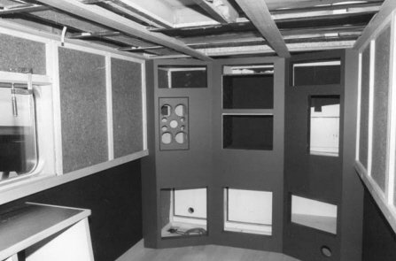
Figure 23.4 The basic framework of the Banzai monitor wall, with the lateral membrane absorbers also visible
As far as the internal acoustics are concerned, transmission through the walls could be considered equivalent to absorption within them, as in either case the energy would not be reflected back into the room. The basic shell provided isolation from inside to outside of about 30 dB, though somewhat less at the lower frequencies, and the internal acoustic control measures would be likely to add another 10 dB. Experience suggested that this would be adequate for most purposes, as mobile recording vehicles are rarely used in situations where they are, themselves, the most significant source of noise. A monitoring level of 90 dB SPL inside the vehicle would thus yield an SPL of around 50 dBA at a distance of three meters from the outside surfaces. Few recordings are likely to take place in areas where these sorts of leakage levels would cause offence, and in many cases the use of much higher internal levels (100 dB, or so) would also not be expected to cause any nuisance. After due consideration of the above figures, it was decided not to attempt any further isolation, because it would be space consuming. Furthermore, it could also be prejudicial to the internal acoustic control, by reflecting energy back into the listening area. Such had been the effect of the plasterboard lining in the first Manor Mobiles.
From an internal acoustics point of view, a lightweight, well-damped shell is desirable, as the whole surface area of three walls and a ceiling can be used for absorption. If some of the very low frequencies are allowed to re-radiate into the outside air, it effectively makes the room acoustically much bigger at low frequencies than it is physically. Remember, at around 30 Hz the threshold of hearing is about 65 dB SPL. Five to ten decibels up on this would be the minimum level that could provoke complaints in most countries, so only 20 dB of isolation at those frequencies would still allow monitoring at 95 dB SPL with impunity. With the monitors of the truck eventually being sited only about 120 cm from the listening position, 100 dB SPL at one metre was considered excruciatingly loud. Usually, there is little point in providing more isolation than necessary, because it also adds weight, which is another important consideration in a mobile recording vehicle. Of course, the minimum amount of energy reflected back into the vehicle is also important for minimising response disturbances.
The mixing console of 56 channels was only about 5 cm narrower than the inside of the vehicle, thus little treatment was possible on the lower halves of the walls unless the desk was to be ‘permanently’ built in. The lower one metre of each side wall was carpeted, though little of these surfaces would remain visible after the installation of equipment racks (wooden), and the digital and analogue tape recorders. The upper metre of each wall was kept free from any equipment or obstructions, and was treated as shown in Figure 23.5 with membrane absorbers. These consisted of 5 cm-deep, wooden frames, running back 250 cm from the monitor wall. The 5 cm space was then filled with an absorbent cotton waste felt, known as A1, which is self-extinguishing and has a density of around 60 kg/m3. The frame was then covered in PKB2, which is a 3.5 kg/m2 deadsheet, heat bonded to a felt similar to the A1. The whole system was then covered by a wooden frame, in turn covered in a stretch, Lycra material.
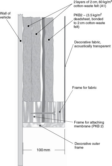
Figure 23.5 Side wall absorber system
This type of damped membrane absorber is quite effective at low frequencies, and the 2 cm felt surface is an effective absorber at high frequencies. Given their position in the vehicle, vis-à-vis the monitor loudspeakers, they receive most of the sound energy at near grazing incidences, which tends to augment their absorption. (See Figure 5.20.) Their primary purpose was to prevent early, lateral reflexions from disturbing the monitoring clarity, as well as to aid the overall low frequency control of the vehicle. The extra absorption that they provided would also improve the sound isolation through the side walls.
The remaining problem was what to do with the rear wall, which is usually the most troublesome surface in any control room.
23.3.1 Rear Wall Absorber
As can be seen from Figure 23.1, between the side entrance door and the front wall of the vehicle (the rear wall in terms of the control room layout), there exists a distance of about 60 cm. Ideally, from an acoustic point of view, this wall should be 100% absorbent, at all frequencies, in order to realise the most uniform response. In most vehicles, this wall, if untreated, causes the greatest disturbances to the low frequency response at the monitoring position, by supporting (in the long dimension) isolated and strongly resonant axial modes in the standing wave field. As usual in these circumstances, there was a conflict between the space required by the acoustic design and that required to house all of the necessary equipment. The 24-V charging and control systems of the original vehicle were situated in this region, as was the control system for the air-conditioning. The job of re-wiring and re-locating these systems would have been a major task, so it was decided to keep them in the same general region. There was still, also, the matter of where to site the jackfield.
Bearing these points in mind, a multi-element absorber system was installed at the rear of the room, utilising the full 60 cm of available depth between the door and the end wall. The construction is shown in Figure 23.6. The end wall, the side walls and floor within the absorber, were made in the same way as the membrane absorbers on the main side walls of the vehicle. The front face of the space (towards the mixing console) was fitted with an open wooden frame, which provided support and mounting for the air-conditioning and 24-V control systems. These were mounted in the two top corners; see Figures 23.7 and 23.8. As the jackfield was essentially a mass of holes, it was judged that it would not be very reflective, so it was decided to arrange the mounting of this in the centre of the frame. This was convenient both in terms of ease of access for patching, and its position directly over the central cable duct in the floor.
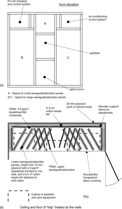
Figure 23.6 Rear wall absorber system. (a) Allocation of space. (b) Plan view
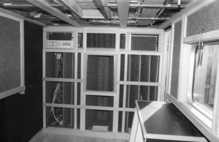
Figure 23.7 Exposed rear-wall trap (absorber) system, with the central jackfield mounting installed, and the cable access hole visible below
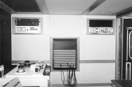
Figure 23.8 The completed rear-wall absorber system
The remainder of the space was then fitted with angled waveguide panels. The small volume, above the jackfield and between the control panels, was fitted with ten small, suspended rectangles of PKB2, at an angle of about 30° to the incident wave. The larger spaces, at either side, were each fitted with five panels of 10 mm plywood, slotted into wooden guide rails and supported on 10 cm of foam rubber. The panels were set at about 30° from the vehicle front/back centre line, and were mirror imaged. They were covered on one side by a layer of LA5, a deadsheet material of 5 kg/m2, to damp the panel resonances, after which each side was covered in A1. The whole rear absorber system thus consisted of panel absorbers, lined duct absorbers, waveguides to break the incident plane wave, and membrane absorbers. The large jackfield and its attendant masses of cabling further helped in the overall absorption and diffusion.
23.3.2 Frequency Breakdown
The operation of this type of wide-band absorption system can be explained as follows. Frequencies below 80 Hz, or thereabouts are largely lost by absorption within and transmission through the walls of the vehicle. Releasing 70 dB SPL (linear) at 50 Hz may not be acceptable within a building, but to the outside world it will generally be lost in background noise, and represents something in the region of only NR35, which is unlikely to cause disturbance. The SPL will also tend to reduce rapidly with distance from the vehicle, because, unless parked in a narrow street, the waves are free to expand in the outside air. Frequencies in the region of 50 to 200 Hz are absorbed to a large degree by the membrane absorbers, and by the wall structure of the vehicle. The 200 to 500 Hz region is addressed by the absorption within the system of ‘waveguide’ panels. These consist of cotton-felt-covered, damped, plywood panels of 130 cm by 50 cm. The lined ducts, which they form, generally soak up a very large proportion of the frequencies above 500 Hz.
The angling of the ducts, to form waveguides, also tends to increase the effectiveness of the membrane absorbers, by steering the incident wave and causing it to strike the membrane absorbers at angles that are more conducive to absorption, and by confounding the attempt of the weakened reflected waves to re-enter the listening area. Work by Walter,1 carried out at the Institute of Sound and Vibration Research, Southampton, UK, has demonstrated the degree of this waveguide effect. Figures 23.9 and 23.10 show examples of the waveguide effect of such systems. This data is previously unpublished.

Figure 23.9 Effect at single frequencies. Typical maps showing distribution of phase and amplitude at two different frequencies. Panels with one layer of felt, 45° angle and 30 cm spacing
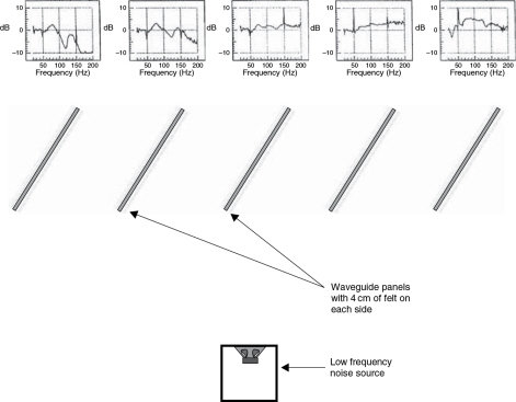
Figure 23.10 Pressure distribution behind the ‘trap’ waveguides – SPL versus frequency. The low frequency noise source was corrected for a flat frequency response. The five plots, above, show the deviation from a flat response at the corresponding locations on the other side of the waveguide panels. The steering effect of the panels can be seen, removing energy from the left hand side of the array, and adding energy to the right hand side
By this stage, we finally had an acoustically controlled shell, but we still had the problem of how best to drive it. What was needed was a high quality, small monitor system which could deliver around 110 dB SPL and which was suitable for very close range listening. The practical layout for the vehicle necessitated that the mixing console should be across the width of the truck, and should be as close as possible to the monitor wall. This resulted in each side wall being within one metre of the ears of the recording engineer, with a floor about one metre below, and a ceiling about one metre above. The distance from the listening position to a line drawn through the centre of the two loudspeakers was also about one metre. The brief for the design required a peak monitoring level capability of approximately 105 to 110 dB SPL and that the response should be sufficiently flat for serious mixing for CD releases.
23.3.3 Side Wall Reflexions
Placing the loudspeakers in the end of what is effectively a closed tube is not a particularly easy means of achieving a flat response. In fact, mobile recording vehicles through the ages have been plagued by the problems thus created. The first problem to arise is due to the proximity of the side walls. Given a 2m by 2 m front wall, there is little space to get an adequate stereo separation, so, inevitably, the loudspeakers must be sited more or less adjacent to the side walls. At high frequencies, where the wavelengths are less than about twice the distance from the centre of the loudspeaker to the wall, severe comb filtering can result from wall reflexions, as shown in Figure 5.12. In fact, and perhaps even more disturbingly, the side wall reflexions can produce severe smearing of the stereo image, not only because of the displaced phantom source of the reflexions (the mirrored room effect) but also because, with very close walls, the reflexions can return within the 0.7 ms time window before the Haas effect begins to apply. Such reflexions can be ruinous for the clarity of perception2,3 as the Haas effect/Precedence effect (of the first arriving signal dominating) does not apply.
The solution for the above problem is to position an absorber system alongside the loudspeaker. The absorber must be effective down to frequencies where wavelengths will be sufficiently long that the reflected wave will return to the listener substantially in phase, and will not cause interference except to boost the output. For a path length difference between the direct and reflected waves of around 30cm, this would mean very effective absorption down to 300 Hz, or thereabouts. In small spaces, this may not be easy to achieve, but geometry can help the situation to some degree, as shown in Figure 23.11. Here, the loudspeakers are built into an angled section of the front wall, such that the side wall absorbers could only return energy back to the listener which emanated from 50° or 60° off axis. The effectiveness of the absorber determines the strength of the reflected waves. However, in this instance, the engineer could be brought very close to the loudspeakers in order to take advantage, as far as possible, of the direct sound.
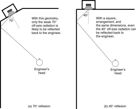
Figure 23.11 Effect of angling the loudspeakers. With most loudspeakers, the 70° off-axis radiation is likely to contain little above 300 Hz, and is also likely to be lower in high frequency content than in the case for the 40° off-axis radiation
23.4 Close-Range Monitoring
In the design of a vehicle like this, it is inevitable that the listening position should be close to the monitors. Large monitor systems cannot be readily used in such circumstances, because at short distances all multi-element loudspeakers exhibit geometrical problems, where the drivers covering different frequency ranges are perceived as separate sources, except, of course, for coaxial designs. In fact, coaxial designs initially appeared to be the optimum engineering solution for this problem, but the owners of the mobile studio in question expressed a lack of satisfaction with the sonic qualities of the coaxial loudspeakers commercially available in the size and power ranges required. The chosen solution was to use a pair of Quested Q405s, which had previously existed only in prototype form. These are shown in Figure 23.12, and in form are something of a hybrid between a d’Appolito array and a coaxial array. They were also small enough to avoid the above geometrical problems.
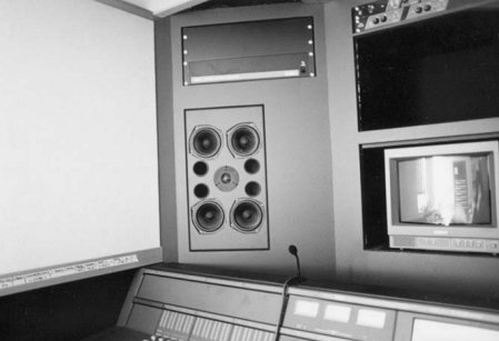
Figure 23.12 The Quested Q405
At the crossover frequency of 1.4 kHz, all five drivers operate, and the slightly elongated quincunx layout ensures a reasonably symmetrical horizontal and vertical directivity. Of course, at angles of 40° or 50° off axis, the one quarter wavelength differences due to the different distances to the nearest and furthest pair would begin to give rise to response irregularities, especially in the vertical plane where the driver pairs are spaced further apart, but in this case no such problem could occur. In this type of vehicle it is simply not possible to remain within any practical working area and be more than 20° or 25° off the axis of either of the loudspeakers. This fact is illustrated by Figure 23.13. Figure 23.14 shows the cancellation at the crossover frequency with the tweeter polarity intentionally reversed, with both loudspeakers (left and right) radiating, and measured at a central position within the working area. The cancellation, and hence the interference pattern, remains remarkably constant, with clean, steep sides. If any multiple-source smearing were present, such clean cancellation could not be achieved or maintained. Any potential problems in using so many drivers were thus confined to large off-axis angles that are of no relevance in such a vehicle.
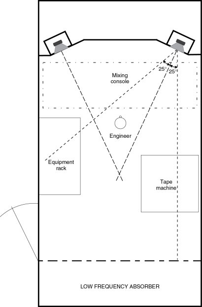
Figure 23.13 Loudspeaker coverage area. More or less the whole working area of the vehicle is within the 0–25° response field of the loudspeakers
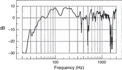
Figure 23.14 Cancellation notch at 1.6 kHz from out-of-phase tweeters. Both loudspeakers driven, measured at 2.5 m from back wall, on centre line of vehicle (10 drivers radiating)
23.5 Directivity and Total Power
Most loudspeakers designed for free-standing in conventional control rooms are designed to have a flat axial amplitude response when so mounted, but due to the omni-directional directivity of the low frequencies, below around 300 Hz the total power response tends to increase as the frequency lowers, and the directivity patterns broaden. If the low frequencies spread in all directions, whilst the high frequencies beam out in a narrower band, then clearly more total energy must be radiated at low frequencies in order to maintain an even SPL on axis. (See Section 11.4). However, due to room reflexions, the concept of a flat axial response from free-standing loudspeakers in a conventional room tends to be a contradiction in terms. In the case under discussion here, the loudspeakers were mounted in a rigid monitor wall, which due to the increase in radiation resistance provided by the constraint of the radiating angle, created a boost in the axial response below about 250Hz (see Chapter 11). This variability of mounting conditions is why the manufacturers of many active monitor systems provide low frequency level and roll-off controls, exactly to equalise this sort of response boost.
Conventional rooms also allow a degree of lateral and vertical expansion of the sound waves, but in a truck of the dimensions being discussed here, and given the incomplete absorption (including transmission) of the low frequencies by the walls, floor, and ceiling, the enclosure tends to act like a plane-wave tube. This has the effect of further increasing the low frequency radiation resistance, and boosting the output still further. The effect can clearly be seen from Figure 23.15. Nevertheless, this boost does provide a useful extension of headroom. Effectively, the increased resistive loading also increases the sensitivity of the loudspeakers, and because no non-minimum phase delays are involved in the response disturbance (such as is the case where reflexions combine with the direct signal after having travelled a significantly different path length) the problem lends itself to correction by relatively simple electrical equalisation. In these cases, the correction of the amplitude response will also tend to correct the phase response; consequently improving the time response. Corrective equalisation to lower the response elevation at low frequencies is further beneficial because it will increase the headroom by the same amount. This is an important factor to consider when trying to use the smallest practical source size to produce the required output capability of 110 dB SPL at one metre. Remember, large monitor systems were out of the question because of the geometrical and near-field problems. Inefficient, small loudspeakers may also suffer from thermal compression problems, therefore small and efficient loudspeakers are ideal. Although this is normally a contradiction at low frequencies, the special circumstances of the mobile vehicle make it achievable.
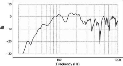
Figure 23.15 Axial response of one loudspeaker without sub-woofer or equalisation. Note the general boost in the 80–200 Hz frequency range, due to the restricted radiating angle
The above system, alone, was deemed to be lacking in bass for full-range monitoring purposes, so it was decided to employ a sub-woofer system to augment the lower frequencies, below 70 Hz. In general, the use of single sub-woofers on stereo systems for critical listening is not recommended, but again, in this case, the special circumstances not only demanded a single sub-woofer, but also allowed it to be used without the usual drawbacks. The sub-woofer was to be sited within a quarter of a wavelength of the main stereo pair at the crossover frequency. Indeed, if a pair of sub-woofers were to be used they would also, inevitably in this case, be located within a quarter wavelength of each other, and hence would tend to act as an acoustically coupled pair for mono signals. In this instance, the two would act as one anyway. The space saving benefit of using a single 15-inch woofer far outweighed any acoustic disadvantages, and offered the advantage of reducing the low frequency variability of panned images. The sub-woofer would also tend to drive the room like a plane wave tube, without significant reflexion.
As the room was rather absorbent, even at low frequencies, any modal activity would be very weak. Furthermore, in a space so small, the only mode that could develop in the sub-woofer range would be the first, axial, front-toback mode at around 57 Hz, below which a pressure zone would be in effect, giving a very smooth response. The use of the sub-woofer and its associated crossover would also prevent excessive low frequencies from entering the main stereo pair, thus easing their workload and increasing their reliability at high output levels. What is more, as the pressure zone exhibits an entirely minimum phase response, it can be electrically equalised, if required, without any detrimental effect. (See Section 13.5.)
23.6.1 The Appropriate Equalisation
In reality, it is impossible to predict the precise absorption characteristics of a mobile recording vehicle, or the exact loading effects created by the acoustic characteristics of the space. The problem is too complex, and too little is known of the inherent properties of the structure. However, because of the reasons previously described, it could be assumed that in the vehicle under discussion the response irregularities would be of a predominantly minimum phase nature, so an empirical method of evaluating the extent of the problems, and the required corrective measures, would be adequate.
After the installation, pink noise was put into the system, and a simple real-time spectrum analyser reading was taken. In highly damped rooms with low decay times and few reflexions, this is a viable technique. A high quality, multi-band, stereo parametric equaliser was then used to correct the response before listening tests were carried out. The equaliser was then adjusted until the optimum subjective response was agreed upon by a group of recording engineers, listening to ‘known’ material. Subsequently, the equaliser was re-adjusted to the nearest simple, smooth response correction, before the system was auditioned for a final check of its sonic acceptability.
The next step of the operation was to record the pink noise on to a DAT, from the output of the equaliser. The tape was then taken away for analysis, and the transfer function of the equaliser was plotted. The crossover used in this system had provision for the insertion of custom equalisation cards, and hence was a very practical choice for such circumstances. A card was subsequently inserted with the required characteristics to flatten the response. Its characteristics are shown in Figure 23.16(a).
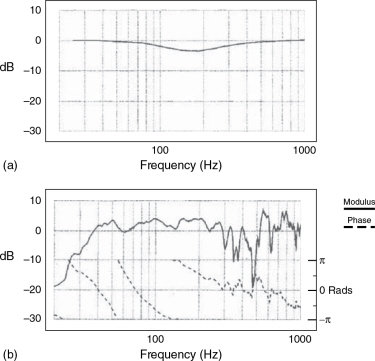
Figure 23.16 (a) Response of equaliser. (b) Equalised frequency response with sub-woofer
23.7 Results
The front end of the room is shown in Figure 23.17, with the sub-woofer just visible below the mixing console. The response of the final system in the recording vehicle is shown in Figure 23.18, which is a very commendable response indeed for a mobile control room. The ragged response in the 500 Hz region is due to reflexions from the top surface of the mixing desk, which are inevitable in such situations. The step function response is shown in Figure 23.19. It can be seen that the tweeter comes in about half a millisecond before the woofers, with the sub-woofer showing about a 3 ms arrival delay. In fact, the sub-woofer was a Quested VS115 situated under the console about half a metre ahead of the main monitors. The VS115 uses a 12dB/octave crossover at 38 Hz, which gradually augments and extends the falling response of the Q405s. Without the use of a sub-woofer, the ‘power response’ boost below 250 Hz, as shown in Figure 23.15, could be equalised down to flat, but the lower frequencies could not be boosted much, because the excursion limits of the 5 inch (125mm) drivers would have been exceeded below 60Hz if using monitoring levels of more than 85 dB SPL. In this particular instance, the sub-woofer was perhaps the only option available for an extended, flat, and an output capability of over 100 dB SPL.
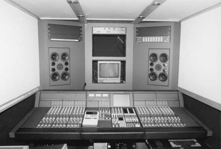
Figure 23.17 The complete front half of the truck, with the sub-woofer just visible below the mixing console
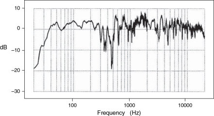
Figure 23.18 Frequency response of finished monitor system (the aberrations around 500 Hz are from the inevitable console reflexions)
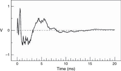
Figure 23.19 Step-function response
Of course, 12 dB/octave crossovers can never be correct in amplitude and phase at the same time. However, Quested had chosen to use them in the sub-woofers because of listening tests, and for this application, they are indeed very workable. The VS115 sub-woofer has a polarity reversal switch and a variable phase control. In this case, a reversed polarity and 90° phase shift produced the flattest amplitude response, but the phase inconsistencies can still lead to the errors in the time response. Such are the compromises with sub-woofers, which is why they tend not to be used in critical listening situations. However, here their use was a viable option in difficult conditions. The overall response in this vehicle is remarkably uniform considering the starting conditions. In fact, the ‘room’ performs better than many small, fixed rooms.
23.8 Conclusions
The Banzai mobile was clearly a great improvement on the first Manor Mobile in terms of its monitoring acoustics, though it must be said that the recording paths have not significantly advanced. Although the digital control system and general reliability have seen great development, the basic signal circuits, from microphone to tape, have not. In terms of the acoustics and monitoring, however, it is interesting to compare what could be done in 1998 with what could be done in 1973.
- Much more is now known about the psychoacoustics of monitoring, so more things can be taken into account during the design stages.
- The importance of the accuracy of the direct signal is much better understood, so more care can be taken to deliver it intact.
- Loudspeaker/room interactions are better appreciated, and the nonsense of using monitor equalisation to correct room reflexion problems has been largely laid to rest.
- The specialised acoustic deadsheets, which were extensively used in the Banzai mobile, were not available in the early 1970s.
- The rear-wall trap systems were in their infancy in the early 1970s, and had never been applied to mobile vehicles.
- In 1973, it would still be ten years or more to the birth of the ‘Non-Environment’ room concept.
- Small, high power loudspeakers were generally not available in 1973.
- There was no experience of the combination of acoustic control measures employed in the Banzai vehicle.
- ‘Slim-line’, high quality mixing consoles of the size of the Euphonix were not available.
There is no doubt that The Manor Mobile was the state of the art in 1973, but the electro-acoustic performance of the Banzai mobile, 25 years later, was clearly superior. From a designers point of view it is all very well looking back and thinking ‘if only . . .’ but the nine points above emphasise the developments that the intervening 25 years had produced. All in all, it was a very interesting exercise to undertake.
23.9 Summary
Sound propagation in a mobile recording vehicle of conventional dimensions tends to be more like propagation in a tube rather than in a room.
Where no space is available for adequate low frequency absorbers, the necessary absorption can be achieved through transmission to the outside of the vehicle if reduced sound isolation can be tolerated.
Console shape, size and siting can be crucial factors in the overall acoustic performance of a vehicle.
It is a good idea to try to reduce as much as possible the reflexions from the end wall opposite the loudspeakers.
Because of the very close proximity of the side walls to the loudspeakers, effective absorption should be placed on those walls in order to prevent the very early reflexions from smearing the stereo imaging.
Because of the difficulties encountered in achieving adequate acoustic control, close-range monitoring is a wise option, but the appropriate smallsize loudspeakers may lack an extended low frequency response.
Geometrical near-field problems can be ameliorated by the use of a concentric or semi-concentric driver layout.
Such a close-range monitoring situation fortunately lends itself well to low frequency augmentation by means of a sub-woofer.
References
1 Walter, Alistair, Private communication of internal ISVR document from which Figures 23.9 and 23.10 were extracted, with permission (1998)
2 Haas, H., ‘The Influence of a Single Echo on the Intelligibility of Speech’, Journal of the Audio Engineering Society, Vol. 20, p. 146 (1972)
3 Poldy, C. A., ‘Headphones’ in: Borwick, John (ed.), Loudspeaker and Headphone Handbook, 2nd Edn, p. 529, Focal Press, Oxford, UK (1994); 3rd Edn, p. 642 (2001)