The Monitor window has two sections: the Source view on the left, and the Program (or Sequence) view on the right.

The Monitor window.
I like to think of the Source view as a “prep” area. The typical workflow will find an editor taking a clip from the Project window into the Source Monitor to decide what section of the clip to use, then setting in and out points before editing it into the timeline.
The Program view is the playback of your timeline, or your edit. Many of us, who have been around since video editing involved only video decks, might refer to this monitor as the “record” monitor—like the monitor we used to view our completed edits played back on the record VTR.
A clip is brought into the Source view by dragging it out of the Project window into the Source Monitor, or by simply double-clicking a clip in the Project window or on the timeline. The Program view is actually the visual playback of the timeline and shows the frame that the current time indicator (CTI) is currently on, whether playing back or paused.
Although these two monitors have slightly different roles to play, there are some things that we can address right away which hold true for both.
The Transport controls at the bottom of each window control playback like a VCR. You can play, rewind, fast forward, and stop. The thumbwheel and slider can shuttle and jog (frame-by-frame) through a clip or sequence.
Both monitors have several options available from the wing menu.

There is a wing menu for both the Source Monitor and the Sequence Monitor.
Test Displays
If you are editing DV for personal use on videotape or for playback on a computer, chances are that your video doesn’t require a lot of adjustment if you choose not to do so. However, in the world of video and television engineering, the video signal must be tightly regulated. To monitor the technical aspects of the video signal, test displays, such as waveform monitors and vectorscopes, are utilized. Although the concepts of reading waveform monitors and vectorscopes could easily fill this book, there are some basics that users at almost every level can employ to make the test displays useful.
In the waveform monitor, you will notice a grid displayed that shows values from approximately –30 to +130. The negative values come from analog video engineering and are only there for two reasons: to make the test display familiar to professionals and to represent color saturation in darker areas of the picture. The part of the grid to focus on is the area between 0 and 100. You always want your video to be between these two numbers so that your digital video won’t clip. Clipping occurs when certain picture values exceed what can be shown. When you see values in your footage that exceed these boundaries, you may need to make some adjustments. Look for the lavender-colored line along the right edge of the display for the actual luminance range of your picture—very saturated colors can produce waveform over 100 due to the color (as opposed to the luminance) level or saturation, which may not make them “illegal.”
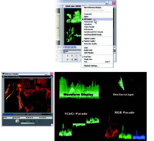
The test displays are available from the wing menu. An enlarged version of each of the four test signals is pictured, along with the actual video frame they are displaying.
The vectorscope has a different job from the waveform: its primary job is measuring color saturation and phase—you might think of it as “tint.” The distance from the center out is the amount of color saturation. The direction in which the waveform grows from the center indicates the phase, or just what color the color is.
An outer ring on the vectorscope display represents the limit of acceptable color saturation. If your video causes a vectorscope display outside the circle, you have a color that is too saturated for broadcast. You can identify which color is the problem by seeing where the color displays on the vectorscope display. There is a pie slice-shaped zone each for blue, cyan, green, yellow, red, and magenta: all the colors you would normally see in a test pattern display. Portions of your image that have no color saturation, such as white, gray, or black, show up as a dot in the center.
The YCbCr Parade and RGB Parade signals display the relative values of your image based on three color components of analog video. These are YCbCr (Y = Luminance, Cb = Chroma Blue component, Cr = Chroma Red component), also sometimes referred to as YUV, or the three base components of your computer display: red, green, blue (RGB). These displays can be used to do technical color correction or to track colors that are outside of acceptable limits.
If you want to learn more about how to understand these signals, refer to a publication such as Video Color Correction for Nonlinear Editors, by Stuart Blake Jones (Focal Press, 2003; ISBN: 0-240-80515-1) for details.
To access the test displays, do the following:
1 Move your cursor over the wing menu button located in the top right corner of the Program or Source Monitor.
2 Click the left mouse button to open the menu.
3 Drag the mouse onto the menu over the test monitor option you would like to select.
4 The selected test display will appear in the appropriate monitor. To return to video, simply reopen the menu and select Composite.
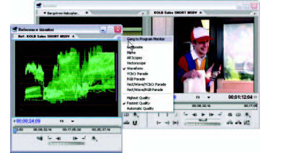
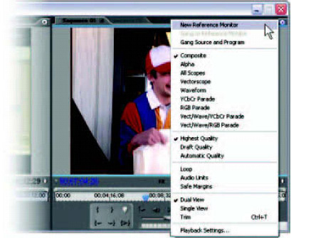
In the case of the Program Monitor, you can also create a new, floating monitor window for test display by selecting New Reference Monitor. The new window that opens will have the same options for video and test signal monitoring as the two monitors in the original Monitor window. The Reference Monitor can be nested in the Source side of the Monitor window, if you wish.
“Ganging” a Reference Monitor to the Program Monitor
You can link the new floating monitor to the program monitor so that both overlay windows update simultaneously. This may be useful when you would like to view the video picture in one window while viewing the video’s test display in another. The steps that follow describe how to link, or gang, the new reference monitor to the program output.
After you’ve created the new reference monitor
1 Click on the Wing menu button in the top right corner of the Reference Monitor window to open the wing menu.
2 Choose Gang to Program Monitor.
3 The monitor will now reference the same video as the Program Monitor.
4 You can also gang the Program Monitor to the new Reference Monitor through its wing menu, selecting Gang to Reference Monitor.
Once you’ve ganged a Reference Monitor, you will notice that updating each overlay window simultaneously will affect the real-time playback of your footage. To resume real-time playback and preview, close the Reference Monitor or select Gang to Program Monitor again, to deselect it.
Loop
The source clip or the program sequence can be set to loop the video between the in point and the out point, making it easier to scrutinize details than by constantly backing up and pressing Play. A clip or sequence can be set to loop through the wing menu or by clicking on the Loop button below the video picture in the Monitor window.
Audio Units
When you select Audio Units, the timeline switches from hours: minutes: seconds: frames to audio samples, making it easier and more precise to work with audio elements.
Depending on your system, you may want to adjust the quality of the video overlay on the desktop. The three settings are Highest Quality, Fastest Quality, and Automatic Quality. The Highest setting gives you the best-quality image but will tax slower systems. Fastest Quality lowers the overlay quality of your image (not the actual video) in areas where the software must render a preview, as in the case of transitions or applied video filters. Automatic Quality senses the capability of your system and adjusts accordingly. Each monitor (Source and Program) has its own quality setting in its wing menu.
Safe Areas
You can display a 10% and 20% safe window to show safe action and safe title windows over the video picture. These traditionally indicate safe composition for all television sets. The percentages can be changed in the Project Settings dialogue box. Safe areas can be applied through the wing menu or by clicking on the Safe Margins button below the video picture in the Monitor window.
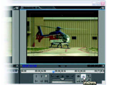
The Safe Margins button in the Monitor window.
You can make the Monitor window even smaller by choosing to display only one view. If you choose Single View from the wing menu in the Source view, only the Source view will stay open. The Program view will remain open if you’re selecting from the Program view wing menu.
Many times, an editor may decide to use an NTSC video monitor as a program monitor and cut down to only the Source view on the computer display. Other times, the Source view may not be necessary and you can free up space by closing it (for example, if you’re mixing audio).
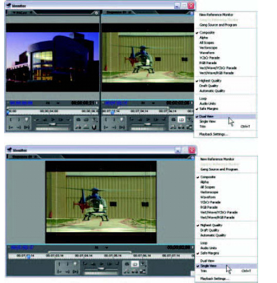
Dual View and Single View in the Monitor window.
Preparing a Clip in the Source Monitor
The source monitor is often used to preview and mark in and out points on clips before bringing them to the timeline. Here’s how to use the Source Monitor to prepare a clip:
1 Double-click on a clip in the Project window or drag a clip to the Source window.
2 Below the video window, you will notice a timeline with a blue cursor, or CTI.
3 Move the CTI until the video frame shows the point in the clip that you want to be the in point.
4 Below the left side of the timeline, you will notice two brackets. The open bracket ({) is to choose the in point. Click on it (or press the I key), and you will notice that the darker, blue-tinted stripe in the timeline shortens, to start at your newly selected in point.
5 By positioning the CTI at your desired out point and selecting the close bracket (}) (or pressing the O key), you’ve now marked in and out points on your clip.
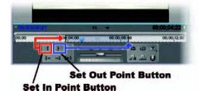
The Set In Point and Set Out Point buttons and a clip showing in and out points.
At this point, you can drag the prepared clip from your Source view to your timeline—but we’re going to cover that in much more detail in Chapter 6.

