5
BUSES, PORTS, AND INTERFACES
Storage and memory, when referring to computer data storage, are those components, devices, and the recording media that perform storage and memory functions and allow for the retention of digital data for a period or duration. Storage of the data, as one of the core functions of the modern computing system, may be thought of as “information retention.”
Memory is often referred to as a form of semiconductor-based storage. Semiconductor memory is usually fast, but may often only be utilized as temporary storage. This form of memory is known principally as random-access memory (RAM).
Mass storage is the nomenclature generally associated to more permanent forms of memory, such as optical discs, forms of magnetic storage like hard disk drives, and other types, which would be slower than RAM or flash memory. Mass storage also refers to huge amounts of data often stored in centralized libraries that are accessible by the masses.
History will reveal that memory and storage were originally defined by the terms “main memory” and “secondary storage,” respectively. Further discussion will find that those terms also make reference to “internal memory” and “external memory,” which in turn led to the evolution of network-based storage, that is, NAS and SANs. As comparatively large amounts of RAM are now found even in the simplest of netbooks, personal computers and workstations continue to grow; the lines dividing one form of storage from another have been blurred due in part to the advances and requirements for memory in all forms.
KEY CHAPTER POINTS
•Parallel and serial buses used for the functioning of storage and peripheral devices
•An exploration of the internal computer buses, such as PCI, EISA, and PCI-X
•Ports and storage bus standards comprising of SMD, ESDI, SSA, HIPPI, ATA and PATA, IDE, IPI, and SASI
•SCSI basics including command sets, identification schemes, arbitration, and bus bandwidth
Carrying and Transferring Data
In computer architectures, the subsystem that is the carrier or transfer medium between those components inside a computer or between computer subsystems is called a bus. The bus should not be confused with a network, especially when describing the transfer of data or information between computers per se.
The name came from electrical systems that called these buses (or busbars) after those physical highways that carried services such as power supply voltages, signaling services, and eventually instructional controls for external systems. Early computer systems utilized physical wiring bundles often arranged as parallel sets of insulated strands called ribbon cables (see Fig. 5.1), which interconnected memory components and peripherals together.
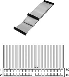
Figure 5.1 Layout of a 40-pin parallel ATA (PATA) ribbon cable that interconnects various parallel bus components, such as disk drives, inside the computer or server chassis.
Bus Types
In its most generic distinction, buses will generally carry data either in a parallel (bit per wire) mode or in a serial mode (single string on a differential or single-ended wire). In the early days of computer implementation, parallel interfaces were common at both the chip and peripheral connectivity levels. Over a period of time, as high speed requirements increased in frequency, interfaces migrated to serial architectures that are most prevalent today on devices such as USB, FireWire (IEEE 1394), the Serial Advanced Technology Attachment (SATA) interface, and other network-like interfaces.
Parallel Buses
Buses that carry data words in parallel, on multiple wires, are called parallel buses. Early disk drive interfaces were always parallel because serial technology had not been sufficiently developed, and a parallel bus could be easily implemented with the technologies, receivers, and transmitters of the early pre-1980s era.
Parallel SCSI, formally called the SCSI Parallel Interface (SPI), is an example for implementation of both the SCSI family and parallel interfaces or connections. The cable utilized to connect these devices was known as the Centronics 50-pin SCSI (see Fig. 5.2).
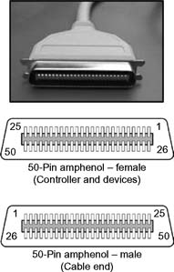
Figure 5.2 Centronics 50-pin SCSI connector.
Serial Buses
When the data is carried sequentially on a single wire, with a data rate that is much higher than a parallel bus, the signals are carried on a serial bus. A serial bus will inherently mitigate skew errors (i.e., the difference between signal timing) or cross talk (i.e., when signals appear in the adjacent wires of a parallel path).
Peripheral or Storage Buses
Distinctions between buses continue to evolve as storage, memory, and interface technologies advance. Storage buses have generally been segmented from other buses and are intended to address the connectivity protocols and formats for carrying information between host computer and storage-based systems. Storage buses originally came to fruition because the storage devices in the early days of mainframes and minicomputers were physically isolated due in part to their size. As data transfer demands increased, higher speed parallel buses improved and eventually migrated to serial formats.
As storage became more “detached” from the inner workings of the small frame workstation or PC, the portability of storage (and other related) devices for a computer evolved. The peripheral interface bus emerged with implementations such as Universal Serial Bus (USB), IEEE 1391 (as Apple’s FireWire or Sony’s i.LINK), Camera Link, EIA/RS422 and RS485, Apple Desktop Bus, MIDI, and even Fibre Channel.
Internal Computer Slot Interfaces
In addition to peripheral and storage buses, internal computer buses are used to carry data internally between slot-type cards and the central processing unit (CPU). Created in 1981 by IBM, the 8-bit Industry Standard Architecture (ISA) was the first motherboard slot type used on PCs. The ISA bus was updated to 16 bits in 1984 at the time when the PC AT was released. The 16-bit version operated at 8 MHz, with a maximum theoretical transfer rate of 8 Mbytes/second. This data transfer rate would be unacceptable for performance-demanding applications such as video and networking. This level of application required a migration to faster slot types, all with a target goal of increasing the performance of peripheral devices.
Selected examples of interconnect and computer buses include the following:
•Peripheral Component Interconnect (PCI) from Intel
•Peripheral Component Interconnect Extended (PCI-X), a highperformance motherboard slot type created by HP, IBM, and Compaq for use on servers, available in two speeds in PCI-X 1.0 and four speeds in PCI-X 2.0
•Extended Industry Standard Architecture (EISA) created by Compaq (now HP)
Storage Bus Standards
To better understand how storage technologies for moving media applications have evolved, the following sections will discuss some of the storage bus standards and their implementations. Not all these buses can be addressed in great detail; however, one can see that by virtue of the increased speeds and performance requirements in computer and media systems, the consistent evolution of storage buses marched forward while disk drive capacities and CPU speeds increased in lock step with Moore’s Law.
Moore’s Law
Intel cofounder, retired chairman, and CEO Gordon Moore predicted, in 1965, that the number of components the industry would be able to place on a computer chip would double every year. Moore updated his prediction in 1975 to once every two years. Nonetheless, what has become known as Moore’s Law remains a guiding principle for the semiconductor industry to deliver ever more powerful chips while further decreasing the cost of electronics.
Storage Module Device
The family of hard disk drive storage devices first shipped by Control Data Corporation (CDC) in December 1973 as the model CDC 9760 offered an unformatted 40-Mbytes capacity as a “ storage module device” (SMD) disk drive. Future variants of the CDC product line were announced in June 1974 through 1975 and included an 80-MB, a 150-MB, and a 300-MB version.
By definition, the SMD interface required two flat interface cables: an “A-cable” for carrying control commands and information, and a “B-cable” for carrying data. Each cable had to run from the physical disk drive to a controller and then to a host device (e.g., a computer). The interface’s transfer bandwidth was limited at 9.6 Mbits/second.
The SMD interface was supported mostly by 8-in. and 14-in. removable and nonremovable disk drives. SMD was mainly implemented on disk drives utilized in mainframes and minicomputers.
Future developments in the SCSI interface eventually replaced SMD around the mid-1980s.
The First 5.25-in. Hard Disk Drive
Called the ST-506, this 5.25-in. hard disk drive was introduced in 1980 by Seagate Technology (then called Shugart Technology). The ST-506 stored up to 5 Mbytes of formatted data. It was the drive used by IBM in its first generation PC/XT products. The drive was connected to a controller with three cables: a 34-pin common control cable, a 20-pin data channel cable, and a third that provided power for each device. A disk controller would be the interface between the drive and the computer.
A second generation drive, the ST-412, added a buffered seek capability and an onboard microcontroller that would move the head arm to the desired location without waiting for the mechanics to settle. The ST-506 had an average seek time of 170 ms with the ST-412 improving that by 50% to 85 ms. Seek times for the ST-412 would eventually get down to 15–30 ms by the late 1980s.
Enhanced Small Disk Interface
As a follow on to the first 5.25-in. hard drive (Shugart’s model ST-506), Maxtor Corporation developed an Enhanced Small Disk Interface (ESDI) in the early 1980s. ESDI improved on the ST-506 by moving certain parts that were traditionally kept on the controller (such as the data separator) into the drives themselves. The control bus was more generalized such that other devices, such as removable disks and tape drives, could also be connected. ESDI would use the same cabling as the ST-506.
ESDI could handle data rates of 10, 15, or 20 Mbits/second, whereas the top speed for the ST-506 was only around 7.5 Mbits/ second. ESDI would remain popular through the mid- to-late 1980s, with many high-end SCSI drives (of that era) that were actually high-end ESDI drives with SCSI bridges integrated on the drive.
By 1990, SCSI had matured enough to handle high data rates and multiple types of drives. ATA was quickly overtaking ST-506 in the desktop market. These events made ESDI less and less important over time, and by the mid-1990s, ESDI was no longer in common use.
Serial Storage Architecture
Designed as a peripheral interconnect interface (ca. early- 1990s) for all forms of storage or computer-related devices (e.g., CD-ROMs, tape drives, printers, workstations, servers, and storage subsystems), the Serial Storage Architecture (SSA) was pioneered by IBM’s storage subsystem development group along with other vendors/partners. When SSA development began, the stated goal was: “…to achieve high performance for a majority of applications and to provide a road map to growth in device data rates“.
SSA claimed high reliability with comprehensive error detection and recovery. It was implemented in low-cost CMOS requiring relatively little power. SSA did not require expensive and fragile cabling like SCSI interfaces.
SSA opened the door to a new storage interface standard (through the ANSI standard group X3T10.1). Intended as a replacement for parallel SCSI, one of the features of SSA was its ability to independently address different devices without being affected by other devices on the network link. To accomplish this, each SSA fundamental building block would be made up of a single port with a capacity to carry two 20 Mbytes/second conversations simultaneously (see Fig. 5.3).
By design, data protection for critical applications was guaranteed because a single cable failure would not prevent access to data. All the components in a typical SSA subsystem were connected via bidirectional cabling. Ring-based link architectures in the SSA network also had a built-in feature called “spatial reuse,” which permitted each link to operate independently.
As many as 192 hot-swappable disk drives could be supported per system with up to 32 separate RAID arrays supported per adapter. When SSA was deployed in a server/RAID environment, it was capable of providing up to 80 Mbytes/second of data throughput; with sustained data rates as high as 60 Mbytes/second in non- RAID mode and 35 Mbytes/second in RAID mode.
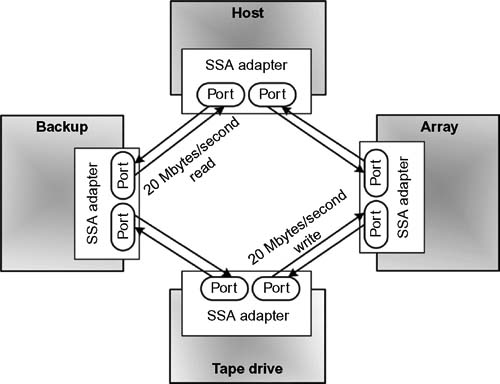
Figure 5.3 Serial Storage Architecture (SSA) connectivity with nodes and ports.
High-Performance Parallel Interface
HIPPI, a standardized point-to-point protocol popular in the late 1980s through the mid-to-late 1990s, is used in the attachment of high-speed/high-performance storage devices to supercomputers.
Initially (ca. 1987) the HIPPI implementation was defined for a 50-wire twisted pair cable, running at 800 Mbits/second (100 Mbytes/second) on a 32-bit data bus. HIPPI was later upgraded to a 1600 Mbits/second (200 Mbytes/second) with a 64-bit data bus running on optical fiber cable. In an effort to further improve the speed, the HIPPI-6400 standard, which was later renamed the Gigabyte System Network (GSN), offered a full-duplex bandwidth of 6400 Mbits/second (800 Mbytes/second) in each direction.
In November 1991, three years after the initial draft was delivered to ANSI, HIPPI became the first national standard for Gbits/ second data transmission.
HIPPI is no longer used considering that the widely available Ultra3 SCSI provided transfer rates of 160 Mbytes/second, and Fibre Channel continued its development offering a simpler interconnect for both HIPPI and SCSI with speeds of up to 400 Mbytes/second on optical fiber and 100 Mbytes/second on a single pair of twisted copper wires.
Many of the concepts and features developed for HIPPI are integrated into technologies such as InfiniBand.
IDE
The Integrated Drive Electronics (IDE) port is probably the most common and popular interface used by middle era (ca. 1990–2000) hard disk drives. During that period, IDE and ATA were the competitive lower cost alternative to SCSI drives (SCSI is discussed later in this chapter). Although the Advanced Technology Attachment (ATA) name is associated as a general purpose disk drive interface, the correct representation of IDE is actually ATA, which was reflected from the first IBM PC to use the original 16-bit Industry Standard Architecture (ISA) bus.
The IDE (or ATA) port is responsible for connecting IDE devices to the host computer. This port does not control the hard disk; therefore, it should not be represented as a controller.
The port/interface was popularized through the integration of the logic controller placed directly onto the hard disk drive chassis. With control of the IDE drivers resident to the disk drive itself, this implementation corrected many physically generated anomalies such as complexity, independence of the controller, and poor signal integrity.
Parallel ATA
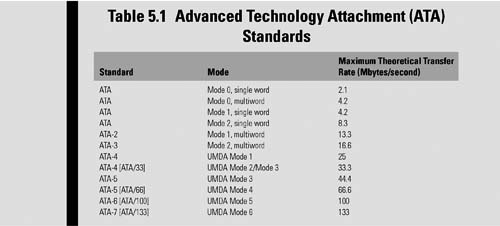
Developed as an interface standard for the connection of storage devices (e.g., hard disks, solid state drives, floppy drives, and CD-ROM drives) in computers, this standard is maintained by the X3/INCITS committee. PATA uses the underlying AT Attachment (ATA) and AT Attachment Packet Interface (ATAPI) standards.
Following the market introduction of Serial ATA (2003), the original ATA was retroactively renamed Parallel ATA (PATA). Parallel ATA is restricted to cable lengths of up to 18 in. (0.457 m), limiting the technology as an internal computer storage interface. By the beginning of 2007, PATA had largely been replaced by Serial ATA (SATA) in new computer systems.
The ATA and subsequent PATA standards evolved to include several transfer rates (see Table 5.1). Achieving these transfer rates requires special cables and that the port must support the transfer rate, the hard disk drive must support the respective transfer rate, and the operating system (OS) must be properly configured (e.g., bus mastering drivers and direct memory access [DMA] mode enabled).
SCSI
SCSI (pronounced “scuzzy”), more properly called the Small Computer Systems Interface, is the computer systems interface that is one of the most widely adopted and utilized storage buses in modern history. SCSI improved upon the IDE/ATA interfaces and has its root beginnings between 1979 and 1981 when Shugart, working with NCR, developed the Shugart Associates Systems Interface (SASI) as a scheme that would address devices logically rather than physically. The SCSI addressing scheme would be parallel in structure and byte-based.
IPI over SASI
To place disk drive development in perspective, recall that in 1975 the personal computer was only a hobbyist’s dream. Any incorporation of a floppy disk or a hard disk drive into the yet to be invented IBM PC was still several years away. By 1980, the IBM PC was still only a white board concept. The American National Standards Institute (ANSI), in 1980, had rejected standardization of the proposed Shugart Associates SASI standard and preferred Intelligent Peripheral Interface (IPI), a servercentric storage interface used in the 1980s and early 1990s (standardized as ISO-9318), which ANSI thought would be more sophisticated than SASI.
Arguments among developers included controversial topics such as using a differential versus a single-ended interface, a 10-byte versus 6-byte commands, and a serial versus parallel argument, which was technologically too far advanced for productive implementation.
As is typical in the realm of advancing technologies, product development continued whereas the standardization process stalled. By 1982, ANSI committee X3T9.2 was formed, and the basis of SCSI, as it would eventually be known, was developed. In 1984, the draft proposal was completed and submitted to ANSI for approval. Subsequently, by this time, device controllers and host adapters were already in the market. Apple Computer had introduced the Macintosh, which used the yet to be standardized SCSI principles for its storage and peripheral interconnects.
Common Command Sets
ANSI X3.131-1986 was finally published in its approved form as SCSI-1, but not without a rash of headaches that had surfaced as a result of nonstandard products already in service throughout the marketplace. Between 1984 and 1986, as more SCSI drives came in the market, it was discovered that a separate driver had to be written for nearly each type of drive. Finally, as a means to clarify and quantify the many variations that were being identified, the evolutionary development of a Common Command Set (CCS) for hard disk drives was begun.
The CCS was essentially a means within a protocol that described how host devices would access and communicate with other devices (e.g., drives, scanners, printers, etc.) The early CCS proposals were not mandatory, and each manufacturer figured they could interpret them as they needed.
SCSI Evolution
As with any emerging technology, SCSI developed from an 8-bit parallel architecture with 6 m cables through its UltraSCSI forms, and eventually moved from a parallel to a serial implementation. With these changes came not only increases in bandwidth but also changes in the physical and logical interfaces.
The remainder of this chapter will deal with the parallel implementations, and the following chapter will discuss the serial versions, including SATA, eSATA, and iSCSI.
SCSI-1
SCSI-1 employed an 8-bit parallel bus and utilized a parity scheme. SCSI-1 ran either asynchronously at 3.5 Mbytes/second or synchronously at 5 Mbytes/second. The maximum permitted bus cable length was 6 m, which was better than the 18-in. (0.45 m) limit of the ATA interface. The electrical interface used was low voltage; however, there were implementations that included a high-voltage differential (HVD) version with a maximum cable length of 25 m.
SCSI-2
Introduced in 1994, this standard provided the roadmap to what would become Fast SCSI and Wide SCSI.
Fast and Wide SCSI Variants
Fast SCSI doubled the maximum transfer rate to 10 Mbytes/ second, and Wide SCSI doubled the bus width to 16 bits. These increases allowed Wide SCSI to reach a maximum transfer rate of 20 Mbytes/second. These improvements suffered the penalty of reducing the maximum cable length to 3 m, so utilization was limited to very short connections between host computers and external disks.
SCSI-2 further specified a 32-bit version of Wide SCSI, employing two 16-bit cables per bus. This implementation was not widely accepted by SCSI device vendors due to its cost and the close-onthe- heels development of SCSI-3.
SCSI-3
The first parallel SCSI devices that exceeded the SCSI-2 Fast and Wide capabilities were simply designated SCSI-3. SCSI-3 was called the third generation of the SCSI parallel interface and was also known as SPI-3 for SCSI parallel interface number three.
Ultra and Fast-20 SCSI
Introduced in 1996, these variants doubled the bus speed to 20 Mbytes/second for the 8-bit (narrow) systems and 40 Mbytes/second for 16-bit (wide) systems. Although the 3 m maximum cable length remained, the single-ended Ultra SCSI development suffered from an undeserved reputation of unstable or extreme sensitivity to cable length and other fault conditions. The cheap manufacturing of the connectors and terminators triggered the blame for the failure, and ultimately the demise of this era of Ultra and Fast-20 SCSI development.
Ultra-2
Sometimes referred to as LVD SCSI, Ultra-2 SCSI was introduced around 1997, and its implementation featured a low-voltage differential (LVD) bus. LVD provided a much greater resistance to noise, which in turn allowed for a maximum bus cable length of 12 m.
Despite the data transfer rates, which increased to 80 Mbytes/ second, technology was now advancing much faster than widespread implementation, and the Ultra-2 SCSI lifespan was relatively short. It was not long before Ultra-2 SCSI was superseded by Ultra-3 (also known as Ultra-160) SCSI.
Ultra-3
Known also as Ultra-160 SCSI, this version was introduced around the end of 1999. Ultra-3 was a basic overall improvement on the Ultra-2 SCSI standard, whereby the transfer rate was again doubled to 160 Mbytes/second through the deployment of double transition clocking.
Ultra-160 SCSI further offered other new data related features including an error correction process called cyclic redundancy check (CRC) and domain validation (and negotiation), a feature that improves the robustness of the process by which different SCSI devices determine an optimal data transfer rate.
Ultra-320
Another working draft (Revision 10) came forth on May 6, 2002, doubling the transfer rate of Ultra-160 (to 320 Mbytes/second). By the end of 2003, nearly all SCSI hard drives being manufactured were of the Ultra-320 family.
Ultra-640
Known also as Fast-320, Ultra-640 was promulgated by INCITS as a standard (367-2003 or SPI-5) in early 2003. Doubling the interface speed from Ultra-320, to 640 Mbytes/second, the Ultra-640 standard pushed the limits of LVD signaling and further deteriorated the cable lengths making it nearly infeasible to chain more than one or two devices on the bus. By this time, most manufacturers left the parallel-SCSI architecture and looked forward to the development of Serial Attached SCSI (SAS) for their future.
SCSI Command Sets
The organization of data on the drive or associated peripherals is of little concern to the host computer as the interface presents the data to and from the host in a uniform or standardized method. Peripherals can manage their own housekeeping without bothering the computer host itself. Housekeeping functions such as control of media flaws, file allocation table structures, spindle and head/arm control, and others are performed as device-specific background tasks.
SCSI Identification Number
SCSI devices identify themselves using what is called a SCSI ID, a unique number that addresses each unique device on the bus. The SCSI bus can address up to eight logical units (LUNs). Typically, the numerical ordering for the LUNs is from 0 to 7, and each LUN can play the role of either a target or an initiator.
Initiator or Target
The device that originates the signal, pole, or inquiry is referred to as the initiator. The SCSI ID of the initiator is generally set to the highest priority value (e.g., “7” in an eight device implementation). Should there be two initiators, their SCSI IDs are usually set to 7 and 6. The remaining SCSI IDs would be used for disk drives or other target devices.
The target will be the device that the initiator intends to reach. This concept is extended throughout data peripheral interfacing technologies.
The “initiator” will generally issue a command or request, and the “target” will execute that request. SCSI, by design, must consist of at least one initiator and one target device. Some SCSI devices can act as both initiator and target.
The initiator is considered by most to be the host adapter and is generally awarded the highest number, 7, as its SCSI ID. The first device, usually the system drive, is then given 0, and for the most part, these are the only two IDs that need to be in the system.
Generally, SCSI ID 0 has the lowest priority, and 7 has the highest priority. Devices with SCSI ID 1 through 6 are typically ordered such that the next number, 1, is the second hard disk drive, followed by any removable media, scanners, printers, etc.
The computer may have more than one SCSI bus, usually referred to by letters (i.e., bus A or bus B). In this case, the buses must be “balanced,” that is each side must contain the same amount of SCSI devices on each bus. SCSI buses can effectively increase the number of devices on the bus. When 32-bit SCSI-3 was implemented, up to 32 devices would be supported.
A single SCSI ID can apply to an entire set of drives, such as in a single RAID array. By definition, the RAID array appears as a single drive, although it may consist of dozens of drives in a single enclosure or group of enclosures.
Arbitration
SCSI is both a logical and a physical scheme. At the high level, it contains a logical protocol used to communicate between computers and peripherals. At the low level, it defines the wiring scheme to connect a variety of physical peripherals.
All SCSI commands start with a process called “arbitration,” which is initiated because when one or more devices attempt to access the bus, something must decide (i.e., arbitrate) which signal gets which level of attention. During this arbitration phase, 8- or 16-bit data bus signals will be used to identify which device(s) is requesting access. To ensure proper arbitration, all SCSI devices on the bus must implement the same arbitration algorithm so that the resultant pole result is always unanimous.
Priorities
The priority sequence for an 8-bit-wide parallel SCSI bus is relatively simple; yet the priority sequence for a 16-bit-wide parallel SCSI bus must meet legacy requirements, which complicates the arbitration phase.
Bus Bandwidth Limitations
The arbitration process induces a considerable degree of overhead. During the time when arbitration occurs, no data is transferred on the bus, which can use up a lot of bus bandwidth. To this end, the SCSI-3 Parallel Interface (SPI-3) standard defined a feature that reduced the overhead experienced during arbitration. A simplified protocol, one of the five optional features of Ultra-3 SCSI, is called Quick Arbitration and Selection (QAS), which is also known as “quick arbitration and select” or by IBM’s name “arbitration select,” or by Adaptec’s name, “quick arbitrate.”
QAS reduces the number of times that arbitration must occur on the bus. When employed, a device waiting for the bus can access data more quickly after the device on the bus sends its completion signal and without having to initiate a new arbitration process. Although this could lead to domination of the bus, a provision in the specification mitigates the unfair blocking of other devices that may be of a lower priority, or may not implement the QAS processes.
Further Readings
Serial ATA International Organization (SATA-IO).
http://www.serialata.org/
Peripheral Component Interconnect Special Interest Group (PCI-SIG).
http://www.pcisig.com/
Serial Storage Architectures (SSA) — Chapter 36 (pp. 443–458)
“Video and Media Server Technologies,” Karl Paulsen (Focal Press)
“HIPPI—the first standard for high-performance networking,” Stephen C. Tenbrink and Donald E. Tolmie, Los Alamos Science, Number 22 (1994)
1394 Trade Association and Whitepapers.
http://www.1394ta.org/index.html
http://www.1394ta.org/press/WhitePapers/Firewire%20Reference%20Tutorial.pdf
Universal Serial Bus and USB Implementers Forum, Inc. (USB-IF).
http://www.usb.org/home