16
HIGH-PERFORMANCE ANDSHARED STORAGE
Scaling your storage system without having to engage a forklift upgrade is a challenge that will haunt IT administrators, managers, and the finance department of organizations throughout the life of any system. As the demands for capacity increase and throughput continues to grow, eventually one of many situations will negatively expose decisions that were made early in the deployment of the current “legacy” storage system in use today. Some of these situations are unavoidable, as they are a product of the normal and expected course of business activities and were financially impractical to address at the time. Other practices that can be employed today may reduce the impact of major changes that will naturally occur as technology advances.
This chapter looks at the causes and effects of these situations, in hopes of preparing the user for the growth they will have to address in the future. The topics that follow should help to expose the various solutions and guide the users to a properly crafted storage solution for today and tomorrow.
In the concluding portion of this chapter, a deeper look into shared storage is taken where many of the elements previously discussed in the chapter will be applied to considerations for core shared storage platforms that must be designed to live in the real world of progressively adding storage (and client workstations) to a legacy environment.
KEY CHAPTER POINTS
•How to employ the concepts of a SAN storage accelerator appliance to improve overall performance in a file-sharing environment
•Issues in production and postproduction workflows that develop when certain forms of storage (DAS, NAS, or SAN) architectures are utilized to solve short-term issues, but with long-term impacts
•What intelligent, adaptive storage means and how is it applied to systems that must handle large file sizes in real time and in concurrent collaborative work environments such as those in postproduction
•How extreme performance, scalability, and advanced data management can aid in supporting SAN, NAS, and combinations of the two
•Storage consolidation for smaller SANs, and issues of contention, cache coherency, latency, and load balancing; plus the impacts on I/O block size requests and file-sharing SANs
•Scaling of NAS systems, including topics regarding limitations, management, and latency
•Scale-up and scale-out systems, what they are, and their advantages and disadvantages
•Considerations for constructing, upgrading, and using a shared storage environment; and how resiliency, performance, connectivity, and expansion are so interrelated
Applications for High-Performance Storage
High performance intelligent storage platforms continue their advancement as they are deployed within media organizations and service providers at an astounding rate. Such storage systems are now far more prevalent in companies that develop and produce content, that distribute content to users, and that provide the production platforms for the gaming, motion picture production, postproduction, and broadcast entertainment businesses. These storage platforms are now integral components in the workflow. They provide the scalability, performance, density, and power efficiency necessary to store and manage the enormous amounts of unstructured data that power the digital entertainment world.
The entertainment industry has moved deep into the entire digital world. Although today’s content is created and stored digitally, there has become a growing fundamental migration in how that content is not only produced but also distributed; one that leverages high-bandwidth distribution via the Internet at a level of consumer quality equal to or better than broadcast high-definition television and video. This migration is taking place across the entire industry from broadcast television stations to film studios, to production houses, and to digital intermediate (DI) facilities.
The industries have all witnessed an extremely rapid growth in very large media files. These digital images, video, and audio account for 85% of total storage capacity; material that consists of unstructured data as opposed to the transaction-based data that dominated many organizations in recent times.
Traditional storage architectures that were optimized for transactional data are not well suited for this evolving digital world. Storage systems must now employ technologies capable of handling very large files in real time. The platforms must be able to expedite workflows, while providing the paths to stay ahead of this exponential capacity growth that requires supporting millions of users, storing billions of images, videos, and music files, and delivering these files to other systems with submillisecond response times. All the while, these systems must continually provide the ability to stream massive amounts of high-definition content without ever missing a single frame. Storage platforms must be capable of delivering write performance that equals system read performance. The systems must be able to provide a guaranteed quality of service with predictable performance on large files while simultaneously ingesting multiple sets of data streams.
Postproduction
Motion picture and digital media content creation are made possible by the collaboration of teams that comprise a massive mix of production activities. Those activities include the creation of visual effects, 2D and 3D animation, main titles, and trailers, and mixing sound. The releases consist of feature films, television, advertising, interactive visual media, and video games. Today’s postproduction houses and boutiques feature many subsets of the same digital capabilities; some offering end-to-end solutions and others only providing a specific, usually specialized activity.
In order to meet the often stringent deadlines, real-time collaborative workflow is required. Collaboration is essential to a successful postproduction process, no matter if the company offers the full end-to-end solution or is simply a segment of the overall production process. These operations cannot tolerate system downtime, inaccessible data, or reduced throughput because of data transfer bottlenecks.
Today’s workflows must now create content of increasing complexity for a distributed environment and at a mix of resolutions ranging from HD (1K) to 2K, 4K, and 8K (UHDTV) formats. Most organizations are finding that they are technically challenged when it comes to supporting a mixture of real- time workflows, including concurrent multiuser editing and colorists and growing file sizes that begin at ingestion station and then continue to expand throughout the postproduction process or through multiple releases of the content that must be packaged per the contractual requirements from the marketing side of the organization. Conventional storage systems are often found to be inadequate for this level of postproduction, so they turn to highly intelligent, high-performance storage solution platforms and subsystems for their answers.
In a working postproduction environment, a central storage system may be called upon to support edit-in-place functionality for dozens of Apple Final Cut Pro uncompressed HD workstations while at the same time streaming four sets of uncompressed 4K content streams for the editing processes of a feature film. Such extreme performance might require as much as 240 GBytes/second of scalable storage capacity, which then must support open systems consisting of multiple CPUs, operating systems, and file systems; all in a collaborative file-sharing environment.
Broadcast
Broadcast entities now find themselves developing content, preparing content in multiple formats, and then distributing multiple streams in support of consumer demands for on air services, online streaming for mobile phones and media players, and delivery to Web portals for distribution over the Internet. In an environment that thrives on competition comprised of a mixture of hundreds of cable channels, satellite broadcast, plus YouTube, Netflix, and video-on-demand, the activities supporting content production and delivery are growing at an alarming rate.
These expanding activities require another breed of high throughput and scalable storage systems that not only are able to support real-time collaborative workflows but also must be able to store the billions of files that make up the unstructured data found in static images, videos, and music.
This caliber of storage system must be designed to specifically handle extremely large files at very high throughput. On a daily basis, the volume of new content can easily exceed multiple terabytes, which can only be enabled through concurrent digitization on multiple ingest stations.
All the while, this same storage platform must be capable of concurrently delivering multiple gigabytes of data to editing stations, playout servers, transcode farms, render farms, and content distribution networks. Video playout depends upon the flawless streaming of video, so the storage platforms must deliver real-time performance with uncompromising reliability.
Graphics and effects have historically operated in a parallel job task fashion, but usually on silos of individual stores that are either locally attached to the workstation or contained in small NAS (occasionally SAN) systems optimized for the types of workflow suited to their needs. In contrast, news editing environments have traditionally found their staff doing most of their operational duties sequentially, rather than in parallel. Intelligent storage systems offer parallel storage solutions that are changing the news and graphics/effects models by enabling a centralized repository of managed files with performance equaling and usually exceeding earlier archaic solutions.
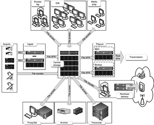
Figure 16.1 A typical large-scale broadcast production and transmission environment.
Video Gaming
Game makers continually must address the challenges of producing highly successful upcoming products in shorter release cycles. The games must now be tailored with heightened sophistication and expectations are higher for both physical media releases and the growing number of online multiplayer gamers. Although gaming on physical media continues to enjoy growth, the new contender has become distribution platforms that rely on the Internet for both content and live gaming, both of which are providing new revenue streams for video game companies.
New intelligence must now be built into storage systems so as to handle the large multimedia files and high-performance requirements found in collaborative workflows that are a critical part of the game developers’ production processes. Games must now be capable of reacting to users at submillisecond response times; employing multiple streams in a single session; and dealing with millions of users that are accessing multiplayer games over the Internet at unpredictable time intervals.
This expanding reach requires that current storage platforms be able to power two kinds of environments—the production development environment and the provisioning of live interactive services for real-time gaming. These necessitate that multiple applications must now run simultaneously in parallel, while still providing tremendous performance and capacity. Storage density increases now find that users are managing 2 or 3 Pbytes of storage capacity in only a couple of floor tiles of data center real estate all the while delivering sustained throughput at upwards of six or more gigabytes per second for both writes and reads. And all this must be deployed repeatedly for every new title that is produced.
Roots of Intelligence
Intelligent storage solutions first became evident in the early part of 2000; however, as is typical to all technologies, such solutions have since expanded in lock step with industry needs, storage densities, and performance requirements. Once video compression, high-resolution and high-definition images, and techniques for larger format and digital cinema production began, it became more apparent that size did matter and the industry would need to address the scaling requirements for storage in earnest.
The remainder of this chapter explores solutions that support the interests and changes experienced in collaborative workflows and those environments that depend upon an all-digital production and distribution model.
Size Matters
The media and entertainment industry has gone through significant and rapid changes in recent times. With higher resolution content (HD, 2K, and 4K), file sizes are growing to incredible proportions requiring the implementation of intelligent systems that can manage high-performance storage with highly scalable capacities. As desirable as high-performance SAN storage and infrastructures are for real-time data capture, they can be equally undesirable for postproduction work. In general, SANs can be far too expensive and much too difficult to scale for workload sharing.
NAS has been a formidable answer for postproduction, with its built-in collaboration and workload sharing. The storage cost advantage of NAS over SAN makes NAS more attractive, and simpler to implement, operate, manage, and use. Regrettably, many NAS systems have not coped with the rapidly changing realities of the 21st-century media and entertainment (M&E) market space. As a consequence, we find that many users wrongly deploy their multiple sets of NAS, generating what is referred to as “NAS sprawl.” Once users adopt NAS for their solution, they find it proliferates more rapidly than expected, creating management, operational, and real estate headaches such as excess power consumption and cooling problems of huge proportions.
Intelligent Adaptive Storage
Storage systems need to be engineered so they can adapt easily and adjust on the fly to the ever-increasing performance and scalability requirements of media production and postproduction workflows. An adaptive environment with the means to scale only as required eliminates the problems of system proliferation. For the artistic and creative world made up of animators or special effect designers, one should look to intelligent adaptive storage platforms that can address the needs of their workflow and in turn eliminate both the short-term and long-term storage crisis.
In many segments of this industry, collaboration is an important requirement for the successful use of what is now a global workforce. Collaboration has never been more important for the world of digital postproduction editing, compositing, animation, special effects, color grading, mastering, and archiving. With this need expanding, we find that native SAN storage is less effective at providing collaborative workload sharing.
SAN and NAS Workload Sharing
To run workload sharing on a small, high-performance SAN environment, there needs to be a shared SAN file system. The problem is that when shared SAN file systems are scaled vertically or horizontally, system performance usually degenerates quickly. Production processes are routinely required to quickly push real-time content from SAN storage onto lowercost mid-level performance NAS for their postproduction work. Although a NAS implementation may greatly reduce collaborative storage costs, most NAS systems are unable to meet the demands of larger scale postproduction activities. As a result, users find they cannot effectively scale performance or capacity and thus experience serious performance and operational bottlenecks.
The end result becomes a postproduction storage crisis. However, in recent times, there have been many supplemental additions that support scaled-up, scaled-out, and collaborative low-latency high-performance solutions to aid in mitigating the storage crisis.
Storage Accelerators
Users working in an all-digital production environment depend upon several media-savvy systems that are capable of simultaneously managing the intake of rich media, providing for the various craft editorial and graphics applications, and distributing the media throughout the enterprise and to other users in a variety of formats and resolutions.The end result becomes a postproduction storage crisis. However, in recent times, there have been many supplemental additions that support scaled-up, scaled-out, and collaborative low-latency high-performance solutions to aid in mitigating the storage crisis.
To support these various activities, many users are moving toward a single, centralized storage network that is capable of providing significant productivity gains while at the same time dramatically lowering storage acquisition and operating costs. Any networked storage solution needs to meet the demanding quality of service (QoS) requirements of an often complex digital media production and delivery environment. Such environments require that their storage system delivers data at high speeds to often hundreds of servers and workstations simultaneously, reliably, and without content degradation.
Of the needed solutions that support this environment, one of them is concurrent access to consolidated content with a QoS level that remains sufficient enough to meet the demands of digital broadcast workflow, often both in realtime and faster than real time. Given that broadcast and content professionals are usually required to ingest, create, and deliver content simultaneously and in parallel, performance is extremely important to the storage and server system. When maintained at a high level, workflow efficiencies are improved, increased productivity is realized, and the total cost of ownership (TCO) is lowered.
Storage Appliance Technologies
To accelerate application performance, simplify information management, and to establish an intelligent platform for deploying application-specific storage software, appliance technology (introduced in the 2000–2001 time frame) is used as a far more advanced approach to data access than NAS or nonappliance SAN solutions. By coupling storage appliance technologies with file-based storage intelligence, the combined architecture increases manageability, performance, and reduces I/O bottlenecks more than was possible when using conventional “preappliance” Fibre Channel SAN technologies.
An appliance is a device or system that manages and accelerates the delivery of data to or from storage subsystems and hosts. Prior to these appliance-like technologies, so called “first generation” storage area networks (SANs) were found to impose several limitations and restrictions to systems that were trying to move data. One of the options employed by users was to create multiple SANs and then overlay a software layer that would transfer data from one SAN to another SAN. Besides being a costly measure, it was realized that this approach did not scale well and was profoundly difficult to manage.
An alternative option for first generation SANs was to stripe the content across several RAID controllers. However, this practice introduced latencies and contention (collisions) within the overall storage architecture that reduced the QoS desired. Furthermore, this practice still did not mitigate the system constraints in scalability, configuration, and management found in either option.
Fault Tolerance
Activities that occur during video postproduction may be called “video transactions.” These activities support the processes surrounding editing, color grading, animation wire-frame creation, and rendering and effects compositing. In the digital domain, most of these activities happen at high definition (1K) and above resolutions (e.g., 2K and 4K) and will routinely employ data rates that are in the hundreds of megabytes per second. Whether working at lower bit rates (using compressed 20–50 Mbits/second data rates), or with these very large files, there will always be a continual stream of video transactions and consequently, there remains a very high requirement to provide for fault tolerance while at the same time maintaining high availability. Along with the total bandwidth requirements for a storage system comes the demand for handling multiple sets of parallel transactions; something most conventional SAN architectures were unable to achieve using the technologies available during the early times of high capacity and high bandwidth storage system development.
SAN adaptations can deliver less performance and reliability and are often plagued by the complications associated with expanding or growing the SAN at an economical price tag. Delivering a guaranteed bandwidth to the production environment is essential when editing is to be carried out directly on shared storage. This model does not allow for file transfers to local storage, and thus, some SAN implementations must be further supplemented in order to help ensure maximum accuracy, efficiency, and consistency for all the hosts that attach to the store.
Figure 16.2 shows a conventional approach to a storage network with redundant servers cross feeding multiple RAID controllers. To address the complications of media-centric operations, devices including grid storage, large SAN architectures, and massively parallel compute systems have been modified to support the jumbo files associated with moving media storage technologies. New storage networking appliance technologies are available that have overcome many of the limitations in those first generation SANs, leading to the development of advanced acceleration components that aggregate the many legacy components of the conventional approach (see Fig. 16.3).
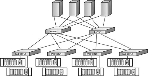
Figure 16.3 Typical high-performance network.
File-Sharing SANs
File-sharing SANs present special challenges for high-performance environments, among which are the performance and scalability issues that are common to rich- media environments. Extremely high performance and tremendous scalability in both connectivity and capacity present complex configuration issues for SANs.
SAN file systems that are often found in fairly large-scale deployments include systems with 40 hosts or greater or bandwidths in the hundreds of megabytes per second region. Significant challenges exist in scaling to that level particularly when each host demands such high levels of throughput; for example, when the systems reach a high-proportionate fraction of a full Fibre Channel connection.
Typical challenges include contention and switching latencies, which are exacerbated by the creation of high-speed volumes through striping by the host computers. Figure 16.4(A) illustrates a SAN configuration using eight typical RAID systems (or alternatively four dualcontroller RAIDs) plus a Fibre Channel switch. Figure 16.4(B) shows a similar configuration, but with a storage appliance comprised of equivalent single (or multiple) RAID-controller functionality coupled with silicon (solid state)-based caches in a dual protection mode.

Figure 16.3 Complex highperformance network using a common accelerator appliance in place of discrete storage controller nodes.
Several issues are immediately apparent in the configuration of Figure 16.4(A). First, note that each disk array has a dedicated RAID controller. In this mode, operationally, every storage access by any host might result in eight distinct transactions, one to every RAID system (or in pairs when configured in dual sets of RAID arrays). What this means is that there will be eight (or alternatively four) switching latency occurrences that could potentially reduce performance.

Figure 16.4 SAN configurations with discrete Fibre Channel controllers to R AID (A), compared with file sharing with an appliance-based SAN configuration (B).
Of greater impact is the effect of multiple hosts making I/O requests concurrently. Not only are there switching latencies to contend with, but far worse are the number of collisions present when trying to access switch ports attached to the individual RAID systems. Referred to as “contention,” this issue can severely limit the aggregate throughput provided through the Fiber Channel switch.
The combination of switching latencies and contention can degrade the actual aggregate throughput in a high-bandwidth environment by up to one-half of what the RAID systems might theoretically provide. The effects of switching latency and contention continue to worsen as both the number of hosts and the complexity of the switching fabric increase.
Consolidation U sing Smaller Storage SANs
Production facilities often will employ RAID sets or small SANs that are attached to a group of edit workstations (e.g., Final Cut Pro HD). A media director is used to allocate system, bandwidth and the interfaces to or from the file system, which sits over the top of the storage platform. As growth is experienced, the enterprise finds that the storage system has reached its limitations in capacity or performance, driving it to find alternative storage profiles or to consolidate the existing islands into something that is more productive for the whole of the organization. Eventually this scenario exhausts its options and the enterprise determines that the consolidation process is unproductive. These circumstances become elevated to the point that some other means to resolve the storage dilemma is necessary.
In those applications where it is desirable to apply consolidation methods to group sets of smaller storage sets, the performance or capacity of multiple RAID systems becomes impractical or insufficient. However, when higher performance is needed, and/or greater capacity storage is necessary, multiple RAID systems may still be required. This form of application is a potential candidate for virtualization through the deployment of a storage appliance. The advantages found in virtualization are such that it allows the disk pool resources to be allocated to any host, at the highest levels of performance.
This is more difficult with SANs where disks and associated data are captured behind individual RAIDs (see Fig. 16.5A and Fig. 16.5B).
In a small SAN it is possible that simple Fibre Channel switches may provide sufficient parallelism to ensure good performance to each host. This is the case where individual hosts “own” all of the storage behind a particular RAID controller. However, if multiple hosts access the storage behind a shared RAID controller, contention of the switch port to that controller will occur, which then degrades performance. This degradation is particularly punitive when moving large files that tend to monopolize port access and demand greater throughput from the RAID engine.
For instances where the user has employed smaller SANs, but still desires consolidation, there are further issues that must be considered. Some storage consolidation SANs may not achieve the performance benefits or capacity increases available from multiple RAID-based systems. However, one can use a storage acceleration appliance that is capable of providing more raw performance and scalability than many of the more capable dualcontroller RAID systems.

Figure 16.5 SAN consolidation using traditional discrete components (A); and consolidation using a dual, protected SAN storage appliance (B).
The point here is that users planning expansion through consolidation need to understand the impacts of moving from an overtaxed small SAN to the next level of storage. They should be certain that they would not paint themselves into the same corner they had by employing multiple smaller SAN islands.
Contention and Latency
The storage acceleration appliance can greatly reduce or potentially eliminate the contention and latency problems associated with a switch fabric. Host ports in the accelerator each provide collective parallel access to all storage resources without having to incur the punitive consequences of contention or switching latency. The concept is analogous to having multiple pipes leaving a reservoir of water; there is no need to wait for any pipe to provide water, and none of the pipes will interfere with each other—the result is that the downstream user can take as much as they need from any single pipe regardless of what is happening to the pipes next to or surrounding it. This is especially important when all the edit seats attached to the storage pool want access to many sets of files simultaneously.
Parallel host port capabilities in accelerators are a major differentiating factor for this kind of architecture when compared against straight traditional switching fabrics or other storage configurations. Parallel access not only improves fault tolerance, also provides for additional resiliency and bandwidth while simultaneously reducing latency.
Implications of Striping on I/O Block Request Sizes
Another limitation caused by striping that can limit performance in a file-sharing SAN is the reduction in I/O block size requested by each storage unit. When the host application makes an I/O request to a volume, it makes a request of a particular I/O block size. Block sizes typically will range from several hundred bytes (e.g., 512 Kbytes in a standard TAR) up through several megabytes or more when high bandwidth applications are employed.
Large block size requests are generated by applications that transfer huge amounts of data typical to video or imaging, or for applications in data mining or computational supercomputing. Disk storage systems, in order to achieve high throughput for rich-media applications, prefer to receive as large an I/O block size request as possible. For these applications, storage systems will attempt to maximize their throughput by requesting block sizes in excess of 512 Kbytes or more. The shortcoming is that most applications (and file systems) will limit the I/O block request size to a storage volume to the 1 Mbytes range; although in large super computers where there is a tremendous amount of real memory, or where block sizes may range well above these figures, the requirements scale differently.
Even for an example with an 8-way stripe, if the storage volume received a 512 Kbytes I/O block size request, it would still result in each individual storage unit only seeing 512 Kbytes divided by the 8-way stripe, or in essence only a 64 Kbytes I/O block size request. Such a 64 Kbytes block size would not come close to maximizing a storage unit’s throughput.
The storage accelerator appliance (with a solid state cache) provides simultaneous full-bandwidth access from each host port to individual data or to the same data in a shared disk pool configuration. Such an implementation enables very high-performance volumes to multiple hosts without the impediments of host-based striping (see Fig. 16.6).

Figure 16.6 Single-LUN virtualization in cache coherency ON mode.
To obtain full-bandwidth access from a single shared storage pool requires that the shared LUN be of very high speed. By RAID characteristics that allow a single LUN to be spread across an arbitrary number of parity group “tiers,” a single LUN can be constructed that can sustain in the range of 650–700 MBytes/second, provided that 512 Kbytes or greater I/O block size requests are possible.
A high-speed LUN of this type is created without the necessity of striping at the host or the SAN file system level. This results in three benefits being created: first is that large I/O block size requests may be realized at the storage unit; second is that the contention and switching latency “chatter” present in a switched fabric are reduced (should one be employed); and third, there is a reduction in CPU utilization that striping through the host computer burns up.
Media Directors
One of the components of storage accelerator appliances may be the “media director.” These units, which function like a server might, manage the activities between the hosts and the caches that are placed ahead of the storage disk arrays themselves. For protection, redundancy, and for enabling a smooth failover in the case of link losses, host bus adapter (HBA) failures, or even physical cabling issues, there will usually be two fully redundant media directors to act as the traffic cops for the flow of data between hosts and drives.
Media directors have multiple host ports and will include their own local cache often in RAM or as a solid state drive (SSD). Each of the host ports provide access to any LUN “owned” by that media director. Access to LUNs owned by the other media director may not be accessed unless cache coherency is enabled; this allows all ports from both media directors to access all the storage resources simultaneously.
Cache Coherency
Cache coherence is a special case of memory coherence. Also known as cache coherency, this functionality refers to the maintenance of the consistency of data that is stored in local caches of a shared resource.
In a system where clients maintain caches of a common memory resource, problems may arise with data that is inconsistent. This can occur in CPUs of a multiprocessing system or in memory storage systems with parallel ports from hosts acting to improve bandwidth or throughput. Figure 16.7 shows that if Client 1 has a copy of a memory block from a previous read, and Client 2 changes that memory block, then Client 1 could be left with an invalid cache of memory without any notification of the change. Cache coherence manages such conflicts and maintains consistency between cache and memory.
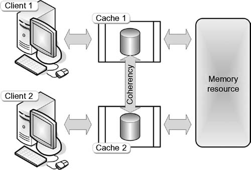
Figure 16.7 Cache coherency in a shared memory resource application.
The behavior of reads and writes to the same memory location is called “coherence.” Cache coherence (related to program order preservation) is obtained when the following conditions are met:
•When a READ made by Processor-P to Location-X follows a WRITE by the same Processor-P to Location-X, with no WRITES to Location-X by another processor occurring between the WRITE and the READ instructions made by Processor-P, then, Location-X must always return the value written by Processor-P.
•A READ made by Processor-P1 to Location-X that follows a WRITE by another Processor-P2 to Location-X must return the written value made by Processor-P2 if no other WRITES to Location-X made by any processor occur between the two accesses. This is a condition that defines the concept of a “coherent view of memory.” If the processors can READ the same old value after the WRITE is made by Processor-P2, then that memory is considered “incoherent.”
•WRITES to the same location must be sequenced. That is, if Location-X received two different values A and B (in that order) from any two processors, the processors can never read Location-X as B and then read it again as A. To paraphrase this, Location-X must be seen with values A and B and only in that order.
These conditions are defined with the supposition of instantaneous READ and WRITE operations happening precisely simultaneous with each other, an occurrence that is not possible given memory latency or other aspects of any compute or storage architecture. A WRITE by Processor-P1 may not be seen by a READ from Processor-P2 if the READ is made within a tiny period following when the WRITE was made. Such a memory consistency model defines when the written value must be seen by the following READ instruction ordered by the other processor(s).
Accessing Fresh Data
With cache coherency enabled, the hosts always access “fresh” data with no risk to file or file system integrity. Enabling cache coherency will have performance impacts whenever WRITE operations occur. This is because a WRITE’s data will be present only in the media director whose cache is attached to the host that performed the operation. When cache coherency is enabled, the system makes sure that a subsequent request for that data through a host attached to the other media director supplies only fresh data.
Such a validation process requires a period of time to perform; thus, a high-WRITE environment will degrade overall performance, whereas a high-READ environment will have little to no degradation since most data in this case is static. When dealing with load-balanced server forms such as with Web servers, media servers, ingest or download servers—or in other environments where there is a high ratio of READs to WRITEs—this is ideal.
Should a system desire a high-READ-WRITE performance, then cache coherency should be disabled. In such a high-WRITE environment, a configuration would be made that allows the host computers to attach to both media directors when required. Through the use of dual-pathing and through a switched fabric with one or more switches for redundancy (as shown in Fig. 16.8), or alternatively by using two Fibre-Channel Host-Bus Adapters in each host, which then dual-attaches each host to a separate media director/storage-appliance (as seen in Fig. 16.9).
Load Balancing for High Availability
To improve performance and utility, storage accelerators may use multiple ports that operate in parallel. This methodology provides for extremely efficient high-availability failover, as well as efficiency in load balancing capabilities. Configurations utilizing switched fabric should use care when implementing switch zoning to ensure that data transfers are evenly distributed across the accelerators’ parallel host ports. Under normal conditions, switch routing requests will go to the lowest numbered port that can provide access to a storage resource. When the storage accelerator has parallel host ports and if zoning is not used, it is possible that all data transfers could be directed through a single accelerator host port, creating an imbalance that is essentially the opposite of load balancing.
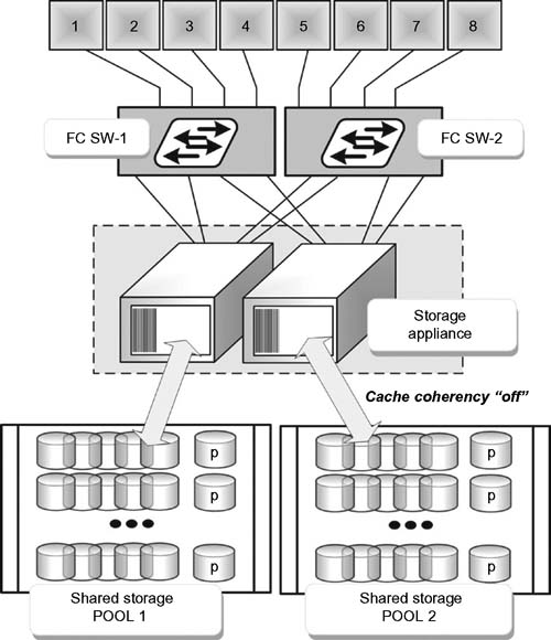
Figure 16.8 Silicon storage appliance fabric multipathing (cache coherency OFF).

Figure 16.9 Local multipathing in the cache coherency OFF mode
Failover
High-availability environments can be categorized into either of two failover scenarios. Generally these failover modes will fall into either a “local storage failover” scenario or a “host-to-host failover” cluster.
Local Storage Failover
A local storage failover scenario will be concerned with only a single host computer and is considered the simplest case. In a mode like that of a direct-attached dual-controller RAID configuration, if a path to either RAID controller is lost, the host may access the storage behind the RAID controller through the remaining RAID controller. This access redirection requires that a process on the RAID system reassigns all of the LUNs to the remaining active controller. It must further redirect data access to the HBA that is connected to the currently active controller.
A local storage failover could be caused by a failure in the interface cable, the HBA, or the RAID controller itself. In normal RAID systems, the LUNs generally must be accessed only through the controller that “owns” them. In the example of a local storage failover mode, only one controller remains active, so it is not possible to load balance the RAID systems.
The storage accelerator appliance, by virtue of its own parallelism, enables a much faster and more elegant failover operation and further permits a load balancing capability unavailable with other storage infrastructure devices. In the dual storage accelerator example shown in Figure 16.10, a single host server is configured with multiple alternate paths to two storage accelerator appliances. This arrangement demonstrates that when there is a minimum of two ports available (shown by the thick lines) and a pair of four port appliances, that up to eight native ports (the combination of both the thicker and the thinner lines) are available for the continued flow of data between the server and storage. Operations will continue even when more than two connections are disabled or are reduced in throughput.
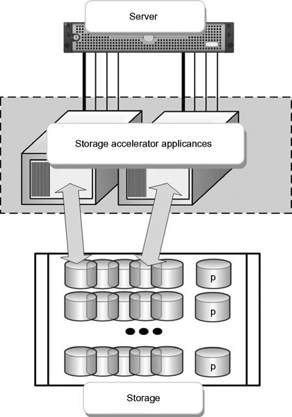
Figure 16.10 Dual storage accelerator appliance provisioned for local failover and load balancing.
In storage accelerator appliances, it may be beneficial to allow the user or the program to turn cache coherency either on or off. In the case where cache coherency is on, all ports may access all of the LUNs. If a host fails, the intelligent storage appliance looks for an alternate path. This path could be to the same media director or through another alternative media director. In an intelligent storage accelerator, there are no failover events that would require the accelerator itself to reassign LUNs. There is no latency in the system because no time is wasted as the alternate path is instantly available.
Alternative Pathing
Alternate pathing software during a failover event may be provided by the host manufacturers themselves or through third party software vendors. These applications are provided at the driver level and allow for extremely fast failover events. The software applications may further continue to permit load balancing should alternate paths to the storage be available.accelerator itself to reassign LUNs. There is no latency in the system because no time is wasted as the alternate path is instantly available.
In telecommunications, this capability is known as “bonding” or “trunking,” a model analogous to disk striping except that it does not require separate LUNs to stripe against. Instead, the host transfers the data as fast as possible using all the available paths, or through the ability to route around a failure using any of the available paths.
Inactive Cache Coherency
If cache coherency is disabled, some software solutions may allow the configuration of a predetermined alternate path should connectivity be lost. For some of the selective operating systems, vendors may provide this functionality in their HBA driver. Should a media director failure occurs, a storage accelerator could automatically reassign LUNs to the alternate media director, creating a completely automated failover.
Host-to-Host Failover Cluster
In the failover of a cluster, the host-to-host failover mode provides for similar local failover capabilities, but further provides support for redundant hosts in the case where there is a catastrophic host failure. In this mode, both hosts require access to the same LUNs, although typically a LUN is “owned” by an active host, with the other host supporting it in a passive mode. The hosts are continually monitored through a heartbeat signal that connects to the redundant host(s). Should the heartbeat disappear, then the passive host takes ownership of all LUNs and it becomes active. When a parallel system is comprised of two storage accelerator platforms, and when media directors are configured, any failover should occur quickly and in a nearly transparent fashion like that of the local failover mode described previously.
A host-to-host failover cluster is shown in Figure 16.11. In this model, load balancing is still employed (shown by the thinner lines). Should increased port connectivity be required, Fibre Channel switches may be added.
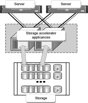
Figure 16.11 Configuration of a storage appliance as a host-to-host failover cluster with high availability (HA) and load balancing.
Workflow Improvement
These new classes of intelligent storage infrastructures provide capabilities that were not available in previous storage architectures. Storage accelerator appliances, which are often modeled with silicon (solid state) disk or RAM architectures, are easily managed, become less complicated, and provide for high-performing and more robust SANs.
Storage accelerator appliances are equally adept at simple storage consolidation, file sharing and highly available fault tolerant environments. Through their parallelism and virtualization capabilities, benefits are achieved that were not previously possible when amalgamating discrete storage devices. Parallelism further enhances the switched fabric by reducing performance obstacles found as a result of switching latency and contention.
The storage accelerator platform can simplify the workflow by providing a single instance of digital content that is accessible by many users simultaneously. An intelligent storage accelerator enables the storage platform to make data writes happen as fast as data reads.
Such implementations streamline the production pipeline as they significantly reduce errors, shorten production time, and enable faster creativity in content development. Combining all these elements in turn reduces both complexities and administrative overhead challenges.
Real-World Performance
Employing high performance storage with a high QoS factor is an absolute requirement when working with real time, high-bit rate video or digital film. Such storage systems, in SAN configurations, now operate at 4-Gbit/second and 8-Gbit/second Fibre Channel; and 10-Gbit/second or 20-Gbit/second InfiniBand. These implementations are critical when operating in high throughput, highdata volume environments such as those found in production or postproduction workflows.
Users should be cautioned that employing high-performance SAN storage and the supporting infrastructure that these systems require can be expensive. Consideration must also be given to scaling limitations associated with concurrent shared workloads that may be accessing. Understanding the QoS of the system and knowing that it can be guaranteed for the workflows desired are crucial in selecting the switches, storage components, and RAID controllers.
Guaranteed Delivery
In real-time delivery workflows, it is not enough to know that a system will deliver say 90% of the I/O requests in less than 400 ms, but the remaining 10% are completely unpredictable—unless you are willing to tolerate dropped frames or periods of black in the video stream. A guaranteed QoS means that a system will never exceed a specified time for a request, regardless of the stream’s content or system loading.
Postproduction editing, compositing, animation, special effects, color grading, mastering, and archiving can be highly collaborative processes. As discussed earlier, improperly configured SAN storage may lack the ability to provide native collaborative workload sharing. Thus, workload sharing is often confined to a smaller high-performance SAN environment when there is a shared SAN file system.
Scaling for Shared SAN File Systems
Shared SAN file systems are typically available from the leading providers of editing platforms. When users scale these shared SAN file systems to mid- or large-sized SANs, there is a potential for the overall system performance to decline rapidly. Performance degradation may be caused in part by the increased load on the metadata controller. In this scenario, the metadata controller becomes incapable of providing the necessary resources to guarantee the data stream for video/film real-time streaming. In order to effectively scale these levels of SAN systems, users must provide dedicated systems to smaller groups.
Systems that are specifically designed to integrate the various server functions with the switches and the storage media, including the metadata server and media directors, can be configured to provide a guaranteed QoS—but these systems will not be “commercially available” off-the-shelf components with random performance specifications. Such systems will need enterpriseclass drives, performance- driven RAID controllers, and managed switches (gigabit Ethernet and Fibre Channel) designed to meet continuous 100% duty cycle operations in harsh, demanding environments.
NAS Solutions
A NAS solution can reduce the costs for collaborative postproduction storage. NAS solutions allow the postproduction storage fulfillment to reach around 80% of the necessary capacity for as much as half the cost of an equivalent storage budget in a SAN. Unfortunately, many NAS systems are still unable to meet the demands of rich-media postproduction for digital film or realtime video. Many traditional NAS systems are incapable or cannot effectively scale in performance or capacity. This results in perplexed operators who must then seek alternative means to complete their work on smaller systems. That work must then later be migrated and merged into other platforms, often continuously throughout the postproduction processes.
Tradition NAS and even some of the clustered NAS solutions are not designed to handle the performance requirements of postproduction. These systems typically must provide both high input/output operations per second (IOPS) and high throughput concurrently, something the majority of standalone NAS systems do not provide. Although it is certainly possible to tune the NAS system for one metric or two metrics, providing the proper balance for all services, at a QoS that can support the production demands, will often come up short of the enterprise’s critical needs and expectations.
As an example, NAS systems tend to have extremely long rendering times with read access times that are much too slow. Write outs also become slower following the completion of rendering, creating bottlenecks that force production workflows to crawl. Another concern is that these storage systems are unable to provide backup services concurrently with production access throughout the day. Prioritization policies fail and the backups move into the off hours further degrading rendering time, which is traditionally done overnight when other activities are subdued. Frequently, the ability to combine rendering and workstation creative activities concurrently causes delays in obtaining approvals or in completing other tasks during the work day, forcing yet another bottleneck into the workflow. The domino effect becomes obvious.
Such performance constraints, caused by the storage system throughput, can lead to application failures or crashes, a direct result of such I/O timeouts.
NAS Performance Scaling
Scaling the performance of a NAS system is yet another critical system issue. While reading the next sections on scalability, keep in mind the three axes of scalability (shown in Fig. 16.12) that need to be balanced both functionally and economically.

Figure 16.12 Three axes of scalability.
When the systems add more clients (workstations), traditional NAS systems tend to experience acute limitations in performance. Growing the number of clients attached to a NAS causes desktop response times to slow to a crawl when opening or saving a project. These performance issues only get worse when meeting the demands of HD (6 Mbytes), 2K (12 Mbytes) and 4K (49 Mbytes) file sizes.
When a NAS system approaches its maximum performance or maximum file capacity, the system often becomes unresponsive. If the system crashes, then the support team has to address a system restart and in the worst case, the recovery of lost or “suspended” data. Should the data be unrecoverable under conventional restart means, then the system must be rebuilt. Any of these tasks can be a painstakingly lengthy process.
At this point of frustration, users often take the approach of implementing more NAS systems. While a potentially suitable short-term fix, it is not a particularly good work-around; it really does not solve the scalability or the capacity problem, and never addresses the bandwidth (throughput) problem. In fact, it simply defers it, creating other problems of its own—known as “NAS sprawl.”
NAS Management
The issues of NAS management do not increase in linear proportion to the size or capacities of the systems—it, in fact, increases exponentially. The management is both physical (e.g., increase in size, space, and cooling) and virtual (i.e., data wrangling). One of the biggest constraints becomes the continual manual, hands-on data migration between systems. The next big headache comes from the continuous recalculations needed for the efficient utilization of the assets, sometimes improperly called “load balancing.”
Low Latency Solutions
An intelligent storage system for postproduction should be designed from the ground up so as to meet the demands and requirements of these forms of workflows. Such systems must further allow for scalable collaboration, high-speed low-latency performance, and the expectations for increased storage capacity.
The intelligent storage platform should be capable of offloading from RAID or other disk management systems some of the performance draining functions found in CIFS or NFS. With the advent of field-programmable gate arrays (FPGA), and solid state disks or RAM caches that are implemented into the silicon, an ultra-low latency for server I/O request handling can be achieved. In this case, latency is defined as the measurement of how quickly a server responds to the clients’ requests; i.e., the lower the latency, the greater number of clients and I/O that can be handled.
Low-latency capability enables the storage platform to be concurrently combined with ingest, rendering, and other workstation activities in support of the overall workflow. These architectures allow systems to handle maximum loads simultaneously through the use of distributed memory, state engines, and parallel pipelines. Parallelism permits systems to process I/O requests at maximum performance limits without service degradation. These high-performance architectures are designed to remove data-flow constraints and eliminate performance bottlenecks especially when employed in large and powerful render farms. The results are faster rendering times with fewer dropped frames and far less rework for the data wranglers.
Scale-Up and Scale-Out
Two terms often associated separately and distinctly are phrases that have as much marketing spin as performance spec. “Scale-up” refers to the scaling capacity within the NAS filer. “Scale-out,” also called horizontal scaling, at a simple level, refers to the clustering of more than two heads in a single image.
Scale-out storage enables commodity storage components to be combined with multiple small, low cost computers either to (a) create an aggregate storage pool or to (b) increase computing power. Both scenarios exploit the traditional models of storage and computer power with the intention that when configured they will exceed the capabilities and performance of single traditional storage arrays or single, high-performance workstations or servers. As the demand increases for storage virtualization, for shared data storage, or for expanded data protection services, this commodity-based scale-out model is being offered by many vendors and is becoming increasingly more popular.
Clusters and grids are both examples of scale-out systems. However, the concept of “scale-out” can apply equally as well to the SAN as it does to those NAS environments from which the advantages of scale-out are more commonly associated.
Scaling Storage Topologies
Scale-out is a term often assumed to be synonymous with NAS. Scale-up is often assumed to be synonymous with SANs. The fact is that scalability is not necessarily a direct function of the storage architecture. Thus, scale-out could apply to all the major storage topologies, as follows:
DAS Scale-Out
The simpler of the storage technologies to manage, directattached storage (DAS) can scale-out to a limited degree such that it increases performance and capacity by simply increasing the HDD count or by adding larger or faster drives. DAS scale-out may be further accomplished by cascading additional control units that can in turn increase the HDD count. However, the drawback is that DAS lacks the ability to provide many of the efficiencies and/or advanced functionalities that make the management efforts simpler or add operational advantage as the storage pool grows.
NAS Scale-Out
Network attached storage (NAS) is the architecture comprised of servers, disks, and storage management software that is dedicated to serving files over a network. Scale-out storage is frequently associated with NAS systems because of their ability to scale to a cluster of NAS nodes. The crucial point here is that the nodes can scale in terms of capacity and performance, either in combinations or as independents, and still maintain a single-system image.
Unstructured data, usually in “file format,” is a huge segment of all the digital storage that is mostly stored on NAS. Unstructured data has outpaced structured data growth, and as a result, has increased the demand for low-cost scale-out storage.
Scale-Out SANs
Scale-out in storage area networking is achieved by creating a scale-out SAN fabric, usually through the addition of more SAN switches and drive arrays. This approach allows users to achieve both increased performance horsepower and storage capacity in linear steps.
For the enterprise, SANs provide excellent scale-out capability that can address their anticipated growth in information storage requirements. Unlike DAS, any excess capacity in the SAN can be pooled to provide for higher utilization of resources as well as advanced functionalities. SAN topologies are implemented to meet differing needs in scaling. They can scale-out through the connection of SAN islands that were built around individual switches to form larger single fabrics. They can use routers to physically connect the switches while logically isolating the fabrics. For virtualized storage, the scale-out principle will often be employed using SANs.
Scale-Up
When a system scales up vertically, it adds resources to a single node in a system. This may involve the addition of CPUs or memory (or both) to a single computer. Scale-up can apply to servers, individual workstations, or storage subsystems.
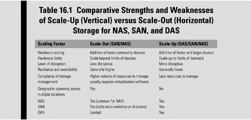
Such vertical scaling of existing systems also enables them to use virtualization technology more effectively, as it provides more resources for the hosted set of operating system and application modules to share. Scale-up means that processors, connectivity, and capacity can be dynamically added in a single unit, and that there can be support for page-level tiering. Often scale-up will intermingle with scale-out, meaning that individual units can be dynamically combined into a single logical system with shared resources, and the storage needs of the servers can then be prioritized and provisioned to form a common pool of storage resources. Table 16.1 places scale-up and scale-out systems in perspective to the various storage architectures of SAN, NAS and DAS.
Page-Level Tiering
The relatively new terminology of page-level tiering lets the organization break up storage data at the page level, rather than at the logical unit number (LUN) level. It moves the data to the storage media that best matches the data’s requirements.
With the ability for a LUN to span multiple tiers of pages, typically when databases grow, there would be tendencies for large amounts of data that would not have been touched in a long time to stay in tier one or tier two storage where the fastest drives are. With this new page-level tiering hierarchy, some pages can now drop to the lowest tier, letting the system match data, at a more granular level, to a particular tier of storage.
Another term, “scale-deep,” is applied when the platform lets organizations dynamically virtualize new and existing external storage systems.
Backend RAID Scale-Up
Scale-up storage can be achieved by employing backend RAID storage. This is where controllers and drives are attached (or added) to the storage subsystem and then virtualized into a single pool or multiple pools. By adding both controllers and storage, capacity scaling results in more processing power for the storage subsystem, which allows for the linear scaling of performance (bandwidth) as well as capacity.
Many NAS filers do not scale the backend RAID processing side of the equation. Hence, without increasing both the RAID controllers and the drives there becomes a point at which there are only marginal returns and where the actual performance declines as the storage capacity increases.
Shared Storage Implementations
This chapter, so far, has looked quite deeply into storage technologies that have helped to support the consolidation of smaller islands of storage, or where the proliferation of NAS or smaller SANs has reached a point where something major needed to be done. In very large, complex data centers and in production facilities that have ebbed and flowed with the demands for creating more with less, these forms of storage solutions make practical sense. In many of the smaller scale facilities, there has been a continuing trend to manage workflows with the same kind of structure as, say, a Windows Workgroup. Every solution has its place, but in the final section of this chapter we will look at how shared storage fits into the workspace and see just how one can make intelligent, cost-effective solutions that solve the issues of storage islands, consolidation, and collaborative workflow.
Examining the Current State of Affairs
As users go out to look for solutions that can fulfill their organization’s needs for storage, and having read or examined as much as possible about NAS, SAN, or DAS architectures, an approach that seems to make a significant amount of practical sense is the deployment of a shared storage platform. In Fig. 16.13, a number of storage subsystems are shown orbiting around a centralized storage system that feeds to or receives from the entities around that center blob.
Around this core you find ingest and playout devices that may input directly to the shared storage or may be used to stage content to or from the other storage devices. The core further supports the preparation of content for the delivery formats needed, including the transcoding operations necessary to present content from the system to the outside.
In a production environment, many of the accesses to or from core shared storage tend to occur when the nonlinear editors are conforming production segments (which are also stored on the core) into finished work. The balance of the peripheral access is focused on ingest, playout, proxy generation, transcoding services, archive, or replication for disaster recovery applications.

Figure 16.13 Typical broadcast and/or production environment with annotations describing key concerns when building out a core shared storage system.
Legacy Status Quo
Many who are reading this book have most likely already gone through round one or round two of file-based workflow implementations. At this stage, the users are probably looking at how to optimize their organization’s workflows. In some cases, there may already be some level of shared storage in place, but they have worked around certain performance metrics by having separate islands of storage that are application specific.
The reasons for these work-arounds often stem from the inability to connect subsystems together because, for example, there was not a file system driver for a particular application, or the file formats were incompatible with one another. Another drawback to having multiple pools of existing storage is discovered when the users outgrow the local storage capacity and must expand the system; this often brings roadblocks that were not recognized when the original systems were installed.

Figure 16.14 Comparative differences between pools of storage connected to a central store (A) versus shared storage connected in a collaborative network-based configuration (B).
Expansion can be a costly experience, exacerbated by having to backup all the existing data, wipe all the storage pools, and then rebuild them with the newer, larger storage systems. The various storage subsystems may have indeed reached their design capacity, limiting the ability to grow the current storage any further and resulting in a “forklift” upgrade with the disposition of all the current storage subsystems.
Workstation performance may also limit the ability to grow the local storage islands (or “pools”). In this case, the avenues available get quite limited. The replacement of the workstation and/or the storage may not yield any further performance improvements and may indeed hinder collaborate workflows altogether. In this case, a solution that improves storage capacity, bandwidth, resilience, and collaboration is in order (see Fig. 16.14).
Benefits to Collaborative Storage
Having everything under a single file system makes a huge improvement in overall system performance. In most first or second generation file-based workflow implementations, many of the tool sets operating on the files were addressed through “watch folders.” This is the place where users magically drop a file into a designated folder and then some other device grabs the file to perform some action on it. Once that task is completed, the file is returned to yet another watch folder where a signal is given to retrieve that file for other uses. Sometimes this watch folder workflow is required only because there is no common single file system available; while for others it is the only way that the third party application will work.
All of this file movement costs something. It may be time, storage space, or a utility that must be purchased. In terms of space, whenever you move a file to a folder you are required to have a duplicate amount of storage space (provided—and recommended—that you want to keep the original file as a protective backup). The more the users can consolidate files into a single central location, the less duplication there is, and the faster and more efficient the workflow becomes. Furthermore, there will be less management of the system when the architecture is based upon a collaborative, centralized storage environment.
In order to achieve true collaborative storage, there will bechallenges.
Challenges to Collaborative Workflow
The main challenges in getting the most out of a collaborative storage model is getting all the devices connected, achieving sufficient bandwidth with the least amount of latency with regard to performance, and addressing expansion or growth in the system. Each of these challenges play off of each other. Conversely, there may be trade-offs necessary to reach one goal that are offset by the capabilities remaining in another.
For example, you may want more bandwidth in the system but it may have to be paid for by a modest increase in latency. Or if an expansion of capacity is a target goal, you may not be able to expand performance at the same time or perhaps even independently.
The center of the thought process on shared storage is not to look at trade-offs, but to look deeper into creative ways to find solutions that deal with the linkage of the systems so that what is achieved in the end is not a compromise, but is something that fits and optimizes for the different categories as shown in Fig. 16.15.
Resilient Storage
The method to accomplish resiliency in a system is one of the big factors in optimizing data availability throughout the workflow. The way that you can achieve this is through arithmetic recovery (as in RAID), or through replication as in duplicated slices of files spread across a high-availability (HA) storage system. In arithmetic recovery, there is not an exact duplicate of the data in the system, but there is a way to recover the data through parity or other means. In replication, the system relies on another set of the data located somewhere on the system that can be used to reconstruct the data set in another portion of the system. The system, in either case, may be a local core shared storage platform or a remote located system or disaster recovery site.
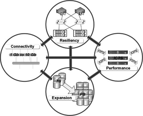
Figure 16.15 The four categories required for building a collaborative and shared storage environment.
Chapter 19 is devoted to resilience and fault tolerance in storage systems and goes into greater depth on those topics as well as virtualization.
Data Access, Repair, and Vulnerability
Users will need access to the data not just when everything in the system is running fine, but also when something has been compromised. This ties in with the discussion about connectivity, whereby more than one data path is available by employing dual network interfaces or redundant switches in a system. Data in the system must have the ability to be accessed constantly.
Additionally, repairing of the data should occur transparently in the background and without user intervention. At the core of any storage system will be spinning disks. These are mechanical devices, and the question is not if they will fail—but when. If a failure occurs in a drive, especially after hours or on weekends when critical “number crunching” typically happens, it should not require an operator or technician to come in and do something just to resume normal operations. Having repairs happen automatically with a “self-healing” system reduces vulnerability by not having to enlist a human to find, diagnosis, and correct by trial and error.
If the system has been optimized for performance and not just for the clients doing their routine day-to-day work, the performance of that repair function will occur in isolation from the user or the workflow. By having the system optimized for resiliency, the organization has reduced the risk of vulnerability.
The key differentiator in a highly resilient, core shared storage environment is being able to keep doing your work without compromise no matter what is happening with the system, and without having to experience any downtime.
Reducing Risk
A means to reduce the impact of a compromise in the systems, whether unintentional or as a result of a planned outage (temporary repair or update), is through the practice of distributing the data across a grouping of storage components that mitigates the risk of a failure or reduction in performance. In this example, when data is ingested into the system, it is first spread across the storage platform such that if any portion of the system fails, the balance of the data is not compromised, and all of the data is recoverable. The diagram (Fig. 16.16) shows a replication scenario, which has then been bisected such that if a section loses connectivity or an element in one slice needs attention, the remainder of the system can pick up the balance of the workflow until connectivity is restored or repairs are completed.
Connectivity
Having the ability to interface between all the subsystems is essential to the successful implementation of a core shared storage platform. If each of the systems are unable to easily and efficiently exchange data, the entire purpose of implementing a shared storage environment is negated.
The system, as a whole, should provide for sufficient network and storage connectivity to allow it to fail over to an auxiliary path. Should any part of a system fail, the question becomes, “What sort of access is available so that each of the clients attached to the system do not lose their ability to continue doing their work?” Of course, in this case, resilience is not the only factor to contend with, but system performance now also plays a role in terms of fulfilling the expectations that the system will continue to meet its target objectives. This can be achieved by building in redundant fabrics to interconnect the storage components, which also are connected redundantly to each of the clients attached to the system.
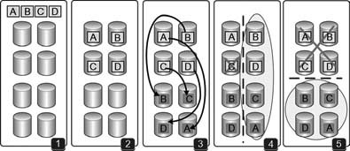
Figure 16.16 Resiliency through division and distribution of a shared storage environment that maintains access in the event of a failure or when a portion of the storage system must be maintained or updated.
Replication and resiliency model
(1) Contains an empty store plus data sets A-B-C-D. This data is written into four sectors of the store as shown in (2).
(3) Depicts the previously written data sets replicated to another area of the store, giving a complete duplicate set of data from which a full set of the data could then be reconstructed if any section of the store failed.
(4) Shows what happens if data “C” is compromised. In this situation, the data could be completely reconstructed from the primary and the replicated sets – shown by the oval on the right side of (4). Should a serious defect cause the entire top section of the store to fail
(5), the replicated section could be used either to deliver data or to aid in reconstructing the data once the top portion is restored. In normal operation, the replicated data provides for increased bandwidth and performance.
This kind of configuration not only provides for resiliency in terms of connectivity but also improves performance by allowing parallel access to two halves of the system continuously when it is in full 100% operational mode. Furthermore, any design should allow for the use of all of the tools in the system, regardless of if those tools are part Windows-based and part Mac-based or even Linux-based.
When planning the system design be certain that all of the foreseeable needs can be met, especially now that the application world is so multiOS centric. This investigation includes looking beyond just the applications you are using in house today; it also means addressing both 32-bit and 64-bit apps as well.
Fabric or Network?
Not long ago the means to performance, bandwidth, and reduced latency dictated the deployment of a Fibre Channel-based storage architecture. In nonlinear editing systems, this belief still exists. That is not necessarily the case any longer. Having an infrastructure that is based around network protocols, such as Ethernet, is essential to make today’s evolving filebased workflow and shared storage environments practical and economical.
This is not just 1 Gbit Ethernet connectivity; it goes well into ranges above and below that data rate. Wireless connectivity to iPads, for example, helps allow users to work in a multiplatform, nonfixed base environment. Building around a network-based infrastructure allows the organization to have more clients connected and to work in ranges from wireless to multiple 10 Gigabit data ranges. Having a sufficient backbone with enterprise-class switching or routing as the foundation will be money well spent from the beginning. Replacing a backbone mid-operation is simply not an option.
The cost versus performance trends are clearly headed in the direction of Ethernet (or IP) connectivity. The sheer volume of Ethernet-based equipment being manufactured and installed today versus Fibre Channel offsets any hope for reducing the cost of even an equivalent smaller scale Fibre Channel storage infrastructure. Faster drives coupled with technologies that ride over or under the Fibre Channel banner are making it very practical to build out on alternative topologies.
Bandwidth
Bandwidth, in the perspective of collaborative shared storage, really should be separated from the topic of latency. In this discussion, bandwidth may pertain to the ability to sustain high-data transfer rates. From another standpoint, there are fundamental needs to get data from point A to point B and if sufficient bandwidth is not supplied then the ability to get work accomplished could be severely impacted. At this point, these decisions really become ones that are more business- related than equipment selection-related. Although most of the issues can be solved through technology-related solutions, the organization’s capital should be utilized first and foremost is in support of the business and productivity requirements.
In the world of file-based workflow, the discussion can quickly turn to “How fast can I get a file to a given point?” and “What am I willing to pay?” to accomplish a certain task in a certain period of time. In these situations, it may be practical to increase connectivity by adding a second network interface card (NIC) to a compositing station and connect it to shared storage because by doing so “Bob” gets his work done twice as fast.
The capacity solution may not be as simple as just adding another NAS head to the system, a solution deemed to be less costly than building out a shared storage system. Adding a NAS head solves a short-term issue, but in terms of performance (led by bandwidth), it turns out to be rather limiting unless the NAS head is a performance-based, intelligent storage subsystem like those discussed much earlier in this chapter. In many areas, adding a NAS head for the purpose of gaining additional access (i.e., bandwidth) is not necessarily the suggested solution for something that is performance sensitive; but it also is not the only way to go.
Leaving the NAS head in as an optional solution for an access point, such as in legacy architectures, has its own potential set of values. It could indeed be more practical to utilize the additional storage as an access point for FTP, NFS, Apple Filing Protocol (AFP), or Samba. The NAS solution may further open the door to a shared storage system for those in-place legacy systems, acting more like a gateway than it does a storage island. This is not to suggest that subsystems be added such that more bottlenecks are created; however, the concepts are certainly worthy of consideration from a flexibility standpoint.
Direct Access
What is really desired is the ability to have direct access to the files, content, data, and others in the workgroups so that you mitigate latency while also gaining parallel access to the shared storage elements. Of course, this requires that the system components have the capability to take advantage of parallel access so that the additional layer of latency is constrained. This is akin to the earlier discussion about adding a second NIC to the workstation, or the redundant Ethernet switch to improve throughput by means of channeling data directly from a workstation to shared storage.
From a latency perspective, we are now switching away from the “How much raw throughput can I get?” question to a scenario that matters much more to those nonlinear editing platforms that are connected to a central store for the purpose of edit-inplace. Nonlinear editors (NLEs), by the functional nature of their workflow, are not moving through large sequential files (like an ingest point or playout server does), but rather the NLEs are “cutting” together multiple elements that involve taking small bits from one area of the store and then more from another part and assembling them into a single contiguous file that will be sequential in nature at the time the editing is concluded.
To exemplify the complexities of enabling a collaborative workflow, there have been applications from some vendors that have actually not allowed both SD and HD files on the same RAID structure because it impaired the performance of the opposite format from which it was working in. Such vendors were obviously not too cognizant of the practical aspects of shared storage environments and would actually force the take down of the RAID system and require it to be reformatted in order to meet the required workflow objectives specific to their applications and the format of the files (resolution and compression format wise).
In any system that requires the interplay of various file formats and structures, it would be entirely impractical to force the reconfiguration of the storage system just to address an application inconsistency. In a large system, you certainly do not want to be restriping or relaying your data on a file system. The system must be content media aware so as to mitigate the configuration issues that eat away at productivity while simultaneously reducing performance.
In today’s world, constraining the storage platform would be almost unheard of. However, looking forward, if your organization has any potential to do 1080p60 production, or stereoscopic (3D) or even 2K or 4K postproduction, then not having the capability to scale-out the storage could limit the overall system functionality and prohibit working in those larger dimensions.
Media Affinity
Digital video and audio likes to be handled in the domain that it is most accustomed to work in. A/V content by its very nature has an affinity to being recorded or played back at its real-time rate. If you can identify what the particular data structure is, then when it is written into the system or copied or moved, you can arrange the data so that it is laid out with certain chunk sizes. Later, when you access that data in the file system, it has already been optimized for the way the system will be reading or writing it, based upon the data’s affinity for real-time use.
What the system is actually being optimized for is I/O operations per second (IOPS). This is the real battleground that is shaping up in media operations, that is, the system must be tuned up to address the number of IOPS needed for the application, which the storage system must support. In terms of current technology, this is where the solid state drive (SSD) is becoming more applicable in that it allows short-term data to be moved very quickly to storage where it will be repeatedly accessed in smaller chunks during the production workflow process (for more about SSD technologies, refer to Chapter 7).
These kinds of applications must be handled quite differently from large bulk transfers of sequential data, like when a system is in a playout-only mode.
Performance Tuning
Storage system architectures need to posses content awareness capabilities. By this, we mean that through the use of structural metadata (explained in Chapter 13) the chunks of data can be categorized so that they may be placed onto optimized storage sets that best address the IOPS requirements.
Storage systems will be “tuned” to meet the various media read and write affinities. If your system is agile enough to address the placement of data based upon the structural metadata it reads, then the hidden management of the data types can be optimized without the user or the administrator continually shuffling the data between storage containers.
Having a system that allows for striping and parallel access to the storage systems helps to address the performance tuning equation. Through the use of buffering and IOPS tuning, controlled from the structural metadata information obtained by the file system, the organization can adjust the performance of the system to meet either the workgroups that need the access or to allow for changes to be made in bandwidth or latency based upon what the organization requires for its current workflow.
As an example, looking at three file types of A/V media, one can see that these have three distinct and radically different dimensions:
•Video: .MOV at 220 Mbits/second, ProRes/DNxHD, file size = 1.5 Gbytes, slice size = 2 to 8 Mbytes/slice
•Graphics: .PSD image size 4K × 2K, 16 bits per channel, file size = 100 Mbytes, slice size = 1 to 2 Mbytes/slice
•Audio: .AIFF at 24 bit, 48 kHz sampling, file size = 50 Mbytes, slice size = 256 to 512 Kbits/slice
Placing all of these files into the same, highest-sized storage would not be optimizing the system performance based upon the media type. Instead, the storage architecture and the system IOPS would be arranged so as to meet the requirements of each media type, allowing the specifics of each file type to be optimized for the workflow it needs. This means the audio files would be segmented to the digital audio workstation (DAW) clients possibly on their own VLAN so that these smaller slices are not bogged down by, for example, the 2–8 MByte slices of full motion video. The same goes for the graphics system, where access is far less frequent, so the Mac workstations outfitted with Adobe Photoshop can get the best IOPS performance when needed.
Expansion
Consideration must be given, at the onset, to the requirements of growing the shared storage environment. When getting a quote for a shared storage system, do not just stop with the cost question. Understand what the long-term implications of starting with that particular solution and then having to grow it over time actually means. Know what the support costs will be over five years, and how the supplier intends to support the system once the initial technology becomes “legacy” technology.
Look closely at the options for expansion. Ask the vendor what the limitations are and in what increments can expansion occur. Will there be a brick wall whereby no more storage can be added without a forklift upgrade being required? Know if the drives in the system can be upgraded, or if you want to upgrade them, can you mix drive sizes without having to offload all your data and then reformat the arrays.
Flexibility and options are the keys to a cost-effective longterm growth option. It may seem impressive to have saved 30% on a system price at the time it was first implemented only to find you need to spend all that, and more, just to expand to the next plateau of capacity or performance. This may even mean the freedom of switching from rotating media to solid state media without necessarily having to replace or abandon the existing drive chassis.
Users should be able to add capacity but not be bound to use a particular increment of size. If you want to add a single unit of storage, you should not be forced to double the size of the entire system because of some unforeseen issue or ill-conceived architecture that kept incremental growth from occurring. When you add volumes to the system, you do not want that to sit empty while you gain no bandwidth performance increases. What is desired is a system that will redistribute all data in the background when new volumes are added to balance out the new capacities and spread the data across all of the shared storage. This alone will allow for increased performance through the effects of increased bandwidth and/or parallel access. Furthermore, by distributing the data across more capacity, this increases the number of responders that can handle more requests for access, in parallel, which in turn reduces latency while increasing bandwidth.
Storage Scaling and Management
As you move onto the next chapters, it will become evident that the management of storage, especially for media content, is becoming a science that goes well beyond traditional IT technologies. Vertical and horizontal scaling for capacity and performance are being addressed by the higher end specialty storage manufacturers that provide solutions to the massive file sizes and collaborative working environments found in the production of modern digital media films, videos, and effects.
Further Readings
An example of test results, which also depict configurations and benchmarks of various intelligent storage system providers, and covers the period beginning around 2001 through 2008 can be found at http://www.spec.org/sfs97r1/results/sfs97r1.html.
Selected providers of intelligent, high performance storage include: NetApp (http://www.netapp.com) Quantum StorNext (http://www.quantum.com/) Data Direct Networks (http://www.datadirectnet.com/) Isilon (now part of EMC) (http://www.isilon.com/ and http://www.emc.com/) Hitachi Data Systems (http://www.hds.com/)
Selected providers of shared storage architectures for broadcast and production media operations include: Omneon (part of Harmonic) (http://www.omneon.com/) Grass Valley (http://www.grassvalley.com/) Harris (http://www.broadcast.harris.com/productsandsolutions/Servers/) Seachange (http://www.schange.com/)
Further industry information and comparative analysis regarding scale-up and scale-out storage can be found at http://www.enterprisestrategygroup.com/2010/06/scale-out-storage/.