17
SCALABILITY, EXTENSIBILITY, AND INTEROPERABILITY
Storage networking grew out of the need to scale storage capacity and increase performance over conventional direct-attached storage (DAS) systems. Network-attached storage (NAS) and storage area networks (SANs) provide the avenues to extend the practicality, usage, and reach of storage systems, as well as to enable the interchange of information between similar and/or dissimilar platforms through interoperability. The three terms that head this chapter, “scalability,” “extensibility,” and “interoperability,” impart a number of concepts and definitions related to storage, systems, and performance.
Accompanying these three major headings are additional prerequisites that round out the considerations for storage networking: flexibility, reliability, availability, and accessibility. When these are harmonized with the first three characteristics, a set of requirements necessary to support storage networking is created.
This chapter defines their meanings, how and why they are important, and what their impacts are on networked storage systems.
KEY CHAPTER POINTS
•Defining scalability, interoperability, and extensibility as they apply to storage and the interchange of media-centric data
•How open standards versus formalized standards impact implementations of storage systems
•How networked storage systems can scale
•How performance metrics (e.g., MTBF) for mechanical disk drives and flash- based solid state drives are derived
SCALABILITY
Growth is the most common way that a system changes. When growth can no longer be achieved either practically or economically, the system becomes unusable or obsolete. Factors that limit the growth potential in a storage environment include the ability to record and process all of the information desired. Providing a suitable and economical means to hold the vast and ever increasing collection of digital information that an organization creates is more than just a matter of adding storage capacity. The other end of the storage chain requires that these collections must also be accessible.
Scalable solutions that allow for the expansion of data repositories without interruptions to the services they provide are essential in a storage networking environment.
Performance
Providing for a system that is scalable also implies that the system’s performance will scale accordingly. The advent of 1, 2, 4 and 8 Gbit/second Fibre Channel (FC) and the deployment of 10 Gbit/second Fibre Channel over Ethernet (FCoE) have shown that storage area networks (SANs) can intrinsically be designed to scale in the data transfer, performance, and capacity domains.
Integrating the lower speeds with the higher speeds not only extends the performance of existing data storage infrastructures but also permits the entire system to scale as new technologies and increased storage requirements demand. One of the emerging areas that is allowing scalability and performance increases to happen is the combining of multiple switches, routers, or fabrics to permit a wider throughput of data, but in a means that reduces traffic congestion in storage networks.
Inter-Switch L inks and Trunking
Fibre Channel networking uses a component called an interswitch link (ISL) to add extensible and scalable performance increases to the SAN fabric.
In the late 1990s, ISL was introduced as a method of encapsulating tagged local area network (LAN) frames and then transporting them over a full-duplex, point-to-point Ethernet link. At that time, the encapsulated frames would be token-ring or Fast Ethernet. The frames were carried unchanged from transmitter to receiver.
ISL carries data “hop-by-hop” as compared with “point-topoint” links, thus neither the Fast Ethernet nor Gigabit Ethernet constraints of 1,500-byte data frame size are applicable. In this application, ISL may be used to transport the far-larger 18 Kbyte token-ring frames (or alternatively, 100-byte packets). Ethernetbased ISL may be carried as Fast Ethernet on Category 5 (or 5e) copper cabling or fiber-optic cabling as its transport medium, allowing 100 Mbit/second to GigE speeds between switches and servers.
ISLs join FC switches through their E_Ports, which are similar in purpose to the uplink channel in an Ethernet switch.
Cisco Systems employs a proprietary Cisco Inter-Switch Link protocol that maintains VLAN information as traffic flows between switches and routers, or between different switches. ISL is Cisco’s VLAN encapsulation method, which is supported only on Cisco’s equipment through Fast and Gigabit Ethernet links. The size of an Ethernet-encapsulated ISL frame may start from 94 bytes and increase up to 1548 bytes through the additional fields (overhead) that the protocol creates via encapsulation. This implementation of ISL adds a 26-byte header that contains a 15-bit VLAN identifier and a 4-byte CRC trailer to the frame.
ISL functions at Layer 2 (the Data Link Layer) of the OSI model and is used in maintaining redundant links. For the SAN, ISL technology optimizes performance and simplifies the management of multiswitch SAN fabrics.
ISL Trunking
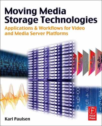
ISL functions at Layer 2 (the Data Link Layer) of the OSI model and is used in maintaining redundant links. For the SAN, ISL technology optimizes performance and simplifies the management of multiswitch SAN fabrics.Combining multiple ISLs in a logic group is called ISL Trunking (see Fig. 17.1). These are generally software applications that simplify fabric design, lower provisioning time, and extend the growth of the storage platform for data replication or remote backup sites by enabling 10 Gbit/second Fibre Channel transfer speeds over dark fiber using dense wave division multiplexing (DWDM).
Brocade employs its version, which they call “ISL Trunking” as an optional system for small- to mid-size data centers whereby when two or more ISLs are used to connect two switches, the switches then automatically group to form a single logical ISL. This application is designed to significantly reduce traffic congestion by combining ISLs in 1, 2 and 4-Gbit/second switches (with the appropriate directors), providing a trunking throughput from 4 Gbit/second to as much as 32 Gbit/second. Using fiber optic transmission, similar forms of technology allowed multilane 10-Gbit/second fiber optic transmission to scale upwards from 40 to 100 Gbit/second through the utilization of IEEE Standard 802.3ba-2010.
To balance workloads across all of the ISLs in the trunk, each incoming frame is sent across the first available physical ISL in the trunk, preventing transient workload peaks, which would otherwise impact the performance of other portions of the SAN fabric. Through a technique called Dynamic Path Selection (DPS), fabricwide performance is automatically optimized (i.e., load balanced) to find the most effective path through the switching network. Thus, ISL Trunking reduces bandwidth that might otherwise be wasted by inefficient traffic routing.
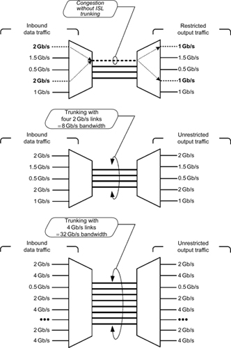
Figure 17.1 Inter-switch link trunking delivers packets in order and increases bandwidth utilization by managing congestion through dynamic load balancing.
Dynamic Load Balancing
Management processes must ensure that delivery of the data is “in order,” so that the system is reliable even if a line in the trunk fails. The system is dynamically load balanced when there are significant differences in the amount of data handled through a lower speed switch versus a higher speed channel. Dynamic load balancing, used in clustering, ensures that the system bandwidth is not wasted.
Backbone Fabric
Fabric backbones, also called backbone fabric (BB-fabric), are highly robust network-switching platforms that are designed for the scaling of the enterprise-level data center. When machines are employed in systems that operate on a fabric backbone, each machine will be comprised of components that combine performance, scalability, and energy efficiency to ensure system reliability and performance while protecting the investment made by the enterprise.
The backbone fabric enables scalable Meta SANs by the networking of multiprotocol routers that connect to the backbone fabric via the E_Port interfaces, a standard Fibre Channel mechanism that enables switches to network to each other.
Multifabric Communications
A collection of all devices, switches, edge and backbone fabrics, logical SANs (LSANs), and multiprotocol routers that make up a physically connected but logically partitioned storage network is called a Meta SAN. In a data network, one would simply call this “the network”; however, additional terms are required to specify the differences between a SAN as a single-fabric network; as a multifabric network without cross-fabric connectivity, as in a “dual-redundant fabric SAN”; and as a multifabric network with connectivity or Meta SAN. Additional information about Fibre Channel and fabric communications can be found in the Appendices on the companion website for this book.
Logical Storage Area Network
Another concept that enables scalability is a logical storage area network that spans multiple fabrics, called an LSAN. The LSAN, along with LSAN zoning, was introduced as a trade name implementation by Brocade in the mid-2000s. The path between the devices in an LSAN can be local to an edge fabric or cross one or more multiprotocol routers and up to one intermediate backbone fabric. LSANs are administered through LSAN zones in each edge fabric. An LSAN zone is a mechanism by which the LSAN is administered where a multiprotocol router listens to the two attached fabrics for the creation of matching LSAN zones on both of those fabrics. When it occurs, a phantom domain is created, and the appropriate Fibre Channel Network Address Translation (FC-NAT) entries are inserted into the name servers on the fabrics. LSAN zones are compatible with standard zoning mechanisms.
Virtual Storage Area Network (VSAN)
The VSAN is a dedicated network of isolated devices, physically connected to the same fabric, yet appearing to be an independent fabric. The VSAN promotes improved availability, scalability, and security. A VSAN creates independently managed groups of fabric resources within the broader fabric, thus reducing cost by eliminating stranded resources. VSANs increase administrative scalability, while reducing risk through the limitation of access to specific VSANs.
A VSAN may have access control to other fabric resources, such as access to remote storage or shared network facilities. From a protocol perspective, the VSAN can actually appear independent through the creation of multiple processes tuned to particular needs—a function not possible in the LSAN.
The VSAN will use an independent management domain within the broader fabric that includes an externally assigned subset of the fabric’s physical resources. The approach is used by Cisco Systems and allows traffic isolation within designated portions of the network. The subscribers to that particular portion of the network may be added, removed, or relocated without the need to physically change the network layout.
Flexibility
There are differing ends of the spectrum that defines storage flexibility. Each segment of that scale is dependent upon the size of the organization, the growth expectations near term and long term, the applications for the storage, and the level of financial commitment the organization has at the initial deployment and further on during the life of that storage system.
Flexibility is somewhat of an intangible requirement that is an offshoot driven by many of the topics discussed in this chapter. As for the categories of storage, when the organization is large, it might take an “enterprise storage” approach. If it is a small boutique using individual “PC-based” storage with internal drives, a small NAS or possibly something as simple as an external USB or Firewire-attached drive is sufficient for their expansion. If the growth expectation is uncertain, then “cloud storage” might be applicable (see Fig. 17.2). And of course, the public cloud storage services that have emerged are built on scale-out platforms, and only a selected group offers the enterprise features needed for growth and performance.
When the organization operates in a shared file structure where many need access to any or all of the data at any time, a shared-disk cluster configuration or high-end enterprise-class storage like a NAS or a SAN may be required. When databases or rich-multimedia applications require constant access, then the requirements would include high performance and highly available storage that allows for multi-attached data sharing from a single volume of LUN across multiple nodes in a cluster.
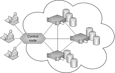
Figure 17.2 The basic “cloud” storage solution for databases and other file storage applications.
This latter example would justify the up-front costs of a highly expandable, single file system-based architecture, which provides the flexibility to add storage or rearrange the configuration almost on the fly.
Shared-Disk Clustering
Smaller offices or independent boutique media companies who are unwilling to pay for high-end storage may rely on PC-based storage or a small-scale NAS array to satisfy their applications. An approach that does not involve cloud storage but could be applicable to these small- or medium-sized operations and provide a reasonable amount of scalability is shared-disk clustering. Clustering has many dimensions and many meanings but generally may be associated with three configurations called shared disk, mirrored disk, and shared nothing (refer to Chapter 18 for a thorough look at clustering).
In the broadest sense, network clustering connects otherwise independent computers and allows them to work together in a coordinated fashion. The hardware configuration of clusters varies substantially depending on the networking technologies chosen and the intended purposes of the system.
One approach to clustering utilizes central I/O devices accessible to all nodes within the cluster. These systems are called shared-disk clusters and will utilize central I/O devices that are accessible to all the nodes (i.e., the computers) within the cluster. The I/O involved is typically disk storage utilized for normal files or databases. A shared-disk cluster relies on this common I/O bus for disk access but does not require shared memory. Since all nodes may concurrently write to or cache data from the central disks, a synchronization mechanism is employed to preserve coherence of the system. The mechanism uses an independent piece of cluster software known as the “ distributed lock manager” to achieve consistency and to prevent random file associations and orphans that might be assumed as the correct file but in fact may be a broken or incomplete version that is unknowingly wrong.
Shared-disk clusters (see the example in Fig. 17.3) support high levels of system availability. Should one node fail, the other nodes need not be affected. Higher availability comes at the cost of a somewhat reduced performance factor due to the overhead required in using a lock manager. There are also opportunities for potential bottlenecks when employing shared hardware in all cases, but shared-disk clusters compensate for this shortcoming by providing relatively good scaling properties.

Figure 17.3 Shared-disk cluster using Fibre Channel for the shared storage portion and an Ethernet switch with NICs for server connectivity.
Accelerators
Today, storage solutions can come in many flavors. This book discusses many of those systems, and with technology what it is, we see there are new approaches to storage functionality being developed all the time. When users of storage systems begin to see performance deficiencies due to excessive access, reduced availability, or limited capacity, they are faced with making some choices. One of those is to replace the storage platform entirely; another is to augment it with capacity, convert DAS to NAS, or implement a SAN solution.
Another option is to employ an accelerator cache. These outboard server-like additions function as an I/O throttle that manages the bottlenecks that conventional disk drive controllers cannot. By removing I/O bottlenecks, system performance is increased, which in turn reduces the notion that the storage system is slow.
Accelerators may come in the form of card-based additions to servers, but today they are typically external self-contained units that employ solid state disk (SSD) devices that are capable of delivering data upwards of 3 Gbytes/second. SSD devices (see Chapter 7) reduce the latency impacts associated with head positioning or seek times. The resulting read-write operations are hundreds of times faster than conventional spinning disks. Although such stand-alone accelerator devices are well suited for small capacity databases or email queues, they are not necessarily appropriate for applications that continually require shared access such as those of an editing or graphics platform that uses rich media.
However, for high performance and highly available intelligent storage platforms, sophisticated accelerators are often directly built in to the product.
Array Accelerator
An array accelerator uses an intelligent read-ahead algorithm that anticipates data requests and reduces wait time. The algorithm detects sequential read activity on single or multiple I/O threads and then predicts which requests will follow next. The data is then gathered and stored in the high-speed cache of the array accelerator. As soon as the data is requested by the operating system, it is delivered at as much as 100 times faster than a disk can deliver the data.
An array accelerator cache capacity is by default divided equally between reads and writes. To improve performance, the storage system administrator can balance or tune up the cache if the applications have significantly more reads than writes or more writes than reads. The optimal ratio is application dependant, which is sometimes the reason why separate servers may be employed with separate I/O functions, especially in enterprise- wide media management operations.
As a preventative measure, when a random access pattern is detected, the read-ahead algorithm is disabled. Using the readahead algorithm with random I/O will slow a system down, effectively rendering the value of cache detrimental instead of making the storage processing faster.
Accelerators will throttle according to the system data flow. When the disks are busy, new writes are stored in the cache and then written to the disk later when there is less activity. This feature is called “write-back” or “copy-back” cache. Some of the smaller blocks can usually be combined into larger blocks, resulting in fewer but larger blocks being written to the disk, thus improving performance.
Accelerators also optimize the storage system by improving latency and throughput, which can lead to reduction in the number of disk spindles or shelves required and reduces cooling, power, and rack space as well.
The take-home point about flexibility is that the storage systems of today are far more adaptable to users’ needs than a decade ago. Going beyond the elementary plug-n-play concept at the interface level, it means, for example, that if a storage system employed just two years ago seems like it has run out of horsepower, there may be alternatives such as accelerators or repurposing that can help ease the financial impact of a wholesale replacement or retirement.
Reliability
As per the definition provided in IEEE 90 (Standard 610.12-1990), “reliability” is the ability of a system or component to perform its required functions under stated conditions for a specified period of time. There are no specific definitions for “high reliability” because it becomes more relative to the parameters of “time period” and “required functions.”
Developing highly reliable high-performance storage architectures requires consideration of both the performance and the reliability characteristics of each storage type or element in the overall solution. Manufacturer specifications will report reliability data for all their respective devices. These include mean time to failure/mean time to replacement (MTTF/MTTR) and drive life estimates. Most of these reports cannot be faithfully applied to determining failure modes or failure rates in high-performance storage systems.
A more meaningful perspective would be to consider the true reliability of a system when looking at real-world failure rates with weighting factors including the age of the product and the operating conditions, such as OPS (operations per second) and the randomness of those operations.
Mechanical or Solid State D evices
Memory and storage components can be divided among a sample of mechanical devices (hard disk drives, CD, DVD, and Bluray drives) and solid state devices (flash-based and DRAM-based solid state drives). For the highest performance applications, the use of DRAM-based SSD can provide the lowest cost and highest reliability.
Although the reliability continues to improve with spinning magnetic disk technologies, the question is not about if it will fail, but when will it fail. Mechanical devices will inevitably reach a point where one of the components will fail, rendering it useless.
Optical-based drives, though their media is more tangible than magnetic-based storage, have physical limitations that follow the same story as their magnetic counterparts. With that, the care of the optical media once out of the drive environment becomes the relative factor in determining the life and reliability of the storage medium.
Data tapes, such as Linear Tape Open (LTO) and other legacy linear tape formats, have a twofold risk not unlike that of the optical-based medium. If properly maintained, both physically and logically, the linear digital data tape formats can be very reliable long term.
Optimization Using a Tiered Approach
Today, the better solution to overall media management reliability from the storage perspective involves a hybrid mixture of both magnetic spinning disk and solid-state/flash-based storage. By tiered approach, we mean the distribution of the data is spread among a variety of systems based upon access requirements, security, redundancy, longevity, and performance.
The ultimate goal of any solution targets an objective of best reliability coupled with the highest performance and the lowest total cost of ownership (TCO). The TCO must consider costs of maintenance and ongoing support including the routine replacement of media or components over the expected financial and technological lifetime of the storage system.
Mean Time Between F ailure
The life expectancy of any product is often considered of paramount importance to its value in a system. Hard disk drives have always been classified as a component with a long life cycle when used properly and in a consistent manner. A frequently cited reliability term used to classify hard drives is the “mean time between failure” (MTBF), also called “mean time before failure.” Ironically, MTBF becomes a nearly unrealistic statistic when applied to hard disk drives (HDD). Even the idea of a mean time “between” a failure is nearly ridiculous because once a hard drive fails, it is nearly 100% certain it will not fail again; thus, there is no “between” the first and second failure.
Nonetheless, typical MTBF specifications will be in the 1 million hours range (give or take a hundred thousand). This, even at 75% run time, approaches between 80 and 90 years before a drive fails. The hard drive has only been in existence (commercially) for about half a century, so this statistic is about as applicable as predicting the number of drops in the ocean at any given instant (and maybe as valuable).
In all fairness, most storage experts will admit these values are only theoretical and will not provide a true indicator of the life expectancy of the HDD. In reality, for a large population of a given particular drive, this value is used to determine the expectation for an annual failure rate, also known as the annual replacement rate (ARR) in percent, based upon 8760 hours in a year divided by the specified MTBF:
8760/MTBF = ARR%
For the HDD with the median 1 million hour MTBF (at a 75% run time), this becomes a 1.2% nominal annual failure rate. A flash-based solid state drive (F-SSD) will have an MTBF of 5 million hours, but given they are powered up at all times, their run rate is 100% and their ARR would be 0.18%. It must be noted that both F-SSD and HDD will have known “wear-affected” failure modes that will seriously alter the ARR, and there are plenty of real-world statistics available to validate this.
Failure Classification
MTBF is often quoted without providing a definition of failure. Even when defined, the relative impact to an overall system makes the failure postulation ambiguous. To address this ambiguity, it can be argued there are two basic postulates of a failure:
•Postulate one—the termination of the ability of the device, as a whole, to perform its required function constitutes a failure of that device.
•Postulate two—the termination of the ability of any single component to perform its required function, but not the termination of the overall capabilities of the device, as a whole system.
For decades, disk drive arrays have been constructed in such a way that if a redundant disk (RAID—redundant array of independent disk) in that array fails, the failure will not prevent the entire array from performing its required function, that is, the supply of data at any time. However, the disk failure does prevent a component of the disk array from performing its required function of supplying storage capacity. Therefore, according to the first postulate, this is not a failure; but according to the second, it is a failure.
The same could be said about the power supplies in a main and redundant operation, a mirrored set of RAID arrays, or a local and remote disaster recovery site. Nonetheless, on an individual basis, the HDD failed, rendering that particular device useless and thus a failure.
Environmental Impacts on Reliability
One must consider the applications for which his/her devices are used in and the environments in which they are placed, in order to account for the true failure rate of the device. One must consider the length of time the device has been in service and the usage properties for that device in that environment.
Secondarily, once must also account for the quantities of devices in that application and the type(s) of storage configurations. Then, equate that to the entire solution to extrapolate the probability of a data loss in the storage array based upon empirical reliability data.
It goes without surprise that there can be a comparatively high replacement rate for those storage devices that are not kept in a clean room environment or in the case where the vendors do not test their products in a real-life world such as those found in a data center, where heat, dust, vibration, or noise are real factors.
Failure Rates over Time
When looking at a large sample of HDDs over the course of many varying applications in an approximately equal number of differing locations, you begin to see that HDD reliability curves take on a rather consistent form. During the initial period of the sample set, a certain number of devices will exhibit an early failure mode (infant mortality). A high number of drives in this sample set will perform consistently and reliably over the full life of the sample set. Toward the end of the statistical life of this set, drives will begin to wear out and show higher failure modes until all but a few of the samples eventually quit functioning.
Thus, in the real world, the failure rates of the HDD are mostly related to the age of the drive.
Workload Impacts
How a storage system is utilized is one of the factors not typically considered in developing a particular storage system. Without evaluating the real-world failure rates based upon age and workload, any storage system design may incur a high degree of risk to data loss. Thus, most systems that are sold by the premier storage industry manufacturers will carefully select the components in their systems and analyze the real-world applications for those components before signing on to a system deployment contract.
Accelerated Life Testing
Stress testing is a method of checking, statistically and actually, how or when a device might fail. When a drive system is put into consistently high rates of random access, such as in a nonlinear video editing (NLE) platform, the drives’ mechanical systems are subject to stresses that are quite different from those of lighter IT-based, transactional database, or structured data applications. High-performance computing environments will have a similar effect to that of a NLE-based operational pattern. In the NLE or high-performance world, the life of the drives is shortened considerably versus the IT-based environments.
Accelerated life testing (ALT) is necessary because of the product development and market life cycle typical to high technology products. ALT involves the acceleration of failures with the single purpose of quantification of the life characteristics of the product at normal use conditions. ALT can be divided into two areas: qualitative accelerated testing and quantitative accelerated life testing.
Qualitative accelerated testing involves the engineer identifying failures and failure modes without attempting to make any predictions as to the product’s life under normal use conditions. Quantitative accelerated life testing (QALT) finds the engineer interested in predicting the life of the product using life characteristics such as MTTF or B(10) life at normal use conditions, from data obtained in an accelerated life test. QALT consists of tests designed to quantify the life characteristics of the product, component, or system under normal use conditions. Accelerated life test stresses and stress levels are chosen such that they accelerate the failure modes under consideration but do not introduce failure modes that would never occur under use conditions. These stress levels normally fall outside the product specification limits but inside the design limits. Figure 17.4 shows a generic stress testing model whereby the device under test (DUT) is cycled through design up to destruct levels at both ends of its range of performance.

Figure 17.4 Stress test limitations.
Constant Stress versus Random/Inconsistent Operations
The transmission videoserver that plays back long program segments from start to finish over and over again, day in and day out, creates far less stress on its systems than those of a nonlinear editor system. Designing a storage system for high reliability with high performance must take into consideration the amount and kinds of stress that will be placed on its components.
The random access nature of a constant calling from different short segment (short duration) locations on a disk drive array keeps the armatures, heads, and other mechanics (besides the platter drive motor) in constant step. The same drive when used for a contiguous long form program playback from linear tracks on a hard drive’s platter will not exhibit the same random access actions, and thus its life span will naturally be increased.
Drive arrays would be heavily challenged if they were required to perform both long form and nonlinear editing-like functions on a constantly changing basis. It is for this reason that vendors providing storage platforms for moving media will fully qualify their products offerings and seldom allow for the end user to specify their own sources of drive arrays for those videoserver/ editing applications.
Performance Effects on Reliability
High-performance applications typically require large numbers of drives to meet the high IOPS requirements. Array controllers and the drive chassis components required to house those drives, including the power supplies and cooling fans, must endure greater demands. This aspect of the system design will multiply the failure rates overall, thus reducing the system reliability and risk of data loss.
Other protective measures that help the system survive the impacts of failures include hot-swap capability of critical components, RAID drive and parity redundancy, and hot-standby/ cold spares, which all extend the reliability and therefore increase overall system performance.
Durability and Endurance
Reliability factors also take into account additional elements including durability and endurance. In a flash-SSD-based memory system, these become the vulnerability points, along with another factor, data retention, that is, the amount of time that the flash cell will remain programmed. Generally, data retention can be estimated as the inverse of the number of write—erase cycles. For F-SSD, when the drives have a minimal write—erase cycle count, the retention rate of data can be as much as 10 years. However, when the drives are operated at the other extreme, that is, at the maximum write—erase cycle count, the data retention capability may be reduced to 1 year.
Reliability factors also take into account additional elements including durability and endurance. In a flash-SSD-based memory system, these become the vulnerability points, along with another factor, data retention, that is, the amount of time that the flash cell will remain programmed. Generally, data retention can be estimated as the inverse of the number of write—erase cycles. For F-SSD, when the drives have a minimal write—erase cycle count, the retention rate of data can be as much as 10 years. However, when the drives are operated at the other extreme, that is, at the maximum write—erase cycle count, the data retention capability may be reduced to 1 year.The limitation of write—erase cycles becomes a key constraint for flash memory cells. For the two different types of flash technologies, the single level cell (SLC) supports up to 100,000 write—erase cycles, whereas the multilevel cell (MLC) version will support about 10,000 cycles, that is, a 10:1 differential.
Accessibility and Availability
An often overlooked metric in analyzing storage system performance is how quickly data is made available to the requesting device. This metric is generally classified by both the accessibility and the availability of the device, system, or environment that it supports or works within.
Stored data is requested by users at virtually anytime. Regardless of the type of data being requested, each user believes their level of importance is highest among all those that may desire access to the stored information. The classification of “availability” is described by the IEEE as “the degree to which a system or component is operational and accessible when required for use.”
In support of that statement, intelligently designed and implemented storage networks must be able to provide access to data and manage or control potential threats to that access, at any time. Sometimes this requires rerouting of the services to secondary or remote locations where data has been replicated or stored as a backup to the primary storage systems.
Accessibility is a measure of the degree to which a device or services can be utilized. The term should not be confused with “usability” that is used to describe the extent to which a device, service, or environment may be used by specified users to achieve specified goals with effectiveness, efficiency, and sufficient satisfaction when put into a specified context of use.
Data Handling and Validation
The process of ensuring whether data is stored or archived in a secure manner, and in a safe location, is one component of the management side of accessibility. Ensuring that the integrity of the data has not been compromised or altered in an unauthorized way, whether intentionally or unintentionally, by a person or by a machine involves the process known as data validation access.
Many storage systems provide their own levels of security, data integrity management, and accessibility permissions. When a RAID volume error is detected, sophisticated data validation software routines are run, which check many parameters that can indicate if the data is compromised. In a RAID-1 storage protection scheme, the ability to compare drive 0 against the data on drive 1 for consistency is fairly straightforward. When the RAID storage is at a level 3 or 5 or combination of another RAID format, the systems get a little more complicated than when the data is directly mirrored on one drive against another.
During time periods when RAID volumes are being checked, performance and even accessibility may be reduced until all of the data is validated by the independent controller system of the storage array.
Availability
Storage manufacturers and storage service providers (SSPs) use the term “availability” to describe products and services that ensure data continues to be available (or accessible) at a prescribed performance level in conditions ranging from routine (normal) through disastrous. One of the means by which data availability is achieved is through redundancy.
Where data is stored and how it can be accessed are important elements in the requirement sets for any storage system. There are varying philosophies on how this can be achieved and in what structure. One method describes having a combined data center and a storage-centric solution, whereas another method looks at the solution as a server-centric philosophy and environment.
The architecture of the storage solution depends heavily upon the size or scale of the facility, the enterprise, or the geographic reach of the users who need access to the data. The approach taken in a smaller single-site facility would be different from the approach taken by a campus-wide facility. Furthermore, a closed campus model would differ from a global enterprise-level corporation.
Regardless of the scale of the facility, users will undoubtedly want continued access to their data. They will grow to expect the concept of “any data, anytime, anywhere,” leading to the need for swift availability at high bandwidths that are unencumbered by the number of users requesting that data.
In the data-centric world of business/finance, large enterprise computer systems will typically access data over high-speed optical fiber connections between storage systems. Early examples of these access systems include ESCON (Enterprise Systems Connection), Fibre Channel, and more recent implementations include 10-Gbit/second or greater Ethernet and high-speed, high-capacity SAS drives. ESCON is a data connection interface specification created by IBM in the 1990s, and later through the management of the ANSI X3T1 committee, it became the Single- Byte Command Code Sets Connection architecture (SBCON) standard in 1996 (see Fig. 17.5). It is commonly used to connect IBM mainframe computers to peripheral devices such as disk storage and tape drives. ESCON is an optical fiber, half duplex, serial interface, originally operating at a data rate of 10 Mbytes/ second and later increased to 17 Mbytes/second.

Figure 17.5 System architectural example of Single- Byte Command Code Sets Connection architecture (SBCON) Rev 2.3 adapted from ANSI documents (X3T11/95-469 1996).
The figure and example connector is provided as an historical example of how I/O and interconnection architectures were defined for fiber optic links, switched point-to-point, and I/O protocols for high bandwidth, high performance and long-distance exchanges of information. The developments since that time are enormous, with fiber optic media growing in acceptance and usability globally.
Redundancy
The level of redundancy will promote the quality of a system; it may be advantageous or superfluous as an extra or unnecessary item of information, or it may be a bit or set of bits that aid in the delivery of data from one point to another. The most familiar methodology for promoting protection in computers, servers, and storage systems is to have a fully functioning identical copy of the hardware and software that a system can fail over to when the primary system no longer functions properly.
Mirroring
The complete duplication of a system or component in a system is referred to as “mirroring.” This technique is often utilized in mission critical operations models, especially in videoserver applications for television program transmission. Mirroring will often include a redundant server system complete with input/output codecs and/or a redundant storage system, which is usually additionally protected through a RAID-controlled storage platform.
Mirroring is costly as all the components in a system are essentially completely duplicated. However, mirroring will aid in the support of maintenance, upgrades, and protection, which allows business operations to continue on one system while the secondary system is offline.
Systems
Computer or network system components that are usually made redundant include fans, hard disk drives, servers, operating systems, switches, and telecommunication links. These systems may be entirely or partially duplicated. Often subsets of these components are duplicated, for example a network switch in an enterprise-level organization may be redundant (mirrored), but other components may not. How a system is designed, that is, the “architecture” of the system, depends upon the level of critical protection deemed necessary by the user organization.
Duplicated Information
Redundant information is another, sometime unnecessary form of duplicity. In a video editorial environment, clips or entire segments of content are often duplicated on various workstations, in various storage systems, and even in various locations. Sometimes this duplication is intentional, more often it is not. The administrative efforts necessary to control duplicated information can be enormous and often go unaddressed until storage capacities are reached and “something must be done.”
Mismanagement of duplicated information (data) can cause performance issues and reduce availability of other data. The control of duplicated data is especially important when storage is limited or when the storage system approaches capacity. To address the management of redundant information, intelligent storage systems will utilize special software systems and processes (e.g., deduplication) to ensure that storage availability is maximized and that user data, regardless of where it is stored, is protected.
Parity and Error Correction
Data systems and transmission systems generate extra bits that aid in validating the integrity of the data being transferred from one system to another, especially when that data traverses numerous touch points within a network.
Extra bits will be generated in a RAID system, which are called parity bits, and they are either interleaved into a data set and spread across the disk stripes or stored on a separate dedicated parity disk drive. These bits help in the regeneration or reconstruction of data should a single drive fail or if a data inconsistency error is detected. A deeper discussion of RAID and parity is found in Chapter 6.
Digital communication systems need to employ error correction (added bits of information injected to its signals) when transmitting information between the sender and the user. The added bits help the receiving end to correct any noise that is added to the system during the channel (transport) portion of the link. All communication systems, whether over the radio waves or point-to-point, must provide a system to compensate for these anomalies that are generated throughout the system.
The fundamentals of a digital communication system, as shown at a conceptually high level in Figure 17.6, are the following:
Encoder and Decoder
The encoder adds redundant bits to the sender’s bit stream to create a code word. The decoder uses the redundant bits to detect and/or correct as many bit errors as the particular errorcontrol code will allow.
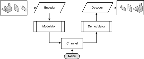
Figure 17.6 Basics of a digital communication system.
Modulator and Demodulator
The modulator transforms the output of the digital encoder into a format suitable for the channel. The demodulator attempts to recover the correct channel symbol in the presence of noise. When the wrong symbol is selected, the decoder tries to correct any errors that result.
Channel
The channel is the medium that transmits or transports the signal. It is where errors are introduced. The medium may be radio, twisted wire pair, coaxial cable, fiber optic cable, magnetic tape, optical discs, or any noisy medium.
Error correction (EC) is used to ensure that the data is proper and completely received at the receiving end of the link. The science of EC is applied to all forms of data, including compressed video, audio, and telephony, and mobile communications.
Forward error correction (FEC), also called channel coding, is accomplished by adding redundancy to the transmitted information using a predetermined algorithm. Such additional bits will add “overhead” to the transmission link but are often essential to making certain that the data can be properly reassembled further downstream in a system. FEC is generally applied when there is no handshaking capability between the source and destination, as in a single (unidirectional) transmission. Serial communication protocols will utilize both scrambling and FEC to aid in the delivery of data over various link formats.
Digital encoding for compressed or uncompressed media will almost always use EC in the processes of encoding. When those signals are carried over unidirectional links (as in a serial transport), the application of FEC is highly likely.
High Availability
When a system is designed with specific protocols and their associated implementations are engineered to ensure a certain degree of operational continuity during a given measurement period, the system may be referred to as a high-availability system. High-availability storage systems provide a high level of service to their users. These systems will be designed to incorporate sufficient system overhead to handle peak periods of demand, that is, when data access to and from the stores is at full throttle, and then more requests are added.
High-availability systems will incorporate varying sets of background tasks that aid in keeping data integrity at its highest level. One of these is a provision that increases the availability of the data by delivering real-time replicas of as many copies as are needed to virtually any location.
High availability may be accomplished by the provisioning of two or more servers: one as a production (source) server and the other a standby (target) server. The same application may be considered for the storage components. Virtualization allows these servers to be configured for several purposes and automatically provisioned to address peak demands or failover modes of operation. This concept keeps these servers active until called upon for a service, mitigating idle time and preserving the investment of the organization.
No matter how much “protection” is put into a system, sometimes it must be taken down. Planned and unplanned downtime definitely impacts accessibility and availability. Many a user on a corporate network has seen the message “it has become necessary to reboot the xyz-server…please save your work and log off immediately.” When this occurs, the access to data becomes zero, the availability of the data or the systems goes to zero, and the productivity of the corporation goes to zero.
Determining the degree of availability requires significant background research that analyzes workflow, data throughput, protection, and a time/value equation that assesses the cost of downtime and many more conditions. Most providers of highend and intelligent storage platforms have the tool sets to help the user understand the cost and performance impacts, at various degrees, of implementing a high-availability system.
High-availability solutions can be physically extended to both local and remote server/storage configurations, used for disaster recovery, or employed globally to geographically isolated locations.
Extensibility
By definition, in the information technology world, extensible describes something that is “designed so that users or developers can expand or add to its capabilities.” A typical well-known programming language example is the Extensible Markup Language (XML), which was designed to be added to by the users through the following of more formalized or accepted approaches versus those found, for example, in HTTP. Lesser examples, such as those used in software applications, are colloquially called “hooks,” that is, a provision or capability for a user that allows a system to be amended or modified to suit a particular feature, application, need, or use.
Storage systems, by nature, must be extensible but not necessarily by the same constructs as in software or programming languages. The addition of storage as disk drives, complete arrays, entire SANs, or NAS attachments should be straightforward and easily accomplished if a storage platform is said to be extensible. The degree of that extensibility is what sets one system apart from another. The level to which you can expand that system is also of key importance, one that would prevent the necessity for a “forklift upgrade” just to gain additional storage or performance.
Videoserver platforms should be extensible. For the most part, the architecture of the codec and server components should be such that as new codecs come to market, they can easily be added to the server system without unduly disrupting the remainder of the server’s functionality and certainly without a forklift upgrade.
Frameworks
Extensible designs are also called frameworks, as they set the boundaries and the targets by which a system performs or grows. However, extensibility, in the previous and following examples, can be as much a marketing term as it is an application of technology.
A framework can be a real or a conceptual structure that is intended to serve as a support or guide for the building of something that expands the structure into something useful.
A framework may be a layered structure indicating what kind of programs (in a computer system) can or should be built. The framework should describe how the structures or programs interrelate. A framework may
•be defined for a set of functions within a system
•describe how those systems interrelate
•be the layers of an operating system
•be the layers of an application subsystem
•represent how communication should be standardized at some level of a network
Computer system frameworks may include the actual program applications, or may specify programming interfaces, and may offer programming tools for using the frameworks. In general, a framework will be more comprehensive than a protocol and more prescriptive than a structure.
Extensible Storage Engine
Searching on the term “extensible” reveals a Microsoft core component formerly known as Joint Engine Technology (JET), often used interchangeably with the term Extensible Storage Engine (ESE), as in “JET Blue” or just simply “JET” (also “JET Red,” a database engine that is used by Microsoft Access). Both JET implementations are completely different with vastly dissimilar feature sets.
Indexed and Sequential Access Method
ESE, a Windows component introduced first in Windows 2000, is an advanced indexed [and] sequential access method (ISAM) storage technology that enables applications to store and retrieve data from tables using indexed or sequential cursor navigation. The ISAM product was originally developed by IBM for mainframe computers and had many related concepts specific to product names. ISAM was introduced as a database system API for search indices, or more commonly as any index for a database, relational or otherwise. The original ISAM product was replaced with a methodology called Virtual Storage Access Method (VSAM), which later became DB2, the primary database management system (ca. 2004). Today, ISAM-like implementations extend to products from MySQL, Paradox, and other database managers.
ESE supports and provides a crash recovery mechanism so that data consistency is maintained even in the event of a system crash. It provides Atomic Consistent Isolated Durable (ACID) transactions over data and schema by way of a “write-ahead log” and a “snapshot isolation model.” ESE transactions are highly concurrent, making it useful for server applications by caching data so as to maximize high-performance access to that data.
Note that ESE is for use in applications that emphasize a need for fast and/or light-structured data storage, where raw file access (or the registry) does not support the application’s indexing or data size requirements. It is used by applications that never store more than 1 Mbyte of data, but it has been used in extreme cases for applications with databases in excess of 1 Tbyte and commonly over 50 Gbytes. Not all these features or APIs are available in all versions of the Windows operating systems.
Atomic Consistent Isolated Durable (ACID)
The changes that occur in a database or transaction-based environment must be processed reliably. Applications for media workflow, such those used in editing, metadata management, and asset management, depend upon multiple levels of interlinked databases. The idea of ACID is a little hard to grasp, unless one puts himself/herself in the actual procedural steps that occur during a database transaction, and then suddenly there is any level or form of departure from that orderly process. Such things occur when there are outside influences such as a momentary power glitch, an unexpected software routine that stalls the completion of the transaction, an interruption in the network connection, or a host of other hiccups that may never even be noticed on the outside.
Databases and transaction processing are essential to operational models in file-based workflows. Metadata and the servers that support that data are essentially relational database systems that hold the keys to the assets in terms of structural and descriptive information. Metadata servers will constantly change, not unlike what occurs in transaction-based processing. Keeping the metadata and the metadata servers aligned requires that a consistent set of procedures and parameters are maintained. This is where the term ACID comes in play.
The acronym ACID means the following:
•Atomic—all changes are made (committed) or none are made (rolled back).
•Consistent—the transaction will not violate declared system integrity constraints and the rules of the database.
•Isolated—the results are independent of the concurrent transactions.
•Durable—any committed changes must survive various classes or levels of hardware failure.
Atomic
The meaning of atomic is that all the changes or none of the changes that occur by a transaction are recorded for posterity. This is the property where clients will see all or nothing is Isolation.
If your application or the database server crashes in the middle of the transaction, then none of your changes will “take.” If the database is volatile, it becomes trivial, but if it is “durable,” then the transaction, that is, all of the changes, will be rolled back; essentially the changes are discarded.
On the outside, this may seem a poor idea; however, it is generally better than committing an unpredictable or incorrect action that is really only a partial product of the production database.
Consistent
All transactions maintain data integrity constraints. When a data set meets integrity constraints, it can be called consistent. A transaction maintains data integrity constraints if, when starting with a consistent data set, the transaction will result in a consistent data set.
A database management system (DBMS) can maintain consistency by aborting transactions that would cause inconsistency. To make this clear, consistency does not require correctness. Consistency with regard to database systems does not refer to the sort of cache consistency issues seen in distributed computation; in this scenario the issues would be handled by what is called “isolation.”
Consistency will not apply to the intermediate stages of a transaction. The transaction must be completed, without interruption, before it can be considered consistent.
Isolation
In database management systems, isolation is a property that defines how or when the changes made by one operation become visible to another concurrent operation. In other words, in successful transactions, the reads and writes of one transaction will not be affected by reads and writes of any other transaction, whether or not those other transactions were or are successful.
Isolated transactions are ordered and considered “serializable,” that is, they occur one after another without deviation. The final state of the system can be reached by placing any of the system transactions in a global order where each transaction occurs one at a time without any concurrency.
It is said that the isolation property is the most often relaxed ACID property in a database management system.
When discussing implementations of transactional systems, one might hear about “optimistic transactions” and “pessimistic transactions.” These two terms describe how isolation is achieved.
In optimistic transactions, the transaction management application generally assumes the other transactions will complete and further assumes they will not read or write to the same place twice. It allows reads and writes to data accessed by other transactions; however, should it turn out that the other transaction is aborted, or that an ordering conflict occurred (such as a transaction actually hitting the same place twice), then both transactions will be aborted and retried. There is the potential for a live lock, which would give no guarantee of progress.
In a pessimistic transaction, resources are effectively locked until they are committed. This guarantees that nothing else can interfere with transaction, yet if one transaction needs the resources in use by another, it will wait, often unnecessarily, which can hurt performance.
If the other transaction needs the resources of the first, then this results in a deadlock. Such a deadlock can be broken by first detecting it and then selectively aborting just that one transaction. This action allows progress to be guaranteed.
Many hybrid approaches to these actions may exist; for example, optimistic at first, less optimistic on retries, with the aim being to achieve the typically greater performance of optimistic transactions while sustaining the ability to guarantee progress from the pessimistic approach.
Relaxing this isolation property generally occurs for the same reasons that those hybrid models vacillate between optimistic and pessimistic: to improve performance and guarantee progress.
The ANSI/ISO SQL standard defines these isolation levels as follows:
•SERIALIZABLE
•REPEATABLE READ
•READ COMMITTED
•READ UNCOMMITTED
Durable
Sometimes viewed as the easiest requirement to meet, what it really means is that a committed change makes a permanent change to the data. Usually, a database client initiates a transaction, performs some operations on data, and then issues a commit.
Until that point occurs, the client should not assume anything about the outcome of the operation, even if the client application allows the user to see some kind of success in each operation.
Once the DBMS responded with an authorization to forward and to commit, the DBMS must make sure that anything that happens to the database once the modifications are issued will persist virtually forever. This does not necessarily mean that the data itself is physically changed (there are reasons for the “undo” command), it provides for an option by another client to modify the change again in the future, insuring the logical effects of modified data on future transactions.
Simply writing modified data to the disk is not enough to achieve durability. It is still possible that the disk may crash (however, there are other means to reduce the likelihood of this and the resultant impact). What happens on the protection side is that the database manager will keep logs about the changes it makes, and will first make sure that the logs are permanent. Usually, these logs need to be redundant, and only after the logs are validated and the software flushes the operating system buffers can the DBMS issue the command to commit the operation, assuming that the remainder of the conditions are properly met.
Despite the intent to follow the properties of ACID, sometimes for either efficiency or speed one may selectively sacrifice certain aspects of ACID.
Extensible Metadata Platform
Another example of extensibility, one that is more relevant to the rich-media world, is the Extensible Metadata Platform (XMP), developed by Adobe. XMP provides users with a common XML framework that standardizes the creation, processing, and interchange of document metadata across publishing workflows. Encompassing framework, schema, XMP packet technology, and an XMP Software Development Kit, XMP is available as an open-source license based on the World Wide Web Consortium’s open standard for metadata, known as the Resource Description Framework (RDF).
The embedded metadata can include any XML schema, providedit is described in RDF syntax.
Resource Description Framework (RDF)
A standard model for data interchange on the Web, RDF has features that facilitate data merging even if the underlying schemas differ. The RDF specification consists of a suite of recommendations from the World Wide Web Consortium (W3C), which were published in 2004.
RDF specifically supports the evolution of schemas over time without requiring all the data consumers to be changed. It extends the linking structure of the Web to use Uniform Resource Identifiers (URIs) to name the relationship between things, as well as the two ends of the link, usually referred to as a “triple.” URI is a string of characters used to identify a name or a resource on the Internet, which enables interaction with representations of the resource over a network using specific protocols. Schemes specifying a concrete syntax and associated protocols define each URI.
Using this simple model, it allows structured and semistructured data to be mixed, exposed, and shared across different applications. The linking structure forms a directed, labeled graph, in which the edges represent the named link between two resources, represented by the graph nodes.
Interoperability
The ability of a set of diverse systems or organizations to work together is the fundamental meaning behind “interoperability,” that is, to interoperate. When initially defined for information technology systems or services, the intent was to make sure that the interfaces employed were thoroughly understood, so that they would work with other systems and products, and that they would endure without restriction to access or implementation for the present and the future. In short, to be interoperable means the product’s interface has no encumbrances to working with other products.
When reflected in a technical systems engineering perspective, a similar definition can be applied.
Open Standards
For a system to be interoperable, it is often referred to as employing “open standards.” An open standard is one that was designed by an open process. They are generally publicly available but may also have various rights-to-use associated with it. Even though it is deemed “open,” there may be various properties relating to how it was designed or how it might be implemented.
The terms “open” and “standard” have a wide range of meanings associated with their usage. There are number of definitions of open standards, which emphasize different aspects of openness, including of the resulting specification, the openness of the drafting process, and the ownership of rights in the standard.
Standards are established documents, recommendations, or practices that are applicable to technologies and are approved by formalized committees recognized as standards developing organizations (SDO). Internationally recognized organizations include the IEC, ANSI, ISO, ITU-T, IETF, and SMPTE. These committees are open to participation by all interested parties and operate on a consensus basis. As noted above, the term “open” may have a wide range of meanings. For example, openness may be the way the drafting process occurred; it may be the ownership rights associated with the adoption of the specification or any combination of many other representations. Industry sanctioned organizations or associations that are specifically focused on certain technologies but are not formal SDOs contribute heavily to the concept of “open” standards development. These independent trade associations have participation (often on a membership/fee basis) from industry manufacturers or technology companies that seek recognition and compatibility in the devices they manufacture, promote, or design.
These trade organizations include the following:
•Storage Networking Industry Association (SNIA)
•Optical Storage Technology Association (OSTA)
•SCSI Trade Association (STA)
•Fibre Channel Industry Association (FCIA)
Best Intentions
Returning to the interoperability topic, most will agree open standards facilitate interoperability and data exchange among different products or services and are intended for widespread adoption. Taking that concept almost literally, if one designs and builds a truly interoperable system, then the exchange of information between those devices should be consistent, openly available, and without restriction.
Of course that is the target intention, but as with most technologies, slight modifications aimed at improving a product’s functionality to make it more marketable or to solve a specifically identified problem leads to standards drift. In file-based media formats, including codec development, companies have sought to find a compromise between a standard and a proprietary implementation. This has led to consternation among how valid or appropriate a particular open standard really is.
It has been the goal of many industry manufacturers to find a means to be fully interoperable yet maintain a performance edge in their products. One such effort is in the establishment of a meaningful and useful interchange of media-centric files (audio, video, data, and metadata) between operating platforms.
Media-Related Interoperability
The Material eXchange Format (MXF), a flexible open file format that was developed during the 1990s by the ProMPEG Forum and standardized by the Society of Motion Picture and Television Engineers (SMPTE), allows for the interchange of file-based media between platforms. MXF is the most commonly recognized wrapper standard in the television industry (next to SMPTE time code). The acceptance by the video industry has helped to promote interoperability between moving media serving platforms.
The MXF standard is not a codec format, but it is an open file format conceived to act as a wrapper of audio-visual content (including associated data and metadata). Designed to promote interoperability, MXF is extensible, which has been demonstrated in the years that have followed since its adoption.
MXF is an extensible format that continues to be developed for many forms of applications and advancements in the moving media industry. The SMPTE standards community has developed many extensions to the standard that integrate with all forms of file-based workflows. The Advanced Media Workflow Association (AMWA) provides the vision to applying the MXF standards as a platform for the industry from which application-specific uses can be uniformly applied to real working situations.
AMWA is developing constrained specifications of MXF to ease interoperability in media workflows. The Application Specifications AS-02 and AS-03, for media versioning and program delivery, meet vital needs for AMWA members and the working industry as a whole.
A detailed look into MXF can be found in Chapter 9.
Science and Technology
Media storage system technologies have followed the paths of IT, data servers, PC workstations, and mainframe computers in developing and adopting the systems necessary for continued success, practicality, and implementation. As a direct result of decades of development, storage system designs have become a science and a technology unto themselves. Although the meanings of the terms may be somewhat different when applied to the technologies they are used in, the concepts remain essentially the same.
Further Readings
Storage and networking trade organizations actively involved in their respective
segments include:
Storage Networking Industry Association (SNIA).
http://www.snia.org/
Optical Storage Technology Association (OSTA).
http://www.osta.org/
SCSI Trade Association (STA).
http://www.scsita.org/
Fibre Channel Industry Association (FCIA).
http://www.fibrechannel.org/
Advanced Media Workflow Association — originally founded in January 2000 as the AAF Association for Advanced Authoring Format, became AMWA in May 2007. It is an open, community-driven forum focused on the creation of timely, innovative, business-driven specifications and technologies for networked media workflows.
http://www.aafassociation.org/
Material eXchange Format (MXF) is a suite of SMPTE standards employed in modern file-based workflows and for the interchange of media related content between devices and systems such as videoservers, compression systems, transcode engines and other electronic AV media engines.
The MXF suite of standards includes:
MXF Base Documents
SMPTE 377M: The MXF File Format Specification (overall master document)
SMPTE EG41: MXF Engineering Guide (guide explaining how to use MXF)
SMPTE EG42: MXF Descriptive Metadata (guide explaining how to use descriptive metadata in MXF)
MXF Operational Patterns
SMPTE 390M: OP-Atom (simple, highly constrained layout for simple MXF files)
SMPTE 378M: OP-1a (layout options for a minimal MXF file)
SMPTE 391M: OP-1b
SMPTE 392M: OP-2a
SMPTE 393M: OP-2b
SMPTE 407M: OP-3a, OP-3b
SMPTE 408M: OP-1c, OP-2c, OP-3c
Generic Containers
SMPTE 379M: Generic Container (how essence is stored in MXF files)
SMPTE 381M: GC-MPEG (Generic Container) (MPEG essence data in MXF using the Generic Container)
SMPTE 383M: GC-DV (Generic Container for DV) (DV essence data in MXF using the Generic Container)
SMPTE 385M: GC-CP (Generic Container for Content Packages) (SDTI-CP essence data in MXF using the Generic Container)
SMPTE 386M: GC-D10 (Generic Container for D10) (SMPTE D10 essence data in MXF using the Generic Container)
SMPTE 387M: GC-D11 (Generic Container for D11) (SMPTE D11 essence data in MXF using the Generic Container)
SMPTE 382M: GC-AESBWF (Generic Container — AES/Broadcast Wave) (AES/ EBU and Broadcast Wave audio essence data in MXF)
SMPTE 384M: GC-UP (Generic Container — Uncompressed Picture) (Uncompressed Picture essence data in MXF using Generic Containers)
SMPTE 388M: GC-AA (Generic Container — A-law Audio) (A-law coded audio essence in MXF using the Generic Container)
SMPTE 389M: Generic Container Reverse Play System Element
SMPTE 394M: System Item Scheme-1 for Generic Container
SMPTE 405M: Elements and Individual Data Items for GC SI Scheme 1
Metadata, Dictionaries, and Registries
SMPTE 380M: DMS1 (Descriptive Metadata 1) (standard set of descriptive metadata for use with MXF files)
SMPTE 436M: MXF Mappings for VBI Lines and Ancillary Data Packets
SMPTE RP210: SMPTE Metadata Dictionary (current version online at http://www.smpte-ra.org/mdd/index.html)
SMPTE RP224: Registry of SMPTE Universal Labels