9
INTERCHANGE, TRANSCODING, AND WRAPPERS
Until the advent of digital technologies and before file-based workflow, the video industry (as NTSC or PAL) had a common denominator by which it exchanged content (i.e., picture and audio essence). The coaxial cable interface, per the SMPTE 170 standard, was the fundamental real-time interface used to move video content between one device and another. Audio would be carried on a separate interface, and the storage medium of choice was a relatively few different video (or audio) tape formats. The analog successor, SDI (SMPTE 259M and SMPTE 292M), further provided for a common, consistent, and standardized transport between devices regardless of how the original essence was stored on the medium where it was generated or transported.
Only as recently as a couple of decades ago, issues of exchanging file-based media were nonexistent. Beginning with the dawn of nonlinear editing, which emerged in the early 1990s, the transport and manipulation of video and audio (essence) would begin a transformation from a real-time nature to a non—real time domain. Early instances of video content for production purposes being stored as files would appear on purpose-built platforms using proprietary codecs that kept individual frames of video on hard drives, and then under software control would play back the string of individual frame files to reproduce the original or modified moving images.
Content interchange, even among similar devices, was very limited. If the content was to be used on a different system, it would generally be “printed” back to videotape in real time from the original nonlinear workstation, then physically moved (“sneaker netted”) to and re-ingested onto the other platform or nonlinear workstation. The interchange of data between devices could only occur if the physical workstation platforms were of the same vintage, version number, and functionality. It would be some time before networking over Ethernet or file-based interchange between these video platforms would become part of any mainstream workflow.
As nonlinear editing, computer-generated imaging (CGI), and effects compositing on computer-based platforms became popular, the issues surrounding the interchange of content on videotape, without degrading its quality, gave rise to a need for what we eventually termed “file-based workflows.” The process, except for a few instances, was relegated to only a few platforms and for the most part, content was only exchanged between similar devices from the same manufacturer. “File interchange,” and the storage of those files onto separate subsystems, was a workflow that did not occur except when those systems were identical, right down to the specific software, codec, and application version.
This chapter discusses the issues and challenges associated with file interchange and workflow, beginning with the introduction of the platforms and moving through the topics of wrappers, transcoding of files, and the various processes of migrating the essence (audio, video, and data) through the working environment now comprised of servers, networks, and compressed video domains.
KEY CHAPTER POINTS
•Real-time, non-real-time, online, and off-line postproduction processes related to content as files
•Vocabularies and terminologies related to working with file-based workflows as applied to transcoding and essence
•Files, platforms, and formats defined as they apply to media-centric operations in a file-based or streaming environment
•Elements of the Media Exchange Format (MXF) standards, including how MXF came to be from the origins of the EBU and the SMPTE Task Force report of the late 1990s
•Description of Patterns, metafiles, containers, and wrappers in their fundamental forms including how they are applied through items and packages
•Conversion and the steps in transcoding as it relates to both baseband and file formats, transrating, and multiplatform conversion and distribution
•Real-time and off-line transcoding, with the three modes of transfer characteristics
Moving Toward Non—Real Time
Early computer-controlled electronic editing of video content was an almost entirely linear-only process that was governed by the lack of any affordable digital formats, nonlinear or randomaccess storage platforms, or software-based architectures. While computerized linear videotape editing (e.g., on the CMX editors) was certainly a serious advancement from the days of film editing, it was a far cry from what we consider “normal” in today’ thinking with the process of timeline-based, nonlinear video and audio editing.
The transition from real-time, linear workflows to non—realtime, random-access file-based workflows evolved over a period of about 50 years. It began with the first videotape recorders (and continued through the demise of regular film-only editing) then progressed through various videotape and nonvideotape platforms. The ramp up started with off-line editing and moved to timeline-based, graphical user interfaces to almost entirely a nonlinear postproduction world.
Off-line Editing
The development of today’ current practices began from the processes referred to as “off-line editing.” Off-line, as it became known, evolved out of the need to control the time spent in the online linear editing suite. By predetermining the EDK using offline systems, the online editing process would then be reserved for the final conforming of a program only. The development of today’ nonlinear editing platform most assuredly dated back to the concepts of off-line editing processes.
Initially, off-line editing was performed on less expensive ½-in. VHS or Umatic ¾-in. tape decks where the original material was first copied to this format with a burned-in “window-boxed” image of the time code that would allow the human editor to reference the precise frame of the video segment they would be “clipping” and joining to subsequent clips during the creation of the edit decision list or EDL. The process was usually a cut-only assembly of the sequences, with annotations for transitions, effects, or titling being added externally during the decision process. These off-line tools allowed editors to make decisions, that is, create their EDLs, which would later be used in the online postproduction environment.
The same computer-driven electronic controllers that were used in the online production suite would be utilized in the offline process but would be connected to these less-expensive transports. The off-line version was frequently used as an approval process but seldom would the off-line version be used as a final production release. This workflow would later be transformed to an electronic tapeless editing process that became the roots of what would be called nonlinear editing (NLE)—a method of rapidly creating the EDL without the intent of delivering a final product from that platform.
Computerized Editing
Early computer-based NLE systems were used in much the same fashion as their tape-based editing system counterparts. The workflow began with an initial step of ingesting each segment of content from a master videotape into the NLE platform, where it was recorded to disk. Since the images to be used in generating the EDL did not need to be of high quality, the earliest NLEs used a format that produced a marginal- to mid-quality reproduction of the video and audio segments. The resultant deliverables from the NLE were a numerical EDL and a “rough-cut” audio and video version of the completed program.
The EDL data would be output to a floppy diskette, which would then be imported to the online computer editing system. The video and audio rough cut could be played out and recorded to a ¾- or ½-in. tape that would be used as a reference for the online edit session. Sometimes the workflow included transferring, in real time, and recording rough-cut content to a crystal master videotape. During the online edit session, the final “conformed cut” would be insert-edited over the top of the rough-cut version already on the master tape, replacing the rough version with a final version of high quality that precisely matched the rough-cut version.
Early NLE implementations might not have employed editing on a graphic display, trick-effect previews, scrub audio, dissolves, keys, or effects—let alone any kind of video simulation of the edit directly to a computer screen. However, it was not long before companies, such as Avid Technology, would pioneer a new concept called “timeline editing” that would cause a paradigm shift in the workflows of first off-line and eventually online editing on a computerized workstation.
Compressed Video
Video compression technologies would become a key component to the development of on-screen visual, electronic nonlinear editing (NLE) workflow. Of the relatively few NLE platforms that were available in the early years, most employed their own proprietary codec that captured each linear frame of video and saved them as a linked string of individual files that when played back produced a reasonable representation of the original images. Again, quality at first was not the motivational force behind the NLE, as a rough version of what the final segments would look like was submitted and then a conformed cut was created in the linear online edit suite.
These NLEs used the JPEG tool kit and tailored it to the architecture of the software-based editing platform. Even though the tool kits used standard JPEG compression properties, the motion-JPEG implementations were nearly always unique to the NLE, by platform, version, and audio/visual “reference” level. This forced the user to buy one or more NLE workstations, all usually configured with proprietary I/O cards, disk drives, and controllers; and software licenses coupled with maintenance or support contracts that ensured the user would remain “locked” into that vendor’ system.
All of the activity remained the same for awhile, with the concept of “file-based workflows” still a decade or more away from reality back during this time. Analog video and audio interchange, thus, remained locked to videotape, retaining it as the only true interface between one system and another. Serial digital I/O was unnecessary at the time, yet within a few years of implementation, as compression improved and codec card sets with SDI I/O emerged, we began to see a demand for a completely digital video version, promoted by the advances in codec quality, real-time processing, rendering of dissolves, etc.
Issues with Interchange
The professional audio and video production industry, such as the computer industry, has adapted to the requirements of translating and changing from one platform to another or from one software product to another, for quite some time. For the video and audio industry, the interchange of files between vendor-specific platforms or between standardized or nonstandardized video or audio compression formats occurs through a process called transcoding.
As the professional industry (i.e., broadcast and postproduction) began to accept the notion of digital video, attempts to address the issues associated with interchanging material content, at a file level, between one platform and another gradually paved the way to an infant form of file standardization. Once this foundation was cast, a basis for file-based interchange was enabled and the dependency on real-time, linear transport, and videotape storage began its asymptotic slope toward extinction.
Incompatibilities
Today, video and audio content is used in more ways and on more devices than was ever anticipated during the emergence of nonlinear editing and disk-based storage. In similar fashion, content is captured, produced, and then released for consumption using a plethora of platforms, technologies, and distribution methodologies, which strive to find a common means for interchange.
Unfortunately, the growth of incompatible and competing formats for production and delivery, including broadcast, creates a set of issues that has to be resolved each time a new encoding concept is envisioned or introduced. It goes without saying that no single format can provide all that people require, but that has not stopped the progression of new and improved encoding technologies aimed at addressing both the user’ needs and the growing technical issues associated with the digital video era. Continuing the evolution of systems demanded a solution that would provide a suitable means for interchange that could serve as many users, formats, and resources as possible.
The solution is called transcoding and is defined as the process of converting or translating one format of media to another. The process facilitates the requirements necessary for moving video, audio, and associated other data media through the workflows surrounding production, postproduction, replication, archive, and delivery.
Media File Vocabularies and Terminologies
To place the processes of handling media files into perspective, some fundamental terminologies must be established. The industry has prescribed different sets of terminologies that are used in describing the elements that make up files and their associated ancillary elements. Some of these are recognized nomenclatures, others share similar names, and still others use alternative names interchangeably. Often, these nomenclatures convey differing and sometimes incorrect meanings.
File Format Clarification
File formats should not be confused with file systems or operating systems, which are discussed in “Files and Operating Systems” (available on the companion website). File formats are prescribed structures that are created from media that is usually compressed from full-bandwidth audio and video streams during the capture or ingest process. Files are then stored on magnetic, solid state, or optical media or are used in the transmission process between different locations on a network-based topology.
In our ever evolving multimedia, audio and video world we have developed literally shopping carts full of file formats. The variety of files, formats, and media structures creates hardship when trying to assess a consistent vocabulary for describing these files and formats. An even greater issue is raised when dealing with the challenges of interoperability between the makers of equipment that must process and transform these files for use on their systems and for distribution or delivery to and from varying platforms.
For consistency purposes, we would like set parameters and descriptions that are recognized by the industry and a reasonable degree of conformity at a standards level. Throughout this book, that is, not only when discussing the conversion and transcoding processes but also when examining workflow and storage system properties associated with file-based media, we will utilize those terms that are established by recognized standards organizations, such as the Society of Motion Picture and Television Engineers (SMPTE) and the International Telecommunication Union (ITU). When terms have been adopted without a standards body recommendation, perhaps as a de facto representation, those will be identified accordingly.
Platforms and Systems
At the most basic level, a platform is the fundamental technology of a system’ (e.g., a computer’) hardware and software, which defines how a system is operated and determines what other kinds of services (e.g., software) can be used. Thus, when looking at how this applies to a workflow built around files, the components that make up the various elements that touch and interact with the workflow can be thought of as the platform.
A moving media file, which might contain video, audio, data, and metadata, is the fundamental element that carries the appropriate sets of bits that when properly interpreted by the system components will produce the visual, aural, and other information including the “bits about those bits” when sent to those components. In order for this set of bits to be properly interpreted by other platforms, certain rules need to be followed and the formats of those bits must be correctly understood by the other platform or platforms.
In a video recording and playback system, the basic technology of the system’ hardware and software must be constructed such that it defines how the video and audio are encoded and it must also determine what other kinds of video and audio can be presented to the system for playback. The hardware component definitions might include the size and proportions of the video, the screen size that the video will be presented on, the processing capabilities of the encoder or decoder components, and much more relative information all aimed at describing the relationship of the video data to the system. Each of these elements will have limitations that govern what types of video, audio, data, or metadata can be interpreted. If there is insufficient processing capability, then there will be limitations on what size or dimensions of video can be produced, such as standard definition versus high definition.
The hardware in these systems will be used for specific purposes. It might be an embedded system for mobile applications or it might be highly agile to handle multiple tasks simultaneously, such as in a videoserver with ingest (record), playback (output), and file-transfer capabilities.
In addition, in a system, there will be software that has been designed to address the specific limitations and performance capabilities of the hardware. In essence, the software should match the hardware’ design purpose or it will not produce the expected set of results. Hardware and software considerations must also take into account factors such as power, bandwidth, user quality of experience, and other parameters that define the uses and applications for each.
One of the primary reasons why we see so many formats emerging in the video and audio industry is that new platforms are continually developed that make improvements in the quality of experience that the user needs, wants, or hopes to achieve. The result is that new video and audio encoding technologies are produced, which intend to answer the needs or wants of the user. In turn, we find that new formats, created by new encoding methods, produce new platforms on a cyclic nature defined by users, video equipment manufacturers, or combinations of both. Whether a format, platform, or product survives depends on its acceptance by the community who buys or uses these emerging and evolving technologies, for most any reason.
These new platforms are faced with the daunting task of either complying with all the previous legacy formats or ignoring them, and hoping their new platforms will be more profitable and successful than the legacy predecessors. The end result is that for users to enjoy the new added value of this new platform requires that another external element be able to translate or adapt the file so that it can be presented to the new platform, thus making the new platform extensible to users who might need to use it for more than a single dedicated application.
Compressor—Decompressor
A fundamental element that handles the major elements of video (or audio) compression is the codec. By definition, at the simplest level as it applies to the moving media technology space, a codec is the hardware, or software, engine that moves frames of video or audio from the uncompressed domain to the compressed domain (a compressor) or vice versa (a decompressor). Both elements are required in an end-to-end solution that takes video and audio content in real time into a system and stores it for later release (output) as video and audio, once again.
Let’ state that again, this time referring to the diagram inFigure 9.1. Video and audio are presented to the input of a device on a physical connector, usually a BNC connector. If the video and audio are carried as a stream in the standard video formats per SMPTE 259M (SD) or 292M (HD) transport (as embedded audio in the serial digital interface, SDI) domain, then the digital stream is considered video “full bandwidth” with a data rate of 270 Mbits/second for SD (SMPTE 259M) or 1.485 Gbits/second for HD (SMPTE 292M).
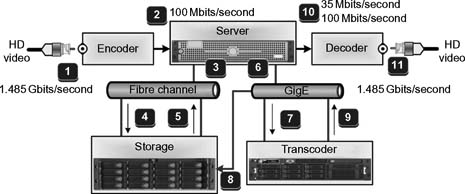
Ingest
(1) Baseband 1.485 Gbit/second HD digital video is input to Encoder through (2). The Encoder creates 100 Mbit/second DVCPRO HD compressed files that are transported through path (3) from the server on Fibre Channel over path (4) to storage.
Transcode
DVCPRO HD 100 Mbit/second files called from storage (5) to server (3), buffered and moved through (6) on GigE network through (7) to transcode engine; files are transcoded to 35 Mbit/second MPEG-2, then through the server they move back into storage through path (9→8).
Playback
Files playback from storage on path (5→3) to server; then through path (10) to decoder. Software codecs in the decoder allow native 100 Mbit/second DVCPRO HD or transcoded 35 Mbit/second MPEG-2 files that are decoded to baseband HD as 1.485 Gbit/second SMPTE 292M high-definition video (11).
Figure 9.1 Functional diagram of the I/O, encoder, server, storage, transcode engine, decoder, and network interface (Fibre Channel and G igabit Ethernet) for a typical videoserver system.
There are a lot of data to store, and in 90% of the applications that employ file-based workflows, the higher raw bit rates are seldom employed. So, the full-bandwidth data is presented to an encoder that compresses the video and audio into a format—hopefully an open standardized format, and deposits those elements, as a file, to storage.
Figure 9.1 shows elements of a digital video system signal flow: video encode, transcode, storage, and decoder for playback. The signal flow is hypothetical as there are many alternative configurations possible.
The encoder, usually one half of a codec pair, changes that bit stream into a compressed format that is selected from a plethora of available industry accepted formats. The instrument that changes this bit stream from a linear real-time format to a file may be either a hardware-based codec or a software-based codec. Many professional videoserver platforms developed since the mid-1990s have employed hardware-based codecs, but the trend in the past 5 years or so has moved away from hardware-based codecs with embedded software applications that do the compression to a world of software-based codecs. The later, softwarebased codecs have both advantages and disadvantages, which are arguably marketplace-based advantages depending on the vendor or codec software licensee who promotes the implementation. The flexibility of a software-based system is that as technology is improved, the systems are not as easily painted into a corner they can’t escape from. Software codecs can be upgraded without necessarily replacing the hardware underneath them.
Profile and Level
To properly describe and address compression formats, there are two principle terms—profile and level—that are necessary in order to describe the parameters and performance of the particular functionality of the codec. For example, in the MPEG standards, a “profile” defines the specifics of color space resolution and scalability of the bit stream. A “level” describes a specified set of constraints that indicate a degree of required decoder performance for a given profile.
A level of support within a profile will specify the maximum picture resolution, frame rate and size, and bit rate that a decoder may be capable of using. A decoder conforming to a given level is required to be capable of decoding all bit streams that are encoded for that level and for all lower levels.
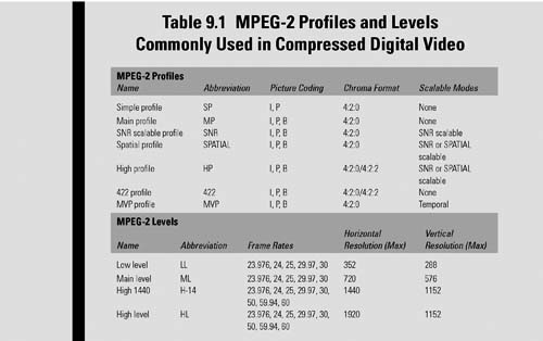
Of the two more familiar compression formats, MPEG-2 and MPEG-4, used for moving image applications in professional environments, there are several sets of profiles and levels. For MPEG-2, some examples include the following:
•MPEG-2 MP@ML, read as “Main Profile” at “Main Level,” describes a standard definition video signal with a maximum bit rate of 15 Mbits/second.
•MPEG-2 MP@HL, read as “Main Profile at High Level,” describes a high-definition video signal with a maximum bit rate of 80 Mbits/second (Table 9.1).
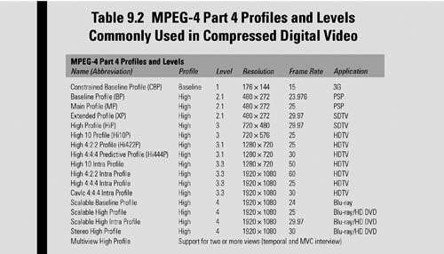
For H.264, a derivative of the MPEG-4 Part 10 (or AVC) standard for compression, there are 17 defined sets of capabilities (i.e., Profiles) that are used to target specific classes of applications. Examples of Profiles for nonscalable 2D video applications include the following:
•Constrained Baseline Profile (CBP)—primarily used for lowcost applications such as videoconferencing or mobile.
•Baseline Profile (BP)—used for applications supported in CBP, plus additional features, but still requires only a limited degree of computing power for the decode process.
•High Profile (HiP)—a primary profile used particularly for high-definition disc storage applications, such as Blu-ray and the DVB HDTV broadcast service.
•High 4:2:2 Profile (Hi422P)—for professional applications with 4:2:2 chroma subsampling that is built on top of the High 10 Profile (Hi10P), which supports 10 bits per sample of picture decoding (Table 9.2).
MPEG-4 Visual (Part 2 of ISO/IEC 14496 “Coding of Audio-Visual Objects”) covers a very wide range of functionalities and types of data, which includes the following:
•Static textures—as in still images
•Moving video—rectangular frames
• Video objects—shapes of an arbitrary nature in regions of moving video
•2D and 3D mesh objects—shapeable, deformable objects
•Animated human faces and bodies
Metafile
A metafile describes how essence, data, and metadata are stored, but the metafile does not describe how that information is coded. In the context of audio and video, a metafile would also be known as a container. In computer data systems, metafile is a term that is generically used to mean a file format that stores multiple types of data.
Graphics Metafiles
For graphics, metafiles would commonly include the following file formats:
•PICT—originally used on Apple’ Macintosh computers as a standard metafile format.
•CGM—defined by ISO/IEC 8632, and known as Computer Graphics Metafile, an open international standard file format for two dimensional (2D) vector graphics, raster graphics, and text.
•EPG—Encapsulated PostScript is a standard format for importing and exporting PostScript language files among applications in a variety of heterogeneous environments. The format is based on and conforms to the Document Structuring Conventions (DSC) detailed in the PostScript Document Structuring Conventions Specification.
•PDF—Portable Document Format is an open standard for document exchange, created in 1993 by Adobe Systems that is used for representing two-dimensional documents (and more latterly 3D) in a manner independent of the application software, hardware, and operating system.
•SVG—Scalable Vector Graphics is a family of specifications of an XML-based file format for describing both static and dynamic 2D vector graphics.
•RTF—Rich Text Format file is a proprietary document file format developed by Microsoft Corporation (1987) that supports Microsoft products and cross-platform document interchange. The current version V 1.1.9–2008 uses XML markup, custom XML tags, SmartTags, and Math elements that follows the Office Open XML (OOXML) specification of ECMA-376, Part 4.
•WMF—In the Windows operating system, the complete term is Windows Metafile (WMF); this is also known as the Enhanced Metafile (EMF).
Generic Metafile
In a more general perspective, the metafile program is enabled to identify and open a container file but might not be able to decode the data contained in that file. Such a program would have lacked the required decoding algorithm, or it could be that the metadata did not provide sufficient information to point to the decoding algorithm. It could also be that there was more than one decoder required: one for audio, one for video, and one that interprets the data inside the container.
By definition, a container format could enfold any type or form of data; however, most of the container formats are specialized for specific data requirements, for example, those that will be discussed in the following contexts of moving media technologies, especially those that are associated with audio and video.
Container or Wrapper
When either of these terms is used in the context of moving media, “container” or “wrapper” is a specialized metafile that describes the grouping of or the set of multiple types of audio, video, data, and metadata, which are associated together as a complete “package” that is delivered to a platform. Examples of wrappers (or containers) include the following:
•QuickTime—developed by Apple, a proprietary multimedia framework that handles video, picture, sound, images, and interactivity
•AVI—Audio Video Interleave or Audio Video Interleaved, part of the video for Windows technology
•ASF—Microsoft’ proprietary digital audio/digital video container format called Advanced Systems Format; formerly, yet still known as Advanced Streaming Format or Active Streaming Format (ASF is part of the Windows Media framework)
•MXF—The SMPTE wrapper standard most commonly associated with media files
•M2TS and M2PS—MPEG-2 transport streams (TS) or program streams (PS) that carry the MPEG-2 essence and associated data
•VOB—data in a container called a video object, which is associated with video for DVD videos
•LXF—a proprietary container form for the Leitch/Nexio videoserver platform from Harris Broadcast
•GXF—a SMPTE standard (SMPTE 360M) wrapper format developed for the Tektronix/Grass Valley videoserver platform; the first standardized wrapper format; set the tone for what would later be the Material eXchange Format (MXF).
• 3GPP (and 3GPP2)—the 3rd Generation Partnership Project, standards for the creation, delivery, and playback of multimedia over third generation (3G), high-speed wireless networks
The industry has already accepted the notion there will never be a universal file format that would suit all applications in all instances. However, the industry has made great strides in addressing interoperability through the establishment of a universal and standardized professional wrapper format. The wrapper acts like a covering or a bottle that protects its contents from disruption or contamination as those elements are transported (carried) between one place and another.
Wrappers serve two purposes mainly: to gather program material and related information and identify those pieces of information. A wrapper does not add much value but is invaluable in providing a unified way to structure content and to access it.
In the early days of file formats for moving images (audio and video), and prior to the standardization of a wrapper format for moving material, there were some wrapper formats that had already been in use. None of these were widely accepted, or they did not provide sufficient capability in terms of openness, extensibility, performance, etc. The movement to develop a set of wrappers was started to coalesce the requirements and ideas and to prepare a standardization process, which ultimately became the Material eXchange Format (MXF).
Generic Wrapper
A generic wrapper is at the highest level of the food chain, and when associated with media applications, it is categorized between streaming wrappers and storage wrappers.
Streaming Wrappers
Streaming wrappers, when applied through a streaming mechanism, provide the container for moving content over IP, Fibre Channel, and other transports.
Storage Wrappers
Storage wrappers, when applied through a mechanism for storage, allow content to be stored in raw form into specialized storage platforms or on a recognized file system such as NTFS or CIFS.
Format
A particular set of codecs (i.e., encoder and/or decoder sets) and a set of containers (or wrappers) collectively make up a “format.” The format may be either platform agnostic (i.e., platform independent) or platform dependent (i.e., platform specific), that is, it must be played back on a platform that is compliant with the format and compatible with the format’ applications.
A cross-platform and platform-specific format is one that is compatible with a varietal set of operating systems but is principally intended for playback on a given family of players.
One should not associate a compression format with a wrapper format. Wrappers are not necessarily affected by the contents of the wrapper and are for the most part agnostic to things such as essence, compression formats, line structures, ancillary data, and so on. The wrapper, whether for media applications or simply other collections of data, is best thought of as a specification for a container that describes how essence (data) and metadata are stored and not how they are coded.
An application (or program) that is able to identify and/or open a wrapped container file would not necessarily be able to decode the contents of that container file. The decoding activity is generally provided by another application in either hardware or software.
Files and Streams
To appreciate the differences between file and stream transfers, let’ look at the major characteristics of each.
File Transfers
In a network, a file transfer is a packet-based data movement over a reliable interconnect that is usually acknowledged by the receiver, which is then heard by the transmitter. The file transfer may be accomplished using removable media (disc, USB drive, etc.). The transfer is initiated with a known start and usually a known end point. It may be a point-to-point or point- to-multipoint, with limitations, transfer. The file formats are often structured to allow essence data to be widely distributed or random byte positions. The transfers are not normally synchronized to an external clock.
Stream Transfers
System transfers are implemented as a point-to-multipoint or broadcast transfer that is open ended with no predetermined start or end point. The interconnect is over a data- streaming interface that is usually unacknowledged. The formats for streaming are usually structured to allow access to essence data at a sequential byte position using a streaming decoder.
Content
The fundamental base element in a file structure for moving or multimedia applications consists of individual sets of raw audio, video, and data, which are referred to as “essence.” Audio generally will consist of individual or paired tracks of sound, including video description tracks or narrative scratch notations. Video could be moving pictures or static images such as graphics or full-screen stills, in resolutions from QCIF through high definition or beyond. Data is information such as time code, closed caption data, descriptions for open captions, etc., but is not considered metadata related to the structures of the files.
When these sets of essence elements are combined with the metadata associated with that essence, they form “content.” To aid in the movement of packages of content, as files, throughout a system with some level of association, content is enveloped or surrounded by a “wrapper,” which is also known in the industry as a “container.” Both terms are confusing and used with much flexibility. Wrappers or containers are often referenced in describing file formats, file extensions, and other descriptors (for example, in the context of a file type as in “.MOV wrapped,” from the Apple QuickTime Movie perspective, or as in “MXF wrapped,” from the SMPTE MXF standards set).
Material eXchange Format (MXF)
One of the more recognized example references for mediacentric file interchange structures is described in the Media eXchange Format (MXF) work efforts of SMPTE. This suite of standards, engineering guidelines, and practices outline, describe, and frame up the methodologies widely used as a foundation for interchange of content as files for multimedia (i.e., audio/video) applications. The specification allows users to take advantage of non—real-time transfers that combine essence and metadata so that it may efficiently be interchanged between servers, storage systems, and businesses.
MXF is a complicated set of SMPTE standards documents that need not be thoroughly understood by many in order for MXF to be effectively implemented. The compliance issues surrounding MXF have been massaged, contorted, and distorted by the confusion among the users, manufacturers, and general community since the adoption of the first specifications in the late 1990s. The following sections of this chapter are meant to skim the toplevel descriptions and components that make up the MXF file specifications and frameworks. This section hopefully provides users with a fundamental idea of the terms and top-level requirements for MXF compliance.
Raw Materials
When referring to multimedia (audio/video) applications, the term essence is described by the SMPTE 377-1-2009 standards document for MXF as the fundamental “raw video, audio, and data streams.” By including the word “raw,” essence is described at its basic state without additives that mention such modifiers as high definition or standard definition (video), analog or AES (audio), and time code or closed captioning (data). While this term is described by MXF, the essence may optionally be contained in an MXF file itself.
An essence container describes that part of an MXF file that carries one or more essence streams. The container may optionally carry metadata that is closely associated with the essence streams. The essence container consists of a stream of bytes that are identified by a unique Stream ID value. Within the scope of a single MXF file, this particular example for the Stream ID is a 32-bit integer that uniquely defines a data stream within that container.
Some formats may include multiple containers. The same compression format (e.g., MPEG-2) may be found in a transport stream (TS) container such as when video, audio, and data are used for broadcast or satellite distribution. The same MPEG-2 may be placed into a program stream (PS) container for storage or delivery, such as in a DVD. Similar scenarios can be applied to codecs such as MPEG-4 Part 2, H.264/AVC or MPEG-4 Part 10, or H.263, which is used as a low-bit-rate codec in older videoconferencing systems.
Task Force for MXF
The origins of MXF can be traced back to the mid-1990s. At that time, the convergence between the IT and the television industries was being taken for granted. Networking, video compression, and video capable storage were in their infancies, with each collectively paving the way to a paradigm shift in production, transmission, and distribution of content. As nonlinear editing was becoming commonplace and videoservers were beginning to be accepted as a reliable replacement for VTRs, the problems with interchange of files between systems and on diverse platforms needed to be addressed.
Impromptu solutions for interchange were being developed and promoted by manufacturers with only a minute amount of standardization backing. This, sadly, resulted in myriad incompatible file formats, ad hoc workflows, and differing terminologies. Where SDI had established itself as a reliable, interoperable link, a completely different scenario was developed, which had little correlation to tape-based workflows or real-time streaming media interchange.
The European Broadcasting Union (EBU) and SMPTE joined forces to produce a blueprint for the implementation of new technologies, which was to look forward a decade or more. The task force produced a pair of documents: a report on user requirements and a detailed collection of the analyses and results obtained from the task force study.
The complete work, published in July 1998, is called the “Task Force for Harmonized Standards for the Exchange of Programme Material as Bitstreams.” The work had a major impact on the industry, with the most important disclosure stating the awareness of an obvious need to perform formal standardization work on “wrappers and metadata.” Ultimately, metadata was placed on a par with audio and video, with the establishment of a standard wrapper becoming a fundamental component in file-based media interoperability and interchange.
Structure of a Basic MXF File
The fundamental MXF file begins with a File Header, followed by a File Body, and ends with a File Footer. The data structure of the MXF file includes a full definition of the File Header and File Footer. A number of associated documents are required to provide the full specification of an MXF file.
File Header
A File Header must be present at the start of every MXF file. It shall include the Header Partition Pack and the Header Metadata as shown in Figure 9.2; and may also include a Run-In and an optional index table, as shown in Figure 9.3.
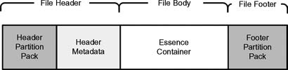
Figure 9.2 Overall data structure of a simple MXF file.
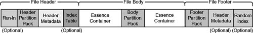
Figure 9.3 Overall data structure of an MXF file with optional components.
File Body
This middle section provides the mechanism for embedding essence data within MXF files and shall contain zero or more essence containers. When there is more than one essence container in the File Body, the essence containers shall be multiplexed together using Partitions.
For an Essence Element, there shall be an associated MXF essence container specification defining how the Essence Element shall be “key-length-value” (KLV) encoded in the essence container, how the Index Table specification shall be applied for indexing the Essence Element, and how to identify the Essence Descriptors that are required to describe the Essence Element.
MXF Metadata
The standard allow for MXF metadata-only files. These files may have no File Body and hence no essence containers.
File Footer
The File Footer is located at the end of the file, and shall include a Footer Partition Pack. The File Footer may also include a repetition of the Header Metadata and a Random Index Pack and may include one or more optional Index Table segments.
The File Footer must be present unless there is a Specialized Operational Pattern used, which defines the footer to be absent or optional, and if so, there are other mechanisms that shall be used to identify that the status of the file is complete and that it is closed.
Partitions
Each MXF file is divided into a number of Partitions that logically divide the file to allow easier parsing, to aid in streaming, and to manage the creation of Index Tables, which ease random access into a storage system. An MXF file may contain zero or many different essence containers and Partitions, which help to manage them. Partitions shall consist of and be ordered as follows:
•one Header Position (at the front)
•zero or more Body Partitions (or Partitions of other types) in the middle
•zero or one Footer Position (which must follow the last of the Body Partitions)
An open Partition is the one in which the required Header Metadata values have not been finalized, that is, the required values may be incorrect. A closed Partition is the one that has a Partition Pack where all the values have been finalized and are correct, and either contain (a) no Header Metadata or (b) all the proper Header Metadata with required values that are finalized.
Operational Patterns
This portion of the standard defines the specific details of every component in an MXF file together with the framework needed to define the relationships between the components. The MXF-OP structures specify the levels of file complexity. The MXF standards intend that Operational Patterns (OP) be written and standardized as separate documents, giving rise to a dynamic set of documents that can be appended without having to reballot the entire MXF set of standards each time a new OP or another portion is added.
The Operational Pattern of a file is identified via a Universal Label (UL) value in properties that are stored in the Preface and in the Partition Packs.
In the Operational Pattern definitions, there may be constraints placed on the capabilities of the File Body. Most Operational Patterns will be written as a constraint on the axes, either in the item complexity or in the package complexity. These are referred to as Generalized Operational Patterns. Regardless of the Operational Pattern, any MXF decoder should be able to read the Partition Pack of the File Header and include the ability to skip over any Run-In bytes. Any MXF decoder should be able to report the contents of the file. It should report if the file is beyond the decoder’ capabilities and why it cannot process the file.
A metadata-only file of an Operational Pattern may be created, which has no essence containers and shall correctly report the complexity of their timeline per the mechanisms defined in the MXF Operational Pattern identification structures and labels.
The most commonly used Operational Patterns are the General Operational Pattern OP1a and the Specialized Operational Pattern OP-Atom.
Specialized Operational Pattern Atom
“OP-Atom,” defined in SMPTE 390M-2004, is a specialized Operational Pattern for the storage and exchange of an MXF file with a tightly defined structure. OP-Atom is designated for a single item of essence described by a single essence track. The standard defines the operating restrictions, structural metadata objects, and individual attributes, which shall be applied to the MXF file-format specification to achieve interoperability when exchanging a single item of audiovisual material. It is a simple, predictable, layout with minimum scope for variation, specifically intended for applications where each essence track is held separately.
Some applications may find that OP-Atom’ provisions are unsuitable, in which case a Generalized Operational Pattern or a different Specialized Operational Pattern should be used. Regardless of the chosen OP, the suitability of a particular pattern needs to be judged on a per-application basis.
With regard to OP-Atom, some specific areas to consider are as follows:
•Optimization where the record (file creation) process is completed before a playout (file read) process is started. This may make OP-Atom unsuitable for concurrent applications, such as when the record/playout (file creation/file reading) processes happen at the same time.
•OP-Atom places a full index table in the footer. When the encoding uses variable bit rate (VBR) essence, this may make it impossible to use the file as a streaming format, especially where stream delivery requires an advanced knowledge of the frame boundaries. In addition, with VBR essence, a possibly very large index table would need to be stored separately until the file recording ends.
•OP-Atom files only hold a single track of essence data. Where applications need an external mechanism to synchronize essence among multiple files, this standard does not define such a synchronization method. However, OP-Atom does include an annex detailing a method of informatively recording synchronization among files created as a group.
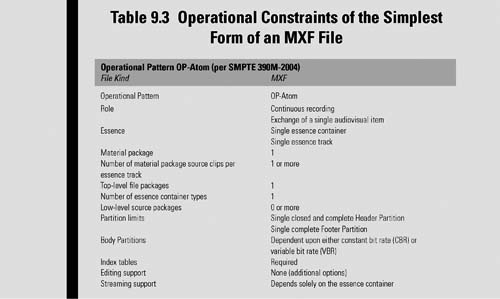
The general constraints for OP-Atom in MXF include the items in Table 9.3; note that the Body Partition constraints refer to additional details found in Section 8 of the SMPTE standard and relate to whether the compression is constant bit rate (CBR) or VBR.
For OP-Atom files with CBR index tables, the constraints for these Partitions are to be followed:
•Header Partition—including closed and complete Header Metadata and an optional index table, no essence container data
•Footer Partition—including a repeat of the index table, no Header Metadata
For OP-Atom files with VBR index tables, the constraints for these Partitions are to be followed:
•Header Partition—including closed and complete header and an optional “sparse” index table, no essence container data
•Body Partition—including the complete essence container
•Footer Partition—including the complete index table, no Header Metadata
Items and Packages
Figure 9.4 shows the Generalized Operational Patterns described on two axes—the horizontal “Item Complexity” axis, and the vertical “Package Complexity” axis—according to the complexity of the items (playlists or edit lists) and the packages (single, ganged, or alternatives). Operational Pattern qualifiers define file parameters that are common to all Operational Patterns.

Figure 9.4 Generalized Operational Pattern (OP) complexities or “structures” are described in the horizontal (Item Complexity) and vertical (Package Complexity) axes.
The Material Package (MP) is a subclass of the Generic Package with a number defined by an Operation Pattern specification. The tracks of the Material Package shall define the “output timeline” of the file when played. There are constrains, which are detailed in the MXF documents, pertaining to the MP. For example, there can only be one time code component in a time code track of an MP. Furthermore, the number of Picture Tracks, Sound Tracks, and Data Tracks are controlled by the OP specification and by the Top- Level Source Package(s), which are associated with the Material Package.
The Source Package, Top-Level File Packages (which consist of the Source Packages), and the references to a descriptor that describes the essence are subclasses of the Generic Package. In addition, there are Lower Level Source Packages that document the derivation or history of the source clips of the source essence.
Item Complexity
This axis describes that there is more than one File Package (FP) and how on the timeline they are arranged according to the following:
Single Item—when only one item is contained in a file; it will consist of a single MP, or Material Package Source Clip, that will be the same duration as the FP or Top-Level File Package(s).
Playlist Items—when several items are butted against each other; each MP is the same duration as an entire FP.
Edit Items—when the file contains several items with one or more edits; any MP may come from any part of any appropriate FP.
Package Complexity
A Package is the name used for all subclasses of the Generic Package, and in the MXF Operational Pattern axes, is layered (and designated by an alpha character) according to the following:
Single Package—the MP (Material Package) can only access a single FP (Top-Level File Package) at a time.
Ganged Packages—the MP can access one or more FP at a time.
Alternate Packages—when there are two or more alternative MPs each of which can access one or more FP at a time. These Alternate Packages may comprise either single packages and/ or ganged packages.
Essence Container
The essence container standards provide those specifications for the Picture, Sound, and Data essence containers that are in a File Body. The File Body can contain one or more essence containers. Various other associated MXF essence container specifications describe how these different essence components are placed in the MXF file.
Each essence container specification must meet the needs of program interchange, with each essence container specification written as a stand-alone document or document set that in turn must meet the requirements set out within the master SMPTE MXF document (S377-1-2009c) in order for it to be accepted as a compliant MXF essence container.
All essence and metadata types can be constant data rate or variable data rate.
Descriptive Metadata
Descriptive Metadata standards define optional editorial metadata that enhances the usability of the essence content of an MXF file.
SMPTE Universal Labels
MXF Files include SMPTE Universal Labels (ULs) in the File Header that provide for an early identification of the Operational Pattern (OP), of the existence of Descriptive Metadata plug-ins, and of the essence containers in the File Body.
Dark Metadata
Metadata values that are inserted into a file, which are unknown to a decoder, are called dark metadata. This metadata may be privately defined and generated. The metadata may include new properties that were added to the set, or it may be standard MXF metadata not relevant to the application processing the referenced MXF file.
Rules are set in the MXF standard regarding the use of dark metadata so as to prevent numerical or namespace clashes when private metadata is added to a file already containing dark metadata.
MXF Extensibility
The structures, Operational Patterns, implementations of various coding formats, and the KLV coding structure of MXF consist of several documents. More is added to MXF all the time through the work of the SMPTE Standards Community, along with the manufacturers of codecs, image capturing systems, and servers. Figure 9.5 shows the relationships and divisions of the MXF documents suite for users with access to the SMPTE standards or for searching on the website for more details.

Figure 9.5 Architectural diagram of the MXF suite of standards and implementation plug-ins.
The extensibility architecture of the SMPTE MXF set of standards has the core SMPTE MXF document (S377M) and the associated essence sets on the left, the Descriptive Metadata Scheme (DMS) plug-ins on the right, and the Operational Patterns on the top. The data encoding protocol, in terms of KLV is described in SMPTE 336M.
Conversion and Transcoding
We begin the second part of this chapter focusing on the conversion of, and the transcoding of, those compliant files that need to interoperate on various platforms used throughout the media industry. To distinguish what occurs in the baseband or linear real-time domain versus the file-based domain where transcoding occurs, let us first look at the basics of conversion for audio and video signals.
First, we will look at conversion whereby traditional analog signals are made into digital or when a digital signal is converted into another form of a digital signal—applicable to when moving from standard definition to high definition or vice versa.
Converting Audio and Video Essence
Raw essence as video or audio will be found with several degrees of variation. For example, at the root level, audio may be either analog or digital. To prepare analog audio essence for use in digital systems, it must be converted from one format (analog) to another format (digital). The original physical transport format for audio, that is, how the signal is carried on a physical medium, may be either as balanced (differential) or as unbalanced signals. The signal level might be high (e.g., 0 db) or low (-20 db). It might have a wide dynamic range (2–20 kHz) or it might have telephone line quality ranging from 400 to 3400 Hz.
Before any conversion, the format of that audio should be known so that it can be converted to another form and then digitally quantized (i.e., sampled), so it can meet the parameters of its new format in the digital world (see Fig. 9.6). A lot of the audio quality issues in a digital audio signal will depend on the sample rate, that is, the “resolution” of the actual digital audio signal. Audio on a CD will have better quality than streaming audio in a YouTube video clip; and a professional digital audio recording using 96 kHz or higher sample rates at 24-bit resolution will produce the highest “mastering” quality. The diagram shows schematically why the differences in sampling rates make such a difference in the final audio. AES digital audio, for a broadcast application, will typically have 48 kHz sample with 16 bits on the low end to 20–24 bits on the high end.
In order for compressed audio to be carried on the AES transport, certain bit rates and sampling rates must be adhered. Those specifications can be found in many of the Dolby Laboratories’ or Linear Acoustic’ websites (refer to the end of this chapter for additional information and links to these sites).
Videos (as pictures) face a similar discussion. Analog NTSC video has never really had any form of analog audio directly associated with it at baseband levels. The only time that analog audio and video might actually have been coupled was when modulated together for transmission, such as in analog television broadcast or in analog cable systems. Depending on the analog system (PAL, NTSC, or SECAM), when preparing for conversion to any digital format, certain other parameters must be considered. For example, if the video carries other ancillary data in the vertical or horizontal blanking areas, one would need to describe the conversion processes necessary to retain that data once it is converted to the digital domain.

Figure 9.6 Simplified analog-to-digital conversion for audio.
When analog high definition was in its infancy, similar effects had to be dealt with; albeit, the relatively short-lived period of analog high definition and its proprietary nature in general caused little industry concern. Nonetheless, if the MUSE high-definition release (with its 1035 active lines) was to work, the content feeding that transport system had to be converted (in the analog domain) to deal with the line scanning issues and bandwidth constraints of the technology available at that time. Even the French during the 1940s, with its 819-line system developed by René Barthélemy, had reached 1015 lines and even 1042 lines before their future French President François Mitterrand (on November 20, 1948) finally decreed a broadcast standard of 819 lines.
First High Definition
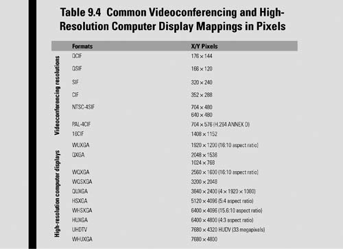
As a side note, high-definition analog broadcasting actually did begin at the end of 1949 as a 737-line interlaced format that could not be converted to or from other line or scanning formats. This French TV system was arguably the world’ first HDTV system. By today’ standards, the French system could be called 737i and possessed a maximum theoretical resolution of 408 × 368 line pairs (the digital equivalent of 816 × 737 pixels), but it had only a 4-by-3 aspect ratio (Table 9.4).
Analog, Digital, and Up/Down Conversions
Conversion from a raster perspective is fundamentally described as when one format is changed to a differing format with more or less video scan lines, a different aspect ratio or a combination of both. The process can be for either audio or video although audio escapes the concept of up- and downconversion—being replaced with mono, stereo, or multichannel/surround modification. Video conversion may be designated as upconversion, generally believed as taking a standard-definition picture and converting it to a high-definition image. Video conversion could also be a downconversion whereby a high-definition image is changed to a standard-definition image or a standard-definition image (SDTV as 720 × 486) is downconverted to a QSIF (quarter common immediate format) resolution bounded as 176 × 144 pixels, or to another mobile format for cell phones, smartphones, or apps.
Audio may be converted from analog to digital as AES3 or some other proprietary digital audio format. AES3 is the more common conversion practice, however some systems may also use the Multichannel Audio Digital Interface (known better as MADI), which is an electronic communications protocol defining a data format and an electrical interface for carrying multiple channels of digital audio. The audio could be stereo analog as two discrete channels that when converted becomes a single AES stream with two channels. There may be multiple sets of analog audio that are converted to multiple streams of AES or MADI. The streams may be further combined using industry accepted compression practices offered by Dolby, such as Dolby Digital (AC3) for transmission purposes or Dolby E for contribution purposes.
Depending on the application, external hardware for streaming signals, such as over an SDI transport, may be used or internal software (or hardware) that is integrated into a device, for example, a videoserver, would convert the signal formats on playout. The audio may be carried discretely as AES over an AES-3id transport or it may be embedded into the SDI video transport stream per SMPTE 272M-2004.
If the conversion process only produces a stream of digital bits, such as a high-definition SDI signal, the stream may never been seen as a file and would simply be sent to a real-time digital encoder, as is the case when an ATSC MPEG-2 encoder prepares the signal for over-the-air digital terrestrial broadcasting. Even in this ATSC example, if that same HD program segment were encoded into an MPEG-2 compliant ATSC transport stream (TS) with a fixed program length, this entire TS segment could be made into and stored as a file with all the appropriate syntaxes and elements. A transport stream server, could then release it to a television transmitter’ exciter, or transport the file over a network (or satellite link), or for direct playout through an MPEG decoder that converts that signal back into baseband HD video.
Format Conversion
Once an element of video or audio leaves the analog domain, goes through the digital conversion process, and then becomes a file, a number of additional parameters must be addressed. One of those parameters that must be specified is the encoding format. As an example, when the signal of raw essence, such as a 270 Mbit/second serial digital interface (SDI) video stream conforming to the SMPTE 259 standard is presented to the input of a videoserver, it is usually compressed to achieve a much smaller bit rate and then formatted for storage on a disk drive or other storage systems. The file created may or may not conform to a standard that is recognized by the industry. It may also be compressed to a known standard, for example, MPEG-2 MP@ML, but stored on the videoserver’ disk arrays in a proprietary format. It may be wrapped to MXF or to MOV when presented as a file to an outside network. If the devices and their files only needed to operate in a completely closed system, the vendor-specified proprietary format may be completely transparent to the outside world.
Hopefully, the user will choose a product that at the very least recognizes and follows a process for creating those files using known and recognized compression formats (e.g., MPEG-2, DV, etc). For interchange and openness, when those files are presented to another system, network, or device, the file should be properly wrapped (e.g., as QuickTime, MXF) as it moves from hard disk storage and onto the network connection, and then is placed onto another platform.
Sometimes, quite frequently now in file-based workflow, a file will use a wrapper or a compression format that is not compatible with the system, which will be discussed next. This could be due to the codecs available on the next server in the chain or because the files were not stored on a platform in a format and with a wrapper that is industry recognized. At this point in the workflow, the file would need to be transcoded in order for it to be recognized by another codec.
Transcode Pipeline
There are effectively two things that need to happen, depending on how the file is originally constructed and what the receiving end needs. If both ends of the chain (source and destination) can accept the same wrapper (or container) formats—as would be the case with an MXF source file format being delivered to an MXF compliant device on the destination end—then perhaps only a transformation of the coding format needs to occur. However, if the original file is QuickTime wrapped (i.e., a MOV QuickTime reference file), encoded as H.264 (AVC-intra), and the receiver expects to see MXF wrapped MPEG-2 422 Profile@ML, then both unwrap/rewrapping and format decode/ re-encoding must occur.
The workflow by which this transcode process happens follows the process of receiving a file and first dismantling it into individual audio, video, and data elements (picture, sound, and data essence). This step is called demultiplexing.
The next step then takes each of the demultiplexed elements and decodes them from the incoming compression format to a level where software can then transform those elements and reencode them to the output compression format required by the receiving (i.e., destination) device. Once properly encoded, the signals are recombined according to the parameters of the file format of the receiving device and then rewrapped into a container format also suitable for the receiving device.
Production-level transcoding requires significant compute horsepower; yet, today there are transcoding products on PCs and Macs that do “flipping” as part of their routine functionality. Early systems used server-class hardware and storage and required time frames usually in excess of real time just to do a simple conversion. Some users found that anything that consistently took longer than real time was better suited to a process where a videoserver just played back the content in real time and it was re-encoded into a different videoserver port or platform. This methodology becomes highly impractical and overly resource intensive when content is delivered only as files or when a high demand of conversion results in provisioning multiple sets of real-time hardware encoders.
Today, modern transcode engines operate with multicore processors or blade servers and can handle dozens of streams simultaneously and render multiple sets of files, each with different wrappers and compression formats. This is the growing trend in media workflow for file-based architectures. Figure 9.7 describes the functions typically found on a transcode engine’ user interface. This is the screen where most of the routine setups are made. This instrument becomes the place where the “workflow” is defined that produces finished files corresponding to the output requirements designated. Completed files are published to Web servers, FTP watch folders or to other devices downstream, such as videoservers or video-on-demand platforms.
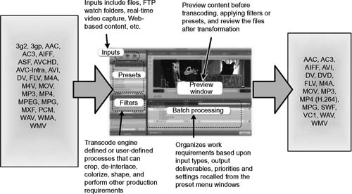
Figure 9.7 Typical transcode engine user interface where file format profiles, batch processing, and control of the filter and presets are enabled.
Multiplatform Conversion and Distribution
Earlier, we discussed the concept of a platform as being the fundamental technology of a system’ (e.g., a computer) hardware and software, which defines how a system is operated and determines what other kinds of services (e.g., software) can be used. In the sense of media files, there are four components that make up the platform (each of these components has been discussed at varying levels throughout this chapter):
•Codec
•Profile
•Level
•Container (wrapper)
When the user intends to deliver his or her video content to more than one platform, such as to an iPhone, to YouTube, for recording to a DVD, or to Blu-ray disc, the content will need to be transcoded. If in the production or asset management processes, there needs to be a master or house format created or a proxy generated so the assets may be found on a search mechanism, the process of transcoding must occur.
The transcoding process is done in software. It avoids “printing to tape” or returning to baseband for transfer as SD or HD video. Instead, transcoding includes the steps of taking the video file and decoding it, scaling it, and encoding it again so that it will work on the desired platform. After the file is prepared, it must be transferred, that is, moved from the source storage platform to the target platform.
Steps in Transcoding
The steps involved in a transcode process are further elaborated in Figure 9.8. Here, the file is first demultiplexed, that is, the file is unwrapped, taken apart, and converted into audio, video, and, depending upon the file, certain data (such as captioning or time code information) components.
Then, each of those components are decoded into their respective elements and then transformed. The transforming process may include something as simple as scaling from standard definition to high definition or it may involve altering the frame rate or scanning rate, cropping of the picture to fit a particular release format, or filtering to prepare it for the bandwidth constraints of the encoding process.
Transrating
The process of converting digital information from one transmission rate to another transmission rate is called “transrating.” In case of video, this could be a bit rate change that did not impact the coding of the video image. In audio, this could be a sample rate change. It is also frequently called “bit rate reduction.” This technology results in a continued high video quality level by effectively reusing information about the previous encoding while delivering a more cost-effective solution through smaller file sizes or more efficient transmission over the network.
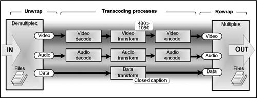
Figure 9.8 Abbreviated flow diagram for the steps involved in transcoding an A/V file, with ancillary data, from one format to another.
Benefits of transrating include the re-multiplexing of variable bit rate (VBR) streams, which is relevant for both DVB-T (terrestrial) and DVB-S/DVB-S2 (satellite) and for cable environments where the MSO wishes to pack as many programs into a given bandwidth as possible. Single MPEG-2 programs that are encoded as a part of a statistical multiplex (STAT-MUX) may vary in bit rate from 2 to 10 Mbits/second; transrating may be used to ensure that the operator does not have to reserve expensive, mainly unused overhead in the downstream network.
Other transrating features include the reduction of constant bit rate (CBR) streams, and IP streaming of MPEG-2 services where services are rate limited for a single service, enabling a CBR on a specified bit rate, typically significantly lower than both average rates of incoming CBR or VBR programs.
Finally, transrating aids in ensuring compliance with servicelevel agreements (SLAs) between network operators and content providers by limiting and controlling the rates of single programs that are retransmitted over a DTV network (e.g., a broadcast station that uses the full ATSC that allowed 19 Mbits for a single station may find the cable provider only employing 12–14 Mbits for the retransmitted signal in the same MPEG-2 format).
Transrating may be applied in an open-loop or closed-loop mode. The closed-loop method employs a “learning loop” that takes extra steps to reduce the bits in a stream by learning from what it processed just a few frames previously. These systems are sometimes known as multipass.
Broader Capabilities
Today, further capabilities are included in transforming such as the addition of logos, the concatenation of other files or formats, and even layering or transitional effects. In audio transformations, it may involve shuffling of the tracks in a multichannel stream, compression or band shaping, or changing from one sample rate (e.g., 44.1 kHz) to another (such as 48 kHz), and adjusting the bit rate from 24 bits to 16 bits.
If the conversion is from SD to HD and there is closed captioning data involved, then the data must be conformed from the SD version (as CEA 608) to the HD digital equivalent (as CEA 708). If metadata describes the audio compression format (e.g., Dolby E or dial_norm), then this must also be properly parsed and prepared according to the expectations of the final encoding format.
After the elements are appropriately transformed, then each of them will be presented to encoders before they can be made back into files. Encoding is set according to the MPEG or other encoding scheme, with the appropriate profile and level associated with the essence.
Once encoded, the individual essence components are remultiplexed and wrapped according to the file format requirements for final delivery to the storage platform, network, or editing system, which will next receive the file.
Real-Time Versus Off-line Transcoding
In the early periods when transcoding was mostly associated only with files and because of limitations on computing horsepower, most transcoding occurred in an “off-line transcoding” mode. Today, with the advent of real-time delivery, video-on-demand preparation, and high degrees of compression or software delivery, it is now common practice to segregate the transcoding processes even further
Real-Time Transcoding
Transcoding in real time is just what it infers; it is the processing of files as streams in hardware that is specifically purposed for live or nearly live delivery or transmission. The files are usually encoded at only fixed or constant bit rates, presented to the transcoding system as linear streams, and often built using hardware-based silicon components. This real-time processing is expensive compared to off-line transcoding systems. They are usually found in mission critical systems whereby a stream might be delivered to an over-the-air broadcast while simultaneously being delivered to the Web, near video on demand, or to a nonlinear editing platform for recutting during a live event such as a sport venue or a live breaking newscast.
From a performance and scalability perspective, two variables come into play: the number of channels or services required to be delivered to how many discrete platforms and the number of differing profiles that those channels must provide. For scalability, the real-time transcoding “farm” needs to identify how many channels will be required at peak times and how many output profiles are produced for those channels. These factors are influenced by the use case of the service level agreement (SLA) that the provider must account for.
Off-line Transcoding
This application hinges on the needs of a production service that is not dependent on a live or real-time delivery constraint. This is often the case when movies are ingested and then prepared for users on a variety of platforms. It is not unusual for a content aggregator or multichannel video programming distributor (MVPD) to end up producing a dozen or more formats from each movie master that is used by the Web, cable, satellite, packaged formats, on demand, etc.
In each of these respective releases, the transcode process may wish to employ VBR encoding, depending on the intended use. They are almost always producing files and not streams (although they could prepare files for streaming applications).
The performance and scalability of off-line transcoding has many variables. Factors that affect the performance of the system include the number of processors, the size of the memory, the bandwidth and amount of disk cache, and, if connected to other subsystems, the network the transcode farm is connected to. In terms of scalability, the system is measured by the number of transcoding tasks that can occur concurrently and in what amount of time. Again, the system must be considered on a usecase basis or according to the SLA the user and the customer has between them. Figure 9.9 compares real-time (i.e., “live”) transcoding to off-line (i.e., “faster or slower than real time”) transcoding functions.
Transfer Characteristics
Transcoding has helped to enable three modes of transfer, which are applicable, and now quite common, to the media industry regardless of the medium that is being used for the media. The three modes include streaming, download, and adaptive bit rate.
Streaming
Streaming occurs when video is pushed to or pulled from a server to a device that is then immediately, or very shortly thereafter, put into a playback mode. Selected examples of formats that are designed for this application form include the following:
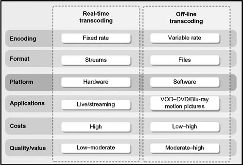
Figure 9.9 Applications and comparative value points in real-time versus off-line transcoding related to performance, hardware, cost, and application.
•Flash 7 (Adobe, formerly Macromedia)
•Flash 8 (Adobe, formerly Macromedia)
•Windows Media (Microsoft)
•Real Media (Real Networks)
•QuickTime (Apple)
There are also special cases where the streaming application is intended for a live event.
Download
Downloads are videos that are pulled from a server to a device, stored or buffered on that device, and then played back at a later time. Examples of video download include the following:
•Windows Media (Microsoft)
•QuickTime (Apple)
•iPhone Sideload
The special case for download is called “progressive download” that involves delivering video files using a Web server. Progressive is sometimes referred to as “HTTP streaming,” but it is not really streaming at all, only a simplified bulk download of a video file to a computer. Web servers will use the Hypertext Transport Protocol (HTTP) to transfer files over the network. HTTP operates on top of the Transport Control Protocol (TCP), which controls the actual transport of data packets over the network and is optimized for guaranteed delivery of data, regardless of its format or size.
With progressive download, the Web server does not care about the file size or the transfer rate, so the system just waits for the right network bandwidth and the file is delivered using a best effort model. Some WAN optimizers can aid in supporting download speeds, but those applications usually are disassociated with the Web servers that are preparing and submitting those files to the network.
Adaptive Bit Rate
When video is downloaded in small chunks and then played back one at a time, this is generally accomplished through the principles of adaptive bit rate encoding. Examples of adaptive bit rate encoding for streaming applications include the following:
•Dynamic Streaming for Flash (Adobe)
•HTTP Adaptive Streaming for iPhone/iPad (Apple)
•Smooth Streaming for Silverlight (Microsoft)
Examples and Conclusions
The flexibility offered in transcoding and transfer operations is growing more complex and more valuable as each new compression format is introduced and as each new device or delivery platform is marketed. These multiformat, application-targeted models allow users to choose the appropriate configurations for the needs of the organization, customer, or user. Through the deployment of these conversion, transcoding, and transfer models, it has become possible to stream in multiple formats, deliver in multiple resolutions, and produce variations in bit rates simultaneously so as to optimally reach a diverse new set of audiences.
Figure 9.10 shows the integration of a transcoding platform with a decision tree that automatically can properly conform standard-definition or high-definition video files to a prescribed release format based on the user describing how those images should be prepared and in what aspect ratio and image format (SD or HD). This is just one segment of what might comprise a complete workflow model for the ingesting, processing, preparing, and delivery of file-based media and content.
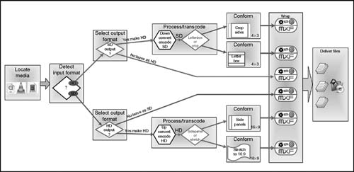
Figure 9.10 Example of a media aware process for delivering SD or HD source files in any of the five different final output formats while staying entirely in the file-based domain.
Further Readings
Useful references to video, audio, and other file formats: http://www.fileinfo.com/filetypes/video
SMPTE and EBU work and study project that resulted in the foundation for file-based workflows: “Task Force for Harmonized Standards for the Exchange of Program Material as Bitstreams,” Final Report: Analyses and Results, July 1998.
The document can be found at
http://www.smpte.org/standards/tf_home/Final_Report_-_Findings.pdf
SMPTE Standards that are informative with respect to the MXF standards include (a) ANSI/SMPTE 298M-1997, Television—Universal Labels for Unique Identification of Digital Data; (b) SMPTE 336M-2001, Television—Data Encoding Protocol using Key-Length-Value; (c) SMPTE EG 42—MXF Descriptive Metadata.
A listing of the MXF Operational Pattern standards that include (a) SMPTE 390M: OP-Atom; (b) SMPTE 378M: OP-1a (the minimal and simple MXF file); (c) SMPTE 391M: OP-1b; (d) SMPTE 392M: OP-2a; (e) SMPTE 393M: OP-2b; (f) SMPTE 407M: OP-3a, OP-3b; (g) SMPTE 408M: OP-1c, OP-2c, OP-3c.
Guides to digital audio practices, conforming files and audio to meet the various industry standards, and practical applications for multichannel sound can be found at
Dolby Laboratories.
http://www.dolby.com/professional/technology/index.html
Linear Acoustic.
http://www.linearacoustic.com/wpapers.htm