15
NETWORKED STORAGE
The key to successful modern storage implementations is in assembling a system of components that interoperate well, can be cost effective, are easily managed, are able to expand to meet capacity demands, and have sufficient bandwidth so as to not become the bottleneck when placed into an enterprise-level storage environment. And by the way, the system must operate 24 × 7 × 365, be reliable and inexpensive, and must provide levels of protection including redundancy so as not to be a risk to the myriad assets it will handle.
The role of storage systems continues to evolve. The explosion in the volume of media assets that need to be managed, coupled with how businesses must now operate to meet their objectives, has given way to new sets of requirements and expectations. In Chapter 1, we discussed the notion of data and information, but we have only touched upon how those entities are stored and managed, each of which are important elements that return value from any system.
In a storage network for computer systems, the bits and bytes that make up the data sets can reside most anywhere on the storage devices. Data is turned into information by applications that address the meaning of the bits and bytes. However, in a media-based system, storage systems need to take on different roles. Storage systems designed for media applications must operate like transaction-based systems in the financial world, as in if they cannot respond to the user’s needs immediately when called (i.e., demanded) upon, then their value reduces to a near-zero level.
In later chapters, we will explore intelligent storage and virtualization, and how they help support users that deal with different storage platforms being accessed by an increasing number of servers and applications; additionally, we will look at storage is managed.
This chapter discusses the concepts of storage networking as applied to both computer data and media systems. We will look into Fibre Channel and “networked” storage systems, not just the specifics related to storage area networks (SAN) or network- attached storage (NAS), which are elements of an overall networked storage solution.
KEY CHAPTER POINTS
•Networking concepts applicable to storage technologies, the OSI model, and the Fibre Channel protocol stack are introduced.
•Data networks, communications, and voice and storage networks are compared.
•Filing systems and block-level and file-level functionalities are applied to storage networking.
•Direct-attached storage (DAS), network-attached storage (NAS), and storage area networking (SAN) are defined and compared.
•SAN architectures, and the planning and scaling of SANs for new and legacy systems are discussed.
Networked Storage—Fundamentals
Storage networks consist of elements that when efficiently combined will form a system that can fulfill the needs of the devices that must store data, interchange data, and retrieve that data for those applications that the data supports. In addition to these requirements, networked storage systems must further provide flexibility, adaptability, maintainability, resilience, and fault tolerance.
Storage System Environment
The highest level components that make up the environment of a storage system consist of the host, its connectivity, and the associated storage. In a host, which is the entity that contains the applications and runs those applications, usually the physical components include the central processing unit (CPU), the storage devices including internal memory and disk drives, and the input/output devices.
The storage medium that stores the data can be subdivided into temporary (cache) and persistent (long term). Memory in the host can be random access in nature, such as RAM; or nonvolatile read-only memory such as ROM. Semiconductor memory, such as RAM or ROM, once a premium for host devices, is no longer a cost factor. It is common to find workstations with as much RAM as most computer disk drives held a few short years ago. The physical media used for the long-term storage of persistent data generally resides on hard disk drives, optical (CD, DVD, and Blu-ray Disc), or magnetic tape media (LTO or DLT).
Communication Channels
The physical components that enable the sending or retrieval of data to or from a host communicate by using basic input/output (I/O) human interface devices (HID) such as a monitor, a mouse, and a keyboard (see Fig. 15.1). For host-to-host communications, a network device such as a modem or network interface card (NIC) is required. For a host to a storage device, a port will provide connectivity through an adapter, such as a host bus adapter (HBA) that is designed to be an application-specific purposebuilt device to address the interfaces and protocols of the storage system. The HBA relieves the CPU from I/O processing workloads that would otherwise contribute to system bottlenecks or reduced throughput.

Figure 15.1 Components for physical connectivity.
Logical and Physical Connectivity
Networking has depended upon the Open Systems Interconnections (OSI) model for decades, even before the Internet and long before high-speed systems such as GigE (Gigabit Ethernet) came into existence. The OSI model has two major components: an abstract model of networking, called the Basic Reference Model, better known as the seven-layer model, and a set of specific protocols.
Open Systems Interconnection Model
The OSI model was originally developed in the late 1970s under the auspices of the ISO and became a framework for modern day implementation between various elements in a network. The depth of this model is beyond the topics in this book as there are many written dissertations about what this architecture is, and how it is utilized. Nonetheless, it is good to know some of the basic concepts so as to understand statements such as “layer 2 switching” in a switched network topology.
The basic overview of the OSI model follows, with references to Figure 15.2.
Layer 1: Physical
This layer defines the physical and the electrical requirements for devices. It includes the relationship between the physical transmission medium such as copper or fiber optic cable and the device itself.
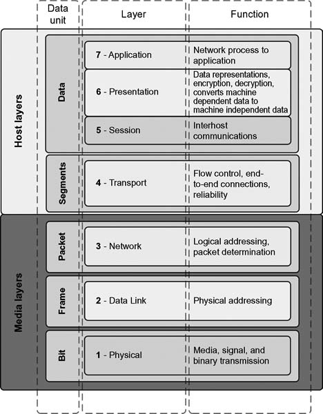
Figure 15.2 Open Systems Interconnection (OSI) model.
When two computers are connected together, they require a physical connection, connectors, and a wiring or transmission method such that data can flow from one device to another. Layer 1 is where raw, unstructured bits move from the connector through some form of media (fiber, twisted pair, coax, and even the air) to the other connector. Layer 1 also describes how media are connected to a NIC. It includes information about connector pinouts, electrical or optical levels, and functional characteristics about the media connection methods.
Layer 1 is concerned only with raw bits that have no specific meaning when compared with the original application. Layer 1, however, is also responsible for ensuring that if a bit was sent out as a “1,” it is received as a “1.” Further information is also represented, including data encoding, synchronization, length, and electrical characteristics of the bit and its type or form, for example, if the pulse is negative going, balanced, or differential.
To compare this in video technology, Layer 1 might be equated to the BNC connector on the back of the distribution amplifier. In video, it must be a true 75-ohm connector that meets a specification of particular size, electrical specificity, and material.
Layer 2: Data Link
This layer provides the functionality and procedures necessary to transfer data between network entities, and to detect and potentially correct any errors that may have occurred in Layer 1.
Layer 2 interfaces data from the lower Physical Layer to the layer above it, the Network Layer. Layer 2 translates the raw bit stream into data frames or packets that make sense out of the bit stream before it is acted upon by the Layer 3. A data frame consists of the elements shown in Figure 15.3. The forward most portion of the data frame is called the header. Just like the information on the envelope of a letter, there is a sender ID and a destination ID. A control ID is added as a guide for functions such as synchronization, routing, or frame type. The bulk of the data frame is the actual data (the meaningful information that needs to find its path to the Application Layer). Finally, a trailer or cyclic redundancy code (CRC) is attached for error correction and frame verification.

Figure 15.3 Basic data frame construction.
At each of the layers, this root process is ordered, defined, and adhered to so that the interchange between the layer below it and layer above it is consistent regardless of where the hardware or software resides. Enough information is contained in each data frame so there is certainty that data from a word processing document will end up as a word processing document, although many more functions occur before the data really “appears” as a word processing document.
Layer 3: Network
Aimed at maintaining the quality of service requested by the Transport Layer (above it), Layer 3 provides the functional and procedural requirements for transferring variable length data sequences from the source through the networks. This layer performs routing functions in a logical addressing scheme so that data may be sent throughout extended networks.
This is the upper level for network services. Layer 3 addresses packet or data frame switching and is where the virtual circuit is established, that is, the translating of logical names and addresses into physical addresses associated with the connection method. The Network Layer determines the data path within the network based upon network traffic and congestion.
Another function of Layer 3 is to resize the data so that it fits within the confines of the router. Should data be too large to squeeze into the space defined by the Data Link Layer below it, the Network Layer will break data into smaller units and send it on. At the other end of the virtual connection, the information sent along from this layer enables reassembly of the packets into meaningful data as it passes up through the network layers and on to the application.
Layer 4: Transport
This layer effectively provides a transparent interchange of data between end users, including reliable data transfer services to the layers above it. Through flow control, segmentation and desegmentation, and error control, this layer controls the reliability of a given link within the network architecture.
The barrier between the Network Layer and the Transport Layer is a zone where many anomalies must be accounted for. Packet orders may be wrong, bit errors must be accounted for (and corrected), and even the multiplexing or demultiplexing of several messages on the same bit stream must be accomplished.
Layer 4 manages these functions. Here, another piece of header information is added to the packet that identifies it to the Transport Layer when it is received on the other end. This layer regulates data flow by controlling the message based upon the priority that it received. Layer 4 also resolves receiver and transmitter problems associated with all the packets that pass through its layer. This layer is responsible for sending acknowledgments forward or backward through the network stating that the data is either okay or needs to be resent because errors that it detected were unrecoverable.
Still left to discuss are the three remaining layers, Session, Presentation, and Application. From now on, the tasks become more complex and more information is added to (or stripped from) the overall data frame or packet as you move through the OSI model.
Layer 5: Session
Connections, known also as dialogs, between computers are managed and/or terminated between the local and remote applications.
Up to this point in the OSI model, the emphasis has been on bits and messages within the bit stream. The user on the network has been of no concern so far. Layer 5 is that portion of the network model that establishes when the two computers begin, use, and end this virtual connection. As the name implies, this period of use is called a “session.” When a session is started, whether for simplex (one way), duplex (two way), or half-duplex (both directions on the same link, but reversing), this layer sets the checkpointing, any restart procedures, and the adjournment (termination) of that particular session.
You can think of a session on a network connection like a video editing session. Similar types of events happen. For example, a client books a session with the editor, who allocates either directly or indirectly the edit suite and associated equipment, and then requests the use of certain pooled resources for that particular edit session. Then the editor initiates the edit session by creating a name for the session. Starting with “edit#1,” then “edit-#2,” and so on, a number of active elements in each edit (or event) are arranged to create an overall flow to the program. The edit listing might not be in sequential order in the edit decision list or on the working screen. That is left to other tasks, but the process where these tasks are grouped is called a session. The session therefore becomes the binder of the processes.
Layer 5 also places markers that act as checkpoints in the data stream. These markers provide synchronization that in turn allows the session to resume, from that point forward, should a failure occur that temporarily interrupts that session. A network failure may be catastrophic or completely transparent to the user. Something as simple as a continuous collision of data or a hiccup on a router might signify a millisecond pause in the session and may not be visible without a network analyzer. However, these are things that slow down performance and become part of the software tuning that network LAN engineers and specialists look for in peaking up a network’s overall throughput.
Layer 5 goes a few steps further. Its traffic control function determines when transmissions can occur, who goes first, and how long they will have to transmit. These sessions are virtual in nature and occur continuously with numerous other activities on the network overall.
Layer 6: Presentation
Layer 6 is the network’s translator. It formats the data to and from the previous Session Layer so that it can be interpreted and utilized properly at the final stop, the Application Layer.
In Layer 6, protocols are converted, for example, from “terminal protocol” or “transmission protocol” into another protocol. This is where encryption and decryption occur, and where character sets (ASCII or EBCDIC) are managed. Data compression is also managed at Layer 6, and a function called redirection (which relates to server I/O operations) also occurs.
Layer 7: Application
As the topmost layer, Layer 7 acts as the gateway to the actual user-specified applications such as higher-level applications, email, and multimedia. Layer 7 is responsible for remote log-ins and the statistics of network management. This is the layer that is adjusted to fit specific industry needs. As such, and because different user programs have different requirements, it is difficult to describe the details of the protocols found at this level.
Layer 7 determines the identity and availability of communication partners for an application with data to transmit. For resource availability, Layer 7 decides whether there are sufficient network resources or the requested communication exists. Synchronizing communication between applications requires cooperation that is managed by Layer 7. Implementations handled by this Application Layer include Hypertext Transfer Protocol (HTTP), File Transfer Protocol (FTP), and Simple Mail Transfer Protocol (SMTP).
Networks
To set storage networks into perspective, we need to differentiate the types of communication networks as to their functionality.
Voice Networks
This was once the preeminent network before the generalization of the term network was commonplace. This, obviously, is the ever familiar telephony systems that at one time were managed by a human operator who literally plugged connections between one or more parties together. The voice network continued, albeit aided by analog switching technologies, up through the era of the digital switch. Today, the digital telephone network dwarfs the capabilities of the early analog connectivity and employs far more sophistication than ever before given the multidimensional services that voice communication systems have evolved to.
The integration of voice into data networks has become a reality. Packetized voice communications have enabled the transport of voice over the same networks that transport data now.
Data Networks
At its most simplistic level, a data network is an electronic communication process that allows for the orderly transmission and reception of data. The data may be files containing video and audio essence or metadata, email communications, or documents such as letters or spreadsheets. A primary difference that sets the data network apart from other forms of communication, such as an audio network, is that the data network is configured to transmit only data. It may be a simplex (one-way) or duplex (two-way) network. In contrast, the voice network, often employed for both voice communications and the transmission of data such as a facsimile transmission, is designed as a two-way system, that is, it must receive and transmit data.
Two basic types of data networks are in operation today—private and public. A private data network is essentially a local network designed for the transmission of data between the various groups or departments within a given entity, typically a business or a household. All the locations in that business may be included as nodes on the network. They communicate through a common server that functions as the repository for all data files that are used throughout the business. Private data networks may allow for data sharing between several geographic companies that are part of the same enterprise organization, usually on a closed basis. Connections made on this type of network are achieved through a virtual private network (VPN) that is resident on the primary network server or through connections provisioned by a communication carrier.
By contrast, a public data network is widely accessible to both residential and corporate clients on a given carrier network. Public networks may involve the utilization of multiple servers and connection to the network through several different processes. Public data networks involving a carrier are usually fee based. Through a subscription, the service provider creates a set of access credentials that permit the consumer to access authorized portions of the network and engage in functions commonly involved with data.
Public networks, such as those provisioned by a cable company, become a gateway to the Internet, a global system of interconnected networks that use the standard Internet Protocol Suite (TCP/IP) to serve users worldwide. The Internet has become a network of networks consisting of millions of private, public, academic, business, and government networks interconnected by a growing array of electronic and optical networking technologies. The public Internet is employed to carry information resources and services, best known as the interlinked hypertext documents of the World Wide Web (WWW). The “net” also has enabled the global infrastructure to support electronic mail.
Introducing Storage Networks
It was not long ago that data was stored on disk and data tape drives that were directly connected to the serving platform. Storage was seen as a peripheral to a computer and later on a server. Storage of media resources has similar parallels, stored first on videotape, and then as digital video emerged, that content was stored to disks on editing systems or on digital disk recorders (DDRs) for the short term.
In the data world, functions including access rights, security, virus protection, etc., were performed on the server. In the videotape-based media world, there were no security rights, no electronic access control, and no “requirement” for virus protection. Content would be physically contained on a videotape, protected only by the holder of that tape, a vault or a lock drawer. Once digital nonlinear editing was introduced, the potential for storage grew with the transport being either real-time video (over a broadcast centric infrastructure) or via a point-to-point interconnection over Ethernet. Nonlinear editing rapidly changed the video paradigm as it moved from tape ingest/tape output to the all digital file-based infrastructure, which we are familiar with today.
Storage networks are the extension of these models. For data, servers can be added with or without sufficient disk storage to manage the information sets it will process. For media, multiple sets of editing and processing hardware (servers and computers) can be added, but the storage requirements for these activities can be quite different than those for conventional data storage.
For these applications, there were growing needs to interconnect servers, computers, and islands of storage that for the most part remained as locally isolated platforms interconnected by conventional networking components such as NICs, twisted pair cables, and switches. The storage network began from a desire to serve those needs and has since become its own entity with choices including network-attached storage (NAS), storage area networks (SAN), and others.
Storage networks have become a fundamental technology just like local area networks and databases. They have opened up a wealth of new opportunities for the management of data as information. Storage networks have different requirements to fulfill, as with server-centric IT architectures.
Direct-Attached Storage
When storage is attached directly to the server or the host computer, this is referred to as “direct-attached storage” (DAS). DAS may be classified by the location where that storage resides, with respect to the host. For the purpose of continuity, we may assume that a host might be a server, a computer, or a device that performs services as applications.
DAS may be classified as either internal DAS or external DAS. Applications access DAS at block-level protocols.
Internal DAS
When the storage is physically located within the perimeter boundaries of the host and generally connected either by a parallel or a serial connection, it is considered internal direct-attached storage. Internal DAS is usually distance restricted to allow for high-speed connectivity. The internal bus architecture is limited to a finite number of devices that can be connected to the bus.
External DAS
When the host connects directly to storage via a protocol such as SCSI or Fibre Channel (FC), it is considered external storage. Again, these are one-to-one to one-to-a-few connections that still remain relatively close, physically, but are generally found to utilize much larger volumes of disk storage and, therefore, do not generally remain inside the host chassis. Figure 15.4 shows an example of how clients and servers would use external DAS.

Figure 15.4 Direct-attached storage (DAS).
Interfaces for DAS
DAS, which was the original form of storage for host communications, requires a relatively low level of interface at a substantially less costly amount of investment. DAS, however, is limited in terms of scalability. Disk utilization is governed by the performance of DAS. Its throughput, cache memory, and lack of virtualization capabilities limit the implementation of DAS to all but a few applications.
Host and storage devices communicate with each other through predefined protocols that have been standardized and implemented on the disk drive controller. Chapter 5 covers the details of how the buses, ports and interfaces for DAS (and other disk systems) are interconnected to computers and hosts through various protocols which have continued to evolve through modern times.
Parallel SCSI and IDE/ATA specifications were the predominant interfaces when disk drives became more closely associated with PCs and local workstations. The PC world used IDE/ATA, and the Mac world seemed to go the SCSI route. The limitations of SCSI and IDE/ATA parallel cabling forced the migration to serial interfaces of the same or quite similar protocols on twisted pairs or sets of cables.
Filing Systems
The filing system and the storage system typically function in a master/slave relationship. The storage devices are typically slaved to the filing systems that write data into and read data from them. Filing systems may be either file systems or database systems.
File systems include the following:
•NTFS (Windows XP, 2000, NT, Vista, Windows 7)
•CDFS (Linux virtual file system)
•exFAT/FAT64
•UDFS (user defined file system)
•FAT and FAT32
•Unix file system (UFS) with its variants
Database systems include the following:
•Sybase databases
•SQL databases
•Oracle databases
•Informix databases
•Veritas file system (VxFS)
Filing System Functions
In a broad view, there are two functions that filing systems will do: represent data to users and applications, and organize where that data is in storage. Data is typically organized in directories or folders in some hierarchical fashion. It depends upon whether that data is structured or unstructured as to how that data is actually organized.
Block Level
Filing systems organize where that data is placed in storage. Because of the drive architecture of most storage systems and to obtain reasonable access performance, the filing systems will scatter the data throughout the storage container (system) as part of its policies to make sure that all data can be accessed with a minimal impact to the users and applications. The structuring of this data is achieved by using the storage block addresses to determine where the data is placed. Because the disk drives maintain their own block translation tables, these storage block addresses are actually logical block addresses that point to the disk drive tables, which are the real knowledge base of where the data can be found on a block-by-block basis.
To summarize, block-level storage refers to the filing system sending commands to slave storage that instructs the storage on how to write and retrieve data from certain blocks.
File Level
Filing systems may be called upon to request data using what is called file-level storage. Here, the user-level data representation interface is done by the client using the data’s filename. The name may be a directory location, a uniform resource locator (URL), or another data naming or locating principle. This methodology is referred to as the client/server communication model.
Functionally, the server receives a filing request, it looks up the data storage locations where the data is stored, and then it retrieves the data using block-level storage functions. The server sends this file as bytes, not as blocks because file-level protocols lack the ability to understand block-level commands. In contrast, block protocols are unable to convey file access requests or responses.
Filing and storing are tightly coupled, meaning that one cannot work without the other. The functions can exist on the same network; however, storing and filing traffic are transferred over a bus or a network independent of the physical connection or wiring used in support of the communications. It is the storage application protocols that differentiate the file-level from the block-level storage methodologies.
Network-Attached Storage
With the previous discussion on filers or filing systems, the next logical progression in storage is network-attached storage (NAS), the name for a preconfigured file server. The most elemental form for a NAS server is a set of components that are wrapped together and include one or two servers, some capacity of preconfigured storage, and a rudimentary special operating system (OS). Figure 15.5 shows a NAS server, where the server and the storage are integral components. The alternative is a NAS gateway, where the server appliance is placed external to the storage and interface components.
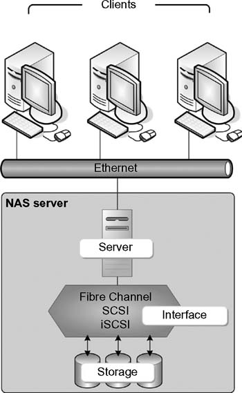
Figure 15.5 NAS server with the storage and interface preconfigured and integrated into a single package.
When the storage is external, a preconfigured server, called a NAS gateway, becomes the interface between the clients on the network and the storage interface (e.g., Fibre Channel, SCSI, or iSCSI). This configuration is shown in Figure 15.6 where a server with a scaled down operating system becomes a mid-level storage interface controller/ file server.
NAS servers are specifically designed for file sharing, which allows the integrated and optimized operating system to focus on just those activities associated with receiving and delivering files over the network. This distinguishes the NAS server from the file server by allowing it to operate faster and be installed and configured quicker. This also allows for the NAS server to be very scalable.
In an organization, a NAS server could be dedicated for every project, for each editing group, or for individual departments. If an editing project or a feature production needed more storage, simply add it onto that network segment and work continues.
One caution: NAS server upgrade paths may be unclear and are limited to what the manufacturer has provided. Adding a server with better performance may not be possible without adding an entire new NAS system. NAS servers are not particularly well suited for intensive operations, such as databases, backups, or batch processes. Certainly some NAS products have been fully optimized for these kinds of activities or specifically for media-centric applications (such as scale-out NAS from Isilon (now a part of EMC) or from NetApp’s unified storage architecture), but the more generic NAS products have much broader service applications, such as for email or websites.
Multiple Protocol Support
NAS servers often support multiple protocols, such as the older AppleTalk (since displaced with Mac OS X), the Server Message Block (SMB) or Common Internet File System (CIFS), and common network protocols such as Network File System (NFS), File Transfer Protocol (FTP), and Hypertext Transfer Protocol (HTTP). These protocols may not have sufficient performance for I/O-intensive operations even though they are designed for traditional file sharing activities. Note that I/O-intensive operations typically employ disk storage subsystems, not file servers, from which to draw their storage.

Figure 15.6 NAS gateway configuration with external storage.
Acceleration
Manufacturers that provide NAS solutions may build accelerators into their platforms that support specific performance functions and high availability. When file sizes get very large, typical to media operations such as high-definition video or Digital Picture Exchange (DPX) files used in the preparation of digital intermediaries or digital cinema releases, disk bandwidth becomes a governing factor that most storage architectures ignore. A high-performance NAS system must be capable of operating with a wide variety of file sizes. The environments found in motion picture productions, effects, and editing require massively concurrent access to many small files (metadata files, short clip segments, or graphics); but must also provide for high-throughput sequential data access to single large files.
File Size Optimization
NAS, when used in node or clustered configurations, allows the disk side of the storage platform to be optimized for a variety of file sizes. The operating system associated with the NAS can use different approaches in handling smaller files versus handling large files. Such an OS must be adaptive and leverage the CPU power against the I/O disk in order to increase performance for all file configurations.
Direct Access File System
Similar to NFS and CIFS, Direct Access File System (DAFS) allows applications to transfer data while bypassing operating system control, buffering, and network protocol operations that can bottleneck throughput.
DAFS Protocol
Remote file-access protocols have been in widespread use for more than 15 years for workgroup data sharing. Advantages have increasingly made DAFS attractive to the data center for use in database and local file-sharing applications.
DAFS is designed to take advantage of direct access transports (DATs) to achieve remote file access at CPU overheads that are as good as or better than what is achieved through block access, while retaining the advantages of the shared file-access paradigm.
The transport mechanism used by DAFS is the Virtual Interface (VI), a hardware application that transfers data to and from application buffers without using the operating system. This concept frees up the processor and operating system to perform other processes, allowing files to be accessed by servers using different operating systems. DAFS, a remote file-access protocol that uses a request-response protocol (like that in NFS), was designed for optimized clustered, shared-file network environments, for Internet, e-commerce, and database applications. It is also optimized for high-bandwidth InfiniBand networks and works with any interconnection that supports VI including Fibre Channel and Ethernet.
NetApp (Network Appliance) and Intel formed the DAFS Collaborative, an industry group of more than 85 companies whose target is to specify and promote DAFS. In 2001, SNIA (the Storage Networking Industry Association) took over that work.
Recent developments (2008) in system area networks have produced a new networking paradigm, that is, direct access transports (DATs). DATs exploit the remote direct memory access (RDMA) suite of capabilities that will enable enormous improvements in the performance, scalability, and reliability of data centers.
Examples of networks that support direct access include Virtual Interface on Fibre Channel (FC-VI), InfiniBand (http://www.ibta.org/), and the Remote Direct Data Placement (RDDP) protocol for the Internet (http://www.ietf.org/html.charters/rddp-charter.html and http://www.rdmaconsortium.org/).
Storage Area Network
A storage area network (SAN) is a high-speed dedicated network of shared storage devices and servers that is traditionally connected over Fibre Channel networks. It carries data between servers and to storage devices through switches specifically designed to carry the Fibre Channel (FC) protocols.
Before one looks at the SAN, an understanding of Fibre Channel is necessary, given that the concepts and functionality of a SAN grew out of the efforts of Fibre Channel technologies. The following sections provide an introductory thumbnail overview of Fibre Channel. This technology is one of the faster growing segments of networking architectures with multiple technical committees inside of INCITS continuing to provide many extensions to FC.
Fibre Channel Networks
Standardization and adoption of FC began in the 1988 time frame when it was introduced through the chartered efforts of the Fibre Channel Working Group to the American National Standards Group (ANSI). FC developed as an extension of work on the Intelligent Peripheral Interface (IPI) Enhanced Physical standard. FC was originally designed as a backbone technology for LAN connections. It would be six full years later before the interconnection standard would be adopted, and the Fibre Channel Association (FCA) would be founded.
As a high-speed network technology, FC initially had a throughput of 100 Mbytes/second, a much improved implementation over the 20 Mbytes/second speed of its closest competitor, Ultra SCSI, which at the time was the state-of-the-art for DAS. When configured in full duplex mode, FC can sustain a throughput of 200 Mbytes/second, with the latest improvements hitting 8 Gbits/second (in 8 GFC) for 1600 Mbytes/second, and product announcements (by QLogic in September 2010) for the 16 Gbits/second standard ratified by 16-Gbits Fibre Channel standard ratified by the ANSI INCITS T11.2 Technical Committee and announced by the Fibre Channel Industry Association (FCIA).
Channels and Networks
Fibre Channel combined two opposing methods of communications, channels, and networks to create the best of both worlds.
Channels operate in a closed master-slave environment. Channels are used for transferring data with error-free delivery and a lessened concern over transfer delays. Networks operate in an open, peer-to-peer, and unstructured environment. Networks transfer both data and media-related information that is time dependent—where error-free delivery is secondary.
Network communications offer more flexibility than channel communication technologies. Networks provide for greater geographic separation, and they are less encumbered by the effects of distance. For PCs, networks provide connectivity to, for example, servers and server-based applications, file and print services, and internal or dedicated intranets. This kind of network provides shared bandwidth and the capability to communicate with different systems. Network technologies also have the characteristics of lower performance than a channel, a high-protocol overhead, and a dynamic configuration.
Fibre Channel captures many of the benefits of both networks and channels. Before undertaking the design of a fabric, an understanding of Fibre Channel is essential. Going from DASattached SCSI to Fibre Channel—as SCSI over Fibre Channel—allows one to overcome the distance issues associated with SCSI and the scalability and accessibility issues of DAS, and allows for dynamic flexibility; all of the latter being better suited to FC than DAS or even NAS.
Fibre or Fiber
The spelling of Fibre Channel was chosen (“Fibre” as opposed to “fiber”) because the physical serial media can be copper wire, coaxial cable, or fiber optic cable. The word “Channel” in this case does not refer to the channel protocol as described above.
Initiators and Targets
One of the terminology pairs found in describing data interchange grew out of the work on SCSI. Here devices identify themselves using a SCSI ID, a unique number that addresses each unique device on the bus. By itself, the SCSI bus can address up to eight logical units (LUNs). Typically, the numerical ordering for the LUNs is from 0 to 7, and each LUN can play the role of either a target or an initiator.
The “initiator” will generally issue a command or request, and the “target” will execute that request. SCSI, by design, must consist of at least one initiator and one target device, although some SCSI devices can act as both initiator and target.
Topologies
Three topologies are provided in the FC standard: point-to-point, a bidirectional connection between two devices; arbitrated loop (AL), a unidirectional ring whereby only two devices can ever exchange data between one another at a time; and fabric (sometimes capitalized as Fabric), a network that permits multiple devices to exchange information simultaneously without additional bandwidth restrictions. Arbitrated loop and fabric topologies are incompatible with each other due to the differences in their protocols.
Common to each of these topologies are the storage devices, servers, and switches. The fabric topology is the most common as it utilizes the best performance advantages of FC. Core-edge fabric is a popular design topology with multiple variations; mesh being one that is commonly deployed in SAN implementations.
Fibre Channel is not bound by dependency upon any one topology. This differs from what many were used to in network topologies such as token ring (IEEE 802.5), Ethernet (IEEE 802.3), and FDDI. Nearly all network transports are prohibited from sharing the same physical media because their access protocols were constructed strictly for only one use.
Fibre Channel was intentionally designed to support multiple topologies. Inherently a closed system, Fibre Channel relies on ports logging in with each other. If the topology is a fabric, it must trade information on characteristics and attributes so a harmony exists from the start of the session.
The important principle to realize is that management issues related to the topology have no bearing on Fibre Channel. Whether the fabric is a switch, a hub, a LAN/WAN, or a combination of the above, Fibre Channel expects the management to be handled externally from the process of configuring and moving frames and sequences around the connected network.
The selection of a topology for Fibre Channel is based upon system performance, budget, extensibility (growth), and hardware packaging.
Nodes, Links, and Ports
“Nodes” are Fibre Channel devices, each of which has at least one port. Workstations, disk arrays, disk drives, scanners, etc., can all be nodes. Ports provide access to other ports on other nodes. A “port” generally consists of an adapter and a certain level of software. When there is more than one port on a host node (i.e., a primary CPU or server), the software may be shared across all the ports—making the distinction between port and node somewhat fuzzy.
“Links” are pairs of signal-carrying media (two fibers, a pair of twisted copper wires, or two coaxial cables) that attach to the node ports. One carries data into the port, and the other carries data out. The topology of the Fibre Channel system consists of the physical media, transceivers, and the connectors that connect two or more node ports, which are interfaced through a global link module (GLM), an avenue that easily converts between fiber optic cable and copper wire as a connection medium.
FC Protocol Stack
The FC protocol stack is divided into four lower layers that describe the transmission technology (FC-0 through FC-3), and the upper layer (FC-4) that defines how the applications’ (e.g., SCSI and IP) protocols are mapped onto the FC network.
The layering model for Fibre Channel is shown in Figure 15.7. The interface connection enters at the Physical portion (FC-0) of the model, shown at the bottom, and moves upward through the various levels until routed to appropriate other channels or networks. These levels are bidirectional, with each successive handoff from one level to the next having introduced all the necessary information to make flow possible, regardless of the connection on either side of the level boundaries.
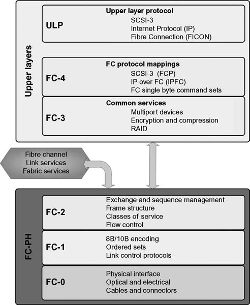
Figure 15.7 Fibre Channel protocol stack.
Physical Layer
The Fibre Channel Physical (FC-PH) interface, layers 0 through 2, was the first to be standardized. Historically, the first review of FC-PH was in January 1993, and the second review began in October 1993. FC-0 accepts the physical media input; at the time of the standardization, at specific speeds from 131 Mbits/second through 1 Gbit/second. Since then, this growth has now reached 8 Gbits/second.
The layering model for Fibre Channel is shown in Figure 15.7. Although the model continues to evolve, from a standard point, the FC protocol stack is like the OSI model for networking familiar to most IT-network technologists.
The interface connection enters at the Physical portion of the model, shown at the bottom, and moves upward through the various levels until it is sent to appropriate other channels or networks. The principle in these levels is that the signal path becomes bidirectional. Each successive hand-off from one level to the next has introduced all the necessary information to make flow possible, regardless of the connection on either side of the level boundaries.
From this point, the system makes the proper translation into the FC-1 level where the transmission protocol is defined. At the FC-1 level, 8B/10B encoding, error detection, and order of word transmission are set up. From here, in FC-2, the signaling protocol and framing, sequences, and exchanges are established.
FC-2 manages the exchange and sequence of data, the frame structure, the classes of service, and flow control. Once the properly configured data leaves the FC-PH standard, it enters the common services level, which is considered the entry point to the upper layers and upper layer protocols (ULPs) of the Fibre Channel stack.
Upper Layers
Fibre Channel’s level FC-3 and level FC-4 are the two top levels of the Fibre Channel architectural model.
Level FC-3 is the level intended to provide common services and those necessary for advanced features. Striping is one of these proposed features. The intent in striping is to multiply bandwidth using multiple N_Ports in parallel to transmit a single information unit across multiple links.
Hunt groups, another of the common services in FC-3, are a set of associated N_Ports attached to a single node. When assigned a special identifier, any frame containing that identifier can be routed to any available N_Port within the set. This effectively permits more than a single N_Port to respond to the same alias address. By decreasing the chance of reaching a busy N_Port (one that has already been connected to another port), efficiency will be improved.
Multicasting is the delivery of a single transmission to multiple destination ports. This includes broadcasting to all N_Ports on a fabric or to a subset of the N_Ports on a fabric.
The highest level in the Fibre Channel stack is FC-4. This, like the highest layer in the OSI model, defines the application interfaces that can execute over Fibre Channel. Here, mapping rules for the upper layer protocols are defined so that they may be properly used on the levels below. Because Fibre Channel is capable of transporting both network and channel information, concurrently, this makes it possible to address a variety of existing protocols.
Above FC-4 is where additional ULPs are defined, such as how Internet Protocol (IP), the balance of the SCSI interfaces, and Fibre Connection (FICON) are enabled.
Both FC-4 and ULPs are considered application protocols. These layers map the application protocols on the underlying FC network. Protocol “mappings” define how these FC mechanisms are used in the applications.
Fiber Channel Ports, L inks, and F abric
The port is the fundamental building block of the FC network. Fibre Channel defines several types of ports and may be grouped in differing ways.
N_Port
Any port on a node device, e.g., a workstation, hard drive in an array, or a single disk, is an N_Port. Also known as the “node port,” this is the end point in the fabric. This port is physically a host port (i.e., a host bus adapter—HBA) or a storage port that is connected to the FC switch, which becomes a part of the fabric.
NL_Port
In support of the Fibre Channel-Arbitrated Loop (FC-AL) topology, this port is also known as the “node port loop.”
F_Port
The port on a switch that connects to the N_Port is also known as the “fabric port.” This port cannot connect to an NL_Port because it cannot participate in FC-AL.
FL_Port
This port does participate in FC-AL and can connect to NL_Ports on the loop. Furthermore, this is the topology interface that connects a loop into a switch in a switched fabric.
Private and Public Loops
A “public loop” is where NL_Ports in the FC-AL participate in Fibre Channel-Switched Fabric (FC-SW). By contrast, an arbitrated loop without any switches (it may use a simple hub) is called a “private loop.” Although a private loop contains nodes with NL_Ports, it does not contain any FL_Ports.
E_Port
Ports that connect switches are called E_Ports. They are also known as “expansion ports” and generally do not need to follow Fibre Channel protocols. E_Ports connect to other E_Ports through a link known as an inter-switch link (ISL).
Inter-Switch Link
The entity that typically connects Fibre Channel switches to one another.
Fabric
This topology is used to connect as many as 224 devices in a cross point switch configuration. This topology allows many devices to communicate at the same time without the need to share the same media. It almost certainly requires the more expensive FC switches for implementation. Fabric technology, like advanced FC, is a very deep topic that is beyond the basic context of this thumbnail Fibre Channel overview.
G_Port
A port that acts as either an E_Port or an F_Port is called a G_Port. Its functionality is determined automatically during initialization.
GL_Port
A G_Port with loop capabilities.
Media
Despite the misconceptions in the name, Fibre Channel (not “fiber channel”) can run over both copper and fiber optic (FO) media. Longer distances can be achieved with fiber, and although more expensive can be far more reliable. Fiber-optic implementations are on the rise and may overtake copper media in the next few years. Up to 100 Mbytes/second data rates can run on both copper and fiber (distance limited in some cases), but rates in excess of 200 Mbytes/second and 400 Mbytes/second require fiber optic media.
For copper, acceptable cable types include shielded, high-performance video cable, and shielded twisted pair (STP); with the most common implementation as STP using a D-subminiature 9-pin connector (sometimes abbreviated DB-9).
For fiber optic media, choices include 62.5-mm multimode, 50-mm multimode, and single mode. Typically, an SC connector is used, but that becomes manufacturer/interface vendor specific.
FC Frame
The frame is block of bytes packaged together that includes control information similar to addressing. A Fibre Channel frame, as shown in Figure 15.8, consists of multiple transmission words. The length of the frame may be up to 2148 bytes—with the payload from 0–2112 bytes.

Figure 15.8 Fibre Channel frame with header details.
A frame header is 24-bytes long and is used at the transport level (FC-2) to carry control information. Inside this header is data that identifies the sender, the destination, the protocol, and the type of information.
•Source ID (S_ID)
•Destination ID (D_ID) (standard FC addresses for the source and destination ports)
•Sequence ID (SEQ_ID)
•Originating Exchange ID (OX_ID) (identifies the frame as a component of a sequence or an exchange)
•Responder Exchange ID (RX_ID)
•Additional control fields
The “start of frame” (SOF) and the “end of frame” (EOF), each 4-bytes long, become the frame boundary limiter. A 4-byte cyclic redundancy check (CRC), generated for each frame, follows the data payload.
Fibre Channel frames are grouped into sequences, and then sequences are grouped into exchanges.
Fibre Channel Point-to-Point
The simplest of the suite of Fibre Channel connectivity, this mode allows for only two devices to be connected in a one-to-one operational configuration (Fig. 15.9). It offers only limited connectivity and cannot be scaled to large numbers of network devices. DAS will utilize point-to-point connectivity.
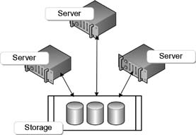
Figure 15.9 Fibre Channel point-to-point topology.
Fibre Channel Arbitrated Loop
Using a shared loop, this implementation is similar to the token ring topology with the physical arrangement of a star. FC-AL must arbitrate for its attention, with the highest priority winning. Only a single device can perform I/O operations on the loop at any given time. Figure 15.10 shows the FC-AL connection topology for servers and external storage.

Figure 15.10 Fibre Channel-Arbitrated Loop (FC-AL) topology.
This technology was used in the earliest implementations of FC on videoserver platforms. It worked well until it could no longer be scaled any further. A simple FC hub (not necessarily a switch) can be used to tie the devices together.
FC-AL must share the bandwidth throughout the entire loop. Data having to wait their turn while others get attention results in lower data transmission throughput.
FC-AL only allows for 8-bit addressing and supports not more than 127 devices on a loop. Adding or removing a device results in having to reinitialize the loop, which disrupts data traffic until completed.
Fibre Channel Switched Fabric
Abandoning the loop and point-to-point limitations required the creation of what has become the primary reason for utilizing Fibre Channel in SANs. A FC switched fabric network (see Fig. 15.11) provides for dedicated bandwidth allocation and a high degree of scalability. The fabric is a logical space where all nodes can communicate among each other in the network. This space can be created with a single switch or a network of switches.
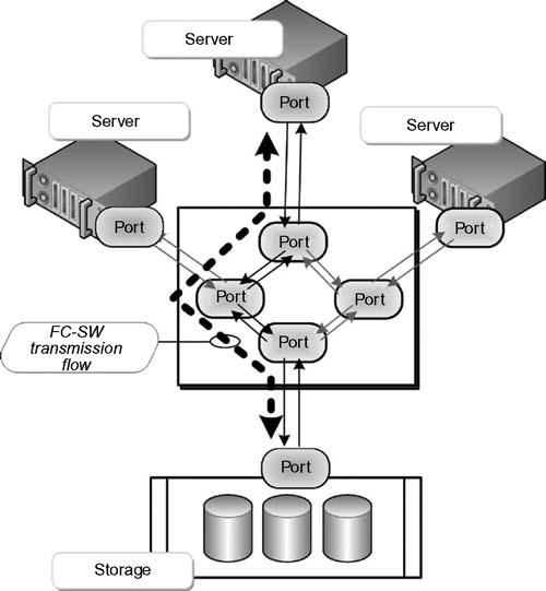
Figure 15.11 Fibre Channel Switched Fabric (FC-SW) with one transmission path shown.
As part of the fabric addressing scheme in a FC-SW environment, each switch is provided a unique domain identifier. The nodes in a switched fabric do not share a loop, but data is transferred through dedicated node paths.
The intelligence in a FC-SW topology is significant. The switch handles the data traffic (frame routing) from an initiator node to a target node directly through its switch ports. Using the same log-in procedures, traffic can be isolated from other node paths, thus preventing latencies in delivering data to the other ports.
Zoning
A switch function in FC, zoning enables the logical segmentation of nodes within the fabric. Through the log-in procedures, when a host device or storage array logs into the fabric, it becomes registered with the name server. When a port logs in, it goes through the discover process based upon those devices registered in the name server. Zoning allows only the members of the same zone to establish services as the link level.
There may be multiple zones defined in a fabric, but only a single zone can be active at a given time. Members may be associated with more than one zone and are defined in a zone hierarchy during configuration. A port or a node may be a member of more than one zone as well.
Zone sets, also known as zone configurations, are the makeup of the groupings of zones that can be enabled (activated) or disabled (deactivated) at any time by a single fabric entity. Like before, only one zone set per fabric is allowed to be active at the same time.
Naming Zones and Devices
The preferred means of naming these zones is through the 64-bit unique identifier called the World Wide Name (WWN). FC uses the World Wide Node Name (WWNN) or the World Wide Port Name (WWPN), which are assigned dynamically (unlike the FC address) in a similar fashion to how Media Access Control (MAC) addresses are used in IP networking. It is the name server in the FC environment that tracks the association of the WWNs to the dynamically assigned FC addresses for nodes.
Fibre Channel Class Support
Fibre Channel uses the term “class of service” to describe communication strategies for making connections or conveying information for a wide range of needs. Some of the classes, Classes 1–3, are routinely used in FC services; with other classes (Classes 4 and 5) not employed as often.
FC Class 1
Based on hard, circuit-switched connections where the complete path is established before data transfer begins. When a host and a device are linked, that path is not available to other hosts. Connection time is short, and this method is used for rapid, highrate high-volume data transmission.
FC Class 2
A frame-switched service does not have a dedicated connection. Delivery is guaranteed, and a receipt (or acknowledgment) is returned. If data cannot be delivered, a “busy signal” is returned, and the transmission must be retried.
An optional mode, called Intermix, can be selected. Intermix reserves the full bandwidth as a dedicated connection—but allows excess bandwidth, idle Class 1 time, to be allocated for connectionless traffic. This is an efficiency plus in Fibre Channel and maximizes the use of links for more than one class of service. This class will confirm delivery of data.
Intermix
Intermix is an option of FC Class 1 whereby FC Class 2 and FC Class 3 frames may be transmitted at times when FC Class 1 frames are not being transmitted. Both N_Ports and the fabric must support Intermix for it to be utilized.
FC Class 3
Also called datagram service, Class 3 is similar to Class 2, but is connectionless. By eliminating the requirement for confirmation of received data, delivery can be made to several devices attached to the fabric. This one-to-many form of transmission does provide notification to the sender that data has been received. If one or more of the user’s links are busy, the system cannot know to retransmit the data. Datagram delivery is not confirmed.
Delivery time for these services is a key factor in deciding which class of service to employ. When the transmission distance is a factor, and time is a key, it may be prudent to determine which service is best for the application required. This is where the final class of service, Class 4, fits in.
FC Class 4
These upper classes are less used and not as well published compared with the lower three. FC Class 4 uses virtual connections (or virtual circuits [VCs]) rather than dedicated connections. It is still a connection-oriented type of service, but Class 4 distributes the bandwidth of a port among several destinations. This class will confirm delivery.
Class 4 provides fractional bandwidth allocation of the resources of a path through a fabric that connects two N_Ports. Class 4 can be used only with the pure fabric topology. One N_Port will set up a VC by sending a request to the fabric indicating the remote N_Port as well as quality of service parameters. The resulting Class 4 circuit will consist of two unidirectional VCs between the two N_Ports. The VCs need not necessarily be at the same speed.
Like the Class 1 dedicated connection, Class 4 circuits will guarantee frames arrive in the order they were transmitted and will provide acknowledgement of delivered frames (Class 4 endto- end credit). The major difference is that an N_Port may have more than one Class 4 circuit, possibly with more than one other N_Port at the same time. In a Class 1 connection, all the resources are dedicated to the two N_Ports; however, in Class 4, the resources are divided up into potentially many circuits. The fabric in turn regulates traffic and manages buffer-to-buffer flow control for each VC separately.
FC Class 5
This class is not described in the FC-PH documents. Class 5 involves isochronous, just-in-time service and is still undefined, or may possibly be abandoned altogether.
FC Class 6
FC Class 6 provides support for multicast service through a fabric and is similar to Class 1. Procedurally, a device that needs to transmit frames to more than one N_Port at a time sets up a Class 1 dedicated connection with the multicast server within the fabric. The multicast server then sets up individual dedicated connections between the original N_Port and all the destination N_Ports. The multicast server carries the responsibility for replicating and forwarding the frame to all other N_Ports in the multicast group. N_Ports become members of a multicast group by registering with the Alias Server at the same wellknown address.
FC Class Commonalities
FC classes 1 through 3 are the three most popular in use for SANs in a Fibre Channel fabric. FC Class 1 and FC Class 4 employ fixed routing, are circuit switched, and require a setup and a tear down. FC Class 2 and FC Class 3 utilize adaptive routing, frameswitched service and may encounter routing delay and potential out-of-order delivery.
Flow Control
When a device receives data (or frames) at a rate faster than it can process them, bottlenecks occur, and failures in the transmission will happen. Flow control is intended to mitigate these problems before they occur. Without flow control, a device is forced to drop some of the frames. Fibre Channel uses a built-in flow control mechanism as its solution to this problem.
Flow control functionality works as follows: a device can transmit frames to another device only when the other device is ready to accept them. Ahead of the devices sending data to each other, they will login to each other. The login administration processes establish a “credit,” which refers to the number of frames a device can receive at a time. This value is exchanged with the other device during login, for approval and to alert both of how many frames the other can receive. As the data flow continues, and once enough frames have been transmitted, i.e.,“credit runs out,” no more frames can be transmitted until the destination device indicates it has processed one or more frames and is ready to receive new ones. The intent is to prevent any device to be overrun with frames.
Fibre Channel uses two types of flow control: buffer-to-buffer and end-to-end.
Buffer-to-Buffer
This form of flow control deals only with the link between an N_Port and an F_Port or between two N_Ports. Both ports on the link can exchange values of how many frames they are willing to receive at a time from the other port. This value becomes the other port’s BB_Credit value, which remains constant for as long as the ports are logged in. For example, when ports A and B log into each other, A may report that it is willing to handle 4 frames from B; B might report that it will accept 8 frames from A. Thus, B’s BB_Credit is set to 4, and A’s is set to 8.
Each port will keep track of the respective credit, which is called BB_Credit_CNT. It is first initialized to zero, then as each frame is transmitted, BB_Credit_CNT will be incremented by one. In return, the value is decremented by 1 for each R_RDY Primitive Signal received from the other port.
Transmission of an R_RDY indicates the port has processed a frame, freed up a received buffer, and is ready for another. Once the BB_Credit_CNT reaches BB_Credit, the port cannot transmit another frame until it receives an R_RDY.
End-to-End
End-to-end flow control is not concerned with individual links; instead, it deals with the source and destination N_Ports. While similar to buffer-to-buffer flow control, the difference is when the two N_Ports log into each other, they report how many receive buffers are available for the other port. This value becomes EE_Credit. Like buffer-to-buffer, EE_Credit_CNT is set to zero after login and increments by one for each frame transmitted to the other port. Upon reception of an ACK Link Control frame from that port, it is decremented. ACK frames can indicate that the port has received and processed one frame, N frames, or an entire sequence of frames.
Fibre Channel over Ethernet
Fibre Channel over Ethernet (FCoE) enables the convergence of Fibre Channel-based storage and Ethernet-based data traffic onto an enhanced 10-Gbit Ethernet (10 GbitE) network. FCoE is a standard of mapping of Fibre Channel frames over selected full duplex IEEE 802.3 networks and is the name given to a technology being developed (in 2010) within INCITS Technical Committee T11 as part of the FC-BB-5 (Fibre Channel Backbone) project. The mapping allows Fibre Channel to leverage 10-Gbit Ethernet networks while still preserving the Fibre Channel protocol. FCoE essentially maps Fibre Channel natively over Ethernet while being independent of the Ethernet forwarding scheme.
The FCoE protocol specification replaces the FC-0 and FC-1 layers of the Fibre Channel stack with Ethernet, and retains the native Fibre Channel constructs for a seamless integration with existing Fibre Channel networks and management software.
Those that use Ethernet for TCP/IP networks and Fibre Channel for storage area networks (SANs) now have the option of another network protocol that runs on Ethernet, alongside traditional Internet Protocol (IP) traffic. The difference with FCoE is that it runs alongside IP on Ethernet, unlike iSCSI, which runs on top of IP using TCP.
FCoE does not use IP (Layer 3) and is not routable at the IP layer, thus it will not work across routed IP networks.
FCoE requires three specific modifications to Ethernet in order to deliver the capabilities of Fibre Channel in SANs:
•Encapsulation of the native Fibre Channel frame into an Ethernet Frame
•Extensions to the Ethernet protocol to enable a lossless Ethernet fabric
•Replacing the Fibre Channel link with MAC addresses in a lossless Ethernet
The Converged Network
Computers employing FCoE now use a Converged Network Adapter (CNA), which is both a Fibre Channel host bus adapter (HBA) and an Ethernet network interface card (NIC) to the server, yet it appears as a single Ethernet NIC to the network. The CNA essentially provides a new approach to consolidation of server I/Os over a single Ethernet network, thus reducing network complexity.
With FCoE, network (IP) and storage (SAN) data traffic can essentially be consolidated with a single switch. The ability to combine Fibre Channel with 10-Gbit Ethernet (GigE), so that the the enterprise can consolidate I/O, is referred to as “unified I/O.” The value in this implementation is that it reduces the number of NICs required to connect to disparate storage and IP networks, decreases the number of cables and adapters, lowers the overall power and cooling costs, and increases utilization of the servers through server virtualization technologies.
Fibre Channel SAN Components
Up to this point in this chapter, we have looked at network storage technologies that include direct-attached storage (DAS), network-attached storage (NAS), and the roots of Fibre Channel (FC). With this background and its perspectives on applications and technology, it is time to introduce the concepts of the storage area network (SAN).
In actuality, many of the protocols upon which a FC-SAN is built were covered in the previous sections on Fibre Channel. To paraphrase again, a storage area network is provisioned to use Fibre Channel switches to carry (transmit and receive) data between servers (or hosts) and storage devices. The SAN provides the roadmap for the consolidation of storage by allowing it to be shared across multiple servers and across other networks.
Fibre Channel storage area networks use Fibre Channel exclusively for the transport of the commands, data, and status information. Originally, the SAN was implemented on a local basis and to a relatively discrete set of servers and storage systems. Many were purpose built to serve a particular storage requirement, to extend bandwidth on a platform, or as a specific solution to a sprawl of computers, servers, and islands of storage that collectively drew down on the overall computer power of the system as a whole.
These early systems would use a hub as the center of the spokes connecting storage and servers together. Those applications utilitzed less costly peripheral products, such as fabric switches, and for many satisfied the requirements of adding capacity and increasing bandwidth simultaneously. Videoserver platforms that began looking at external storage quickly jumped on the Fibre Channel bandwagon.
Elements of the SAN
Three fundamental components make up the SAN at its highest level (see Fig. 15.12):
•Network infrastructure
•Servers
•Storage
Another level of granularity of components for the SAN breaks these primary components down slightly further into:
•storage arrays
•cabling (copper or fiber optic)
•node ports
•software (for the management of the SAN)
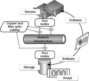
Figure 15.12 Elements of a SAN.
Storage systems may include intelligent storage systems (discussed in a later chapter); arrays comprised of disks in RAID configuration and specifically Fibre Channel disk drives that primarily employ SCSI protocols; tape library or virtual tape library (VTL) storage systems; or a combination of some or all of these elements.
Management software are both those embedded into the FC switches, nodes, and storage systems; and those loaded onto the host devices that support the applications through terminals that can configure and manage the data flow parameters. This software will further control the logical partitioning, called zoning, described earlier. This software also provides for the management of the HBAs, storage components, and associated interconnecting devices or subsystems.
Topologies or Architectures
A defining element of the SAN is its “topology” through which the SAN connects to devices on the network. The word “architecture” is also tightly coupled with the topology. Much like the term when it is applied to buildings, the “architecture” of any system is comprised principally of a formal description that defines the properties of that system, and how it “appears” to the other associated elements within that system.
Topology is a somewhat more ambiguous term depending upon what it refers to and in what context it is placed. A topology might be expressed as a layout or pattern of interconnections for various elements within a system, typically in this discussion, a network. It may be virtual, physical, or structural. Although it is a graphical map of the connectivity of a network, while it describes how the cables are connected to devices, it lacks in defining the functionality of how those devices interact or influence one another.
Topologies may be both physical and logical, and they may be identical or indifferent to each other on that same network. This chapter has already discussed the topologies of a networked storage system, in terms of switches, for example if the system is point-to-point connected, if it is on a switched architecture, and the like.
Homogeneous or Heterogeneous
Often used to describe storage and storage networking environments, homogenous is an environment where the components are provided by the same vendor directly or via a partner relationship. Heterogeneous is a mixture of technologies from multiple vendors, provided as an environment with interoperable components. For example, a heterogeneous SAN would likely include switches running in interoperability mode.
The homogenous environment will most likely be a proprietary or vendor-specific implementation where all the system components are provided by a single company that makes all the elements under their own brand (e.g., Brocade, Cisco, or QLogic SAN). A storage vendor-specific SAN that pairs switches and adapters from a partner with specific storage solutions would be another example of a homogeneous design.
Even though another vendor may use the same partner switches and adapters, the storage vendor might not provide support for that certain other vendors’ storage—thus, this becomes a heterogeneous “storage environment.”
Prominent Fibre Channel Topologies
At this juncture, we will focus attention on the more prominent topologies in Fibre Channel: island, mesh, collated, and coreedge fabric. Although each topology serves a particular niche, of the groups described, core-edge fabric is the most scalable and widely deployed in SAN implementations.
Designing any scale of a SAN core-edge fabric can be a complicated process. A Fibre Channel SAN may consist mainly of an individual fabric or multiple sets of fabrics that are connected through a FC routing function. At an enterprise level such a SAN might have the architectural look shown in Figure 15.13.
Island SAN
When the SAN exists as a discrete, isolated entity within a larger SAN, it is called an “island SAN.” The components are usually located all within the same building or a single room.

Figure 15.13 A complete storage area network (SAN) schematic.
SAN islands will typically evolve as the organization grows. When a large SAN consists of several islands, those individual islands may be interconnected and are enabled so as to share data collectively. There are several ways in which SAN island interconnection can be accomplished, although they each carry their own challenges (see Fig. 15.14).
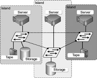
Figure 15.14 Three SAN islands set into a meshed SAN.
Even though a SAN island may be physically located to a specific site, it may be used for many applications, by more than a single department within that organization, or by multiple organizations within the enterprise. If necessary, an administrator may elect to allocate all of a SAN island’s resources to a single critical application.
Drive sharing and data copying are a common activity among SAN islands. Data redundancy, where important files or folders are duplicated, and then contained on multiple SAN islands, is not uncommon.
Island SANs that are connected together through inter-switch links (ISLs) become a “meshed SAN.” The drawback is when interconnecting these smaller switches into a meshed fabric, the number of required ISLs quickly grows per the number of included switches. This limits the number of ports available on the fabric.
Collocated SAN
When the approach blends storage devices and host connections on the edge switches while keeping paired devices as close together as possible, this is referred to as a “collocated SAN.” With this structure, as depicted in Figure 15.15, scalability is much like that of a pure core-edge design. In a collocated SAN, none of the devices are placed on the core; in turn, this allows for much better performance since the resources are kept close to their users.
Over the long term, the maintenance of a collocated SAN grows in difficulty. Edge switches are not usually expandable. To allow for future growth, ports on every edge will need to be reserved, burdening the size of the switches from the first level of implementation. As time goes on, connections to devices that are distant from its user tend to stay put for the long term. This inherently reintroduces latency and ISL congestion concerns that the collocated design concept was supposed to mitigate.

Figure 15.15 A collocated SAN using four FC switches and inter-switch links (ISL) to connect to a single director.
A real benefit of a collocated design is that SAN islands are already collocated. Adding a director to interconnect the outlying fabrics instantly transforms it into a collocated SAN.
Fabric Protection
An element that is critical to any design and should always be in place is that of dual redundant fabrics. At the enterprise level, an interconnected SAN is the seawall around the entire organization’s data. Should an island SAN sink, it then only takes out a few applications. One method to protect the enterprise from a complete collapse is to implement two mirrorimage fabrics and connect every host and storage system to each. Pathing software is then used to maintain connectivity should one SAN fails.
Even though virtual SAN technologies provide extra protection from a fabric failure, never rely on a single piece of hardware to provide both paths; instead separate the fabrics with a physical “air-gap” between the two.
Core-Edge
Usually comprised of switches, this is a relatively inexpensive means to add more hosts in a fabric. Best practice core-edge SAN designs can be built out gradually over time. Such a design is allowed to evolve from a chain of isolated SAN islands to a completely unified, large-scale SAN (see Fig. 15.16).
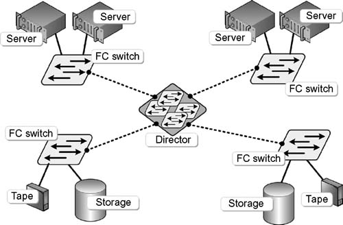
Figure 15.16 A core-edge SAN configuration.
Scaling the SAN
It goes without saying, again, that growth is inevitable. Going back to the well for new equipment, especially those intangible items that accountants see little to no ROI from, is a task most of us do not enjoy going through. Careful planning and the appropriate reuse of components can make scaling for the future a productive process.
Most sites would not have the luxury of director-class hardware, so determining where to relocate the current switches into a new topology can be remedied by having those legacy switches become the edge switches in the new environment. One of the front end postures you should take includes upgrading to newer switches if you have products that are more than a year old. If you are currently using FC hubs, for example in an arbitrated loop (FC-AL), and you do not need that kind of connectivity, this would be a good time to retire them.
Avoid heterogeneous SANs. Pick a single vendor for the new SAN, and swap out other equipment where appropriate.
Be sure to understand, and evaluate, the compatibility of firmware revisions running on the new (and existing) switches being consolidated. There may be special compatibility mode settings necessary to make the different switch types work together.
To avoid SAN segmentation, make sure the identifiers (such as domain IDs and zone names) are unique on all the switches. Implementing a segregated core-edge design requires that the storage and servers be reconnected to their respective sides of the director. Collocated SANs will require little reconnection; however, port reservation for the future is a necessity for growth.
Next Generation SANs
In the following chapter, the concepts of intelligent storage will be developed. The advancements since the introduction of 1 Gbit/second Fibre Channel have extended well into the 8 Gbits/ second range and are headed toward 16 Gbits/second; with expectations far beyond that. However, the increased development of Ethernet added to the other advancements such as Fibre Channel over Ethernet, Fiber Channel over IP, and other converged network infrastructures brings another added dimension to storage at a network level.
Further Readings
Gupta, M. (2002). Storage Area Network fundamentals. Cisco Press.
Thornburgh, R. H., & Schoenborn, B. J. (2001). Storage Area Networks — designing and implementing a mass storage system. Hewlett-Packard Professional Books.
InterNational Committee for Information Technology Standards (INCITS) on storage, and their associated Technical Committees (TC):
http://www.incits.org/
T10 — SCSI Storage Interfaces technical committee
T11 — Fibre Channel Interfaces technical committee
T13 — ATA Storage Interfaces technical committee
Fibre Channel Industry Association.
http://www.fibrechannel.org/
Storage Networking Industry Association.
http://www.snia.org