
10
IP STORAGE
Block data storage has been driven by user demand and the vendors who have continued to find new efficiencies in storage data networking. The goals for developing and implementing IP storage networking are directed by the aim to reduce the costs associated with acquisition, administration, and support.
The migration away from fixed dedicated networking infrastructures that are supported over high speed Gigabit Ethernet is being achieved by employing protocols centered on IP, such as iSCSI, iFCP, and FCIP, to moving block data. This chapter looks at these various types of storage subsystems and devices that define the future of storage on IP networks.
KEY CHAPTER POINTS
•Internet protocol in a connected or connectionless environment, and the basics of IP-addressing, domain naming, and Ethernet
•Storage that is connected over IP networks as IP storage (IPS)
•Defining and detailing IP networking: iSCSI, iFCP, FCIP, iSNS
•QoS for IP storage networks, RSVP, MPLS, InfiniBand
•Security and other considerations for implementing storage over IP networks
Internet Protocol
In complex networks, dynamic routing is enabled by using Internet Protocol (IP). By taking advantage of IP, storage can be extended over the network, and through the use of the protocols we will be discussing, it becomes an alternate means for moving the block data of the network.
We will start the discussion on IP storage with a brief overview and review of the fundamentals, including the protocols, definitions, and standards associated with this technology.
Delivering Packets by IP
Data can be sent between one computer and another over the Internet through IP. The Internet is essentially the interconnection of many individual networks. The Internet Protocol is the governing set of rules that allows one network to communicate with any other network. When configured for broadcast messages, this communication could be sent to all the other networks with like and proper configurations.
In this example model, each host computer on the Internet will have at least one IP address that uniquely identifies it from other computers on the Internet. When data are sent or received using this protocol, the message will be divided into small chunks of data called “packets.” The sender’s Internet address and the receiver’s address are included in each packet.
Each network needs to know its own address on the Internet and the address of any other networks with which it communicates. To be part of the Internet, an organization needs an Internet network number, which can be requested from the Network Information Center (NIC). The unique network number is then included in any packet that is sent out of the network onto the Internet.
Typically, the packet is first sent to a gateway (i.e., a computer) that knows about a small portion of the Internet. The gateway reads the packet, discovers the destination address, and forwards the packet to an adjacent gateway that then reads that destination address and forwards it the next. The process continues across the Internet until one of the gateways recognizes that the packet does belong to a computer within its immediate neighborhood, also known as a domain. At this point, the gateway forwards that packet directly to the computer whose address was specified originally from the host or sending computer.
Messages are usually divided into a number of individual small sizes, the packets, so that if necessary the packets may take different routes to get to the destination domain (neighborhood). This causes the packets to arrive in a different order than they were sent in. In this model, IP’s responsibility is to just deliver them to the right address. Transmission Control Protocol (TCP), another very familiar protocol, is charged with reordering and reassembling the randomly delivered packets into the proper order.
Connected or Connectionless
In the Open Systems Interconnection (OSI) communication model, IP is in Layer 3, known as the Networking Layer. IP is called a “connectionless” protocol. There is no continuous connection between any of the points that are communicating. As packets traverse the Internet, each of them is treated as an independent unit of data with no relationship to any other unit of data that is also on this vast highway.
Transmission Control Protocol (TCP), which is a connectionoriented protocol that was standardized in 1981 in RFC 793, is the instrument that keeps track of the packet sequence in a message.
Internet Protocol Version 4 (IPv4) is the most widely used version of IP today. When engineered, IPv4 was thought to possess all the addresses and space ever imagined for use on the Internet. This, however, was not the case, so IP Version 6 (IPv6) was developed to create much longer addresses and in turn, the possibility of many more Internet users. IPv6 includes the capabilities of IPv4. Any server that is capable of supporting IPv6 packets is by definition also able to support IPv4 packets.
IP Address Classes
Since networks will vary in size, four different address formats called “classes” are used. In IPv4, an IP address will usually be expressed as four decimal numbers, each representing eight bits, separated by periods. This is sometimes known as the “dot address” or “dotted quad notation.”
•Class A addresses are for large networks with many devices (represented as “network.network.network.local”).
•Class B addresses are for medium-sized networks.
•Class C addresses are for small networks (fewer than 256 devices) (represented as “network.network.network.local”).
•Class D addresses are multicast addresses.
The number version of the IP address can be (and usually is) represented by a name or series of names called the domain name.
Addresses
In addition to the network address, information is needed about which specific machine or host in a network is sending or receiving a message. Thus, an IP address needs both its unique network address, and a host number, which would be unique within the network. The host number is sometimes referred to as a local or machine address.
Part of the local address can identify a subnetwork (i.e., a subnet address), which allows a network to be subdivided into several physical subnetworks. In this mode, there might be several different local area networks that are configured to handle many devices.
Domain Naming
The system that locates an entity (e.g., a commercial, educational, or non-profit organization) on the Internet is built around the concept of a “domain name.” The familiar Web annotation uses three basic segmentations for this system.
When the location is described as
this locates an Internet address for “mydomainname.com” at an Internet point 199.0.0.5. It is served by a particular host server that is named “www” (World Wide Web). The last part of the domain name, in our example “.com,” reflects the organization or entity’s purpose, and is called the “top-level” domain name. For example, “.com” stands for commercial; “.edu” for education; “.org” for organization, etc. This nomenclature is assigned when a user applies for and registers their particular domain name.
The “mydomainname” part of the domain name, together with the top-level portion, is called the “second-level” domain name. This second-level domain name is a human-readable representation of the actual Internet address that it maps to. Second-level domain names must be unique on the Internet. They are registered with one of the ICANN-accredited registrars for the COM, NET, and ORG top-level domains. Additional top- level domains include “.tv”, or if they are non- USA based, they may be geographically associated with the country they are registered to, for example, “.ca” is for Canada, “.it” is for Italy, etc.
The third level defines a particular host server at the Internet address. In this example, “www” is the name of the server that handles Internet requests (note that a second server could be annotated as “www2.” The third level of domain name is not required; as such a fully qualified domain name could have been simply “mydomainname.com” (the server is then assumed).
The nomenclatures allow for additional “subdomain” levels to be used. If desired, one could employ the domain name
“www.yoursubdomainname.mydomainname.com.”
The Uniform Resource Locator (URL), on the Web, is that part of the domain addressing scheme that tells a domain name server using the domain name system (DNS) where (or if) a request for a given Web page is to be forwarded. The domain name is therefore mapped to an IP address representing a physical point on the Internet.
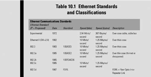
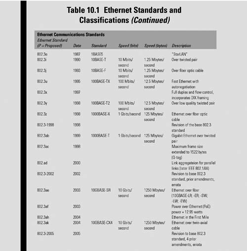
Ethernet
A widely installed local area network (LAN) technology, Ethernet is standardized under the IEEE 802.3 specifications. Gigabit Ethernet is standardized in IEEE 802.3z, with 10 Gbit Ethernet in IEEE 802.3a. The IP-related standards are managed under the auspices of the Internet Engineering Task Force (IETF) through the process of Requests for Comments (RFCs) that handle a growing range of diverse topics, including protocols and management issues.
Ethernet was originally developed by Xerox from an earlier specification called Alohanet (for the Palo Alto Research Center Aloha network) and then developed further by Xerox, DEC, and Intel. Ethernet was named by one of its developers, Robert Metcalfe, for the passive substance called “luminiferous ether,” which was once thought to pervade the universe, carrying light throughout. Table 10.1 shows the progress of Ethernet standards from 1972 through the proposed additions (prefaced with the “P”) anticipated for adoption in 2011.
Devices, ranging from hosts to switches, are connected to the local area network (LAN) through special grades of twisted pair cable, syntactically called “category” cabling. Cabling categories are numbered according to the data speed and performance characteristics specified for the bitrates they will carry.

Their host or device signals, when connected, then compete for access to the network using a Carrier Sense Multiple Access with Collision Detection (CSMA/CD) protocol.
Internet Engineering Task Force
The Internet Engineering Task Force (IETF) is the open international community of network designers, operators, vendors, and researchers supporting the evolution and smooth operation of the Internet, whose Mission Statement is documented in RFC 3935.
IETF Working Groups are divided into areas that are managed by area directors (ADs), who are members of the Internet Engineering Steering Group (IESG). Architectural oversight is provided by the Internet Architecture Board (IAB), which also adjudicates appeals when complaints are received that the IESG has failed. The IAB and IESG are chartered by the Internet Society (ISOC).
The Internet Assigned Numbers Authority (IANA), also chartered by the ISOC, is the central coordinator, responsible for the assignment of unique parameter values for Internet protocols. IANA acts as the clearinghouse in the assignment and coordination of the uses for numerous Internet protocol parameters.
The IETF holds meetings three times a year, with the bulk of its work conducted via other electronic means. The IETF has eight functioning areas related to technology development and standards:
•Applications
•Internet
•Operations and Management
•Routing
•Security
•Sub-IP
•Transport
•User Services
Inside this structure, the IETF working group on “Internet Protocol Storage (IPS),” aimed at studying IP storage, was formed.
IP Storage
Significant interest in using IP-based networks to transport block storage traffic began around the end of 2000. The initiatives for IP storage evolved on a foundation of previously established IEEE 802.3 Ethernet standards and the IP-related standards from the diverse Request for Comments (RFCs) of the IETF. These two industry standards, IP and Ethernet, only describe a part of the equation for network storage on IP.
IP storage needed to accommodate the earlier recognized standards for SCSI and for Fibre Channel storage devices. The principle entities responsible for these standards were under the purview of the INCITS (formerly NCITS) Committees:
•INCITS T10 for SCSI
•INCITS T10 for Fibre Channel Protocol (FCP)
•INCITS T11 for Fibre Channel transport
The IP Storage Working Group was a chartered group tasked with developing a protocol to transport the Small Computer Systems Interface (SCSI) protocol over the Internet. The iSCSI protocol defines a mapping of SCSI transport protocol over TCP/IP so that SCSI storage controllers (principally disk and tape arrays and libraries) can be attached to IP networks (notably Gigabit Ethernet and 10 Gbit Ethernet).
The IP Storage Working Group functioned from September 25, 2000, through November 1, 2007, pursuing a pragmatic approach to the encapsulation of existing protocols, (e.g., SCSI and Fibre Channel), into a set of IP-based transport or transports. The group further focused on related issues (e.g., security, naming, discovery, and configuration), as opposed to modifying existing protocols.
The working group also considered whether a layered architecture providing common transport, security, and/or other functionality for its encapsulations was the best technical approach.
The following sections will begin to focus on the approaches and implementations that emerged from the 7-year efforts of the IP Storage Working Group.
iSCSI
The family of protocols most associated with communicating between I/O devices, especially storage systems, is the Small Computer Systems Interface (SCSI). SCSI is a client-server architecture. The clients of a SCSI interface are called “initiators.” Initiators issue SCSI commands to request services from components, and logical units of a server known as “targets.”
A “SCSI transport” maps the client-server SCSI protocol to a specific interconnect. An initiator is one endpoint of a SCSI transport and a target is the other endpoint. The SCSI protocol has been mapped over various transports, including parallel SCSI, IPI, IEEE-1394 (FireWire), and Fibre Channel (FC). These transports are I/O specific with limited and designated distance capabilities.
The iSCSI protocol is a means of transporting SCSI packets over TCP/IP, providing for an interoperable solution that can take advantage of existing Internet infrastructure, Internet management facilities, and address distance limitations. The iSCSI protocol aims to be fully compliant with the standardized SCSI Architecture Model (SAM).
iSCSI RFCs
In recent times, study groups inside the IETF have been working towards a consolidation of several RFCs into a single document that combines certain groups and makes additional updates to the specification of others. The iSCSI documents included in this effort include
•RFC 3720, which defined the original iSCSI protocol.
•RFC 3721, which discusses iSCSI naming examples and discovery techniques.
•RFC 3980, which added an additional naming format to iSCSI protocol.
•RFC 4850, which followed up by adding a new public extension key to iSCSI.
•RFC 5048, which offered a number of clarifications and a few improvements and corrections to the original iSCSI protocol.
This consolidation will supersede the text found in RFCs 3720, 3980, 4850, and 5048, placing them into a single document; and it makes additional updates to the consolidated specification, which will include a further update to the naming and discovery techniques cited in RFC 3721.
iSCSI Protocol
The iSCSI protocol is a mapping of the SCSI command, event, and task management model over the TCP protocol. SCSI commands are carried by iSCSI requests. SCSI responses and status are carried by iSCSI responses. iSCSI also uses the request response mechanism for iSCSI protocol mechanisms.
Initiator—Target Messages
The terms “initiator” and “target” refer to “iSCSI initiator node” and “iSCSI target node,” respectively, unless otherwise qualified. In keeping with similar protocols, the initiator and target divide their communications into messages. This consolidated document uses the term “iSCSI protocol data unit” (iSCSI PDU) for these messages.
For performance reasons, iSCSI allows a “phase-collapse.” A command and its associated data may be shipped together from initiator to target, and data and responses may be shipped together from targets.
Transfer Directions
The iSCSI transfer direction is defined with respect to the initiator. Outbound or outgoing transfers are transfers from an initiator to a target, while inbound or incoming transfers are from a target to an initiator.
An iSCSI task is an iSCSI request for which a response is expected. In the consolidation document “iSCSI request,” “iSCSI command,” request, or (unqualified) command have the same meaning. Furthermore, unless otherwise specified, status, response, or numbered response have the same meaning.
Network Address Authority (NAA)
The INCITS T11 Framing and Signaling Specification [FC-FS] defines a format called the Network Address Authority (NAA) format for constructing worldwide unique identifiers that use various identifier registration authorities. This identifier format is used by the Fibre Channel and SAS SCSI transport protocols. As FC and SAS constitute a large fraction of networked SCSI ports, the NAA format is a widely used format for SCSI transports. The objective behind iSCSI supporting a direct representation of an NAA-format name is to facilitate construction of a target device name that translates easily across multiple namespaces for a SCSI storage device containing ports served by different transports. More specifically, this format allows implementations wherein one NAA identifier can be assigned as the basis for the SCSI device name for a SCSI target with both SAS ports and iSCSI ports.
The iSCSI NAA naming format is “naa” plus a “.” (dot), followed by an NAA identifier represented in ASCII- encoded hexadecimal digits, as shown in Fig. 10.1.

Figure 10.1 NAA identifier types in 64-bit and 128-bit ASCII-encoded hexadecimal notation
iFCP
Fibre Channel is a frame-based, serial technology designed to promote peer-to-peer communication between devices at gigabit speeds with low overhead and minimal latency. To successfully implement and integrate the advantages found in Fibre Channel, especially when the physical or geographic separation between nodes or systems exceeds the distance specifications of the Fibre Channel standards, alternative provisions have been designed to provide a more universal solution for new and existing systems. Some of these alternative and supplemental protocols are described in the following sections of this chapter. Most of these solutions are bundled under the heading of TCP/IP-based networks.
Chapter 6 also provides an extensive look into Fibre Channel and storage area networking.
Gateway Protocol to TCP/IP
Internet Fibre Channel Protocol (iFCP) is a gateway-to-gateway protocol for the implementation of Fibre Channel fabric functionality over a TCP/IP network. The iFCP protocol standard was developed by the IETF per RCC 4172 (September 2005). Its functionality is provided through TCP protocols for Fibre Channel frame transport via the distributed fabric services specified by the Fibre Channel standards. The iFCP architecture enables internetworking of Fibre Channel devices through gatewayaccessed regions with the fault isolation properties of autonomous systems and the scalability of the IP network.
Provisions
iFCP uses TCP to provide congestion control, error detection, and recovery. iFCP’s primary objective is to allow for the interconnection and networking of existing Fibre Channel devices, at wire speeds, over an IP network. The protocol, and its method of frame address translation, permit the attachment of Fibre Channel storage devices to an IP-based fabric through transparent gateways. The protocol achieves transparency by allowing normal Fibre Channel frame traffic to pass directly through the gateway with provisions (where necessary) for intercepting and emulating the fabric services required by a Fibre Channel device.
Fabric
The iFCP protocol enables the implementation of Fibre Channel fabric functionality on an IP network in which IP components and technology replace the Fibre Channel switching and routing infrastructure. The example of Fig. 10.2 shows a Fibre Channel network with attached devices. Each device accesses the network through an N_PORT (node port) that is connected to an interface whose behavior is specified in FC fabric switch (FC-FS) or FC arbitrated loop (FCAL2). In this case, the N_PORT represents any of the variants described; with the interface to the fabric able to be an L_PORT, F_PORT, or FL_PORT.
Within the Fibre Channel device domain, addressable entities consist of other N_PORTs and Fibre Channel devices internal to the network that perform the fabric services defined in Fibre Channel General Services-3 (FC-GS3).
One example of an equivalent iFCP fabric is shown in Fig. 10.3. The fabric consists of two gateway regions, each accessed by a single iFCP gateway.

Figure 10.2 An example of a Fibre Channel network
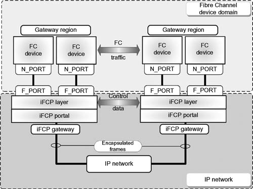
Figure 10.3 Example of an iFCP fabric with its interface to an IP network.
Each gateway contains two standards-compliant F_PORTs and an iFCP Portal for attachment to the IP network. Fibre Channel devices in the region are those locally connected to the iFCP fabric through the gateway fabric ports.
Looking into the fabric port, the gateway appears as a Fibre Channel switch element. At this interface, remote N_PORTs are presented as fabric-attached devices. Conversely, on the IP network side, the gateway presents each locally connected N_PORT as a logical Fibre Channel device.
iFCP Services
The main function of the iFCP protocol layer is to transport Fibre Channel frame images between locally and remotely attached N_PORTs.
Transport Services
When transporting frames to a remote N_PORT, the iFCP layer encapsulates and routes the Fibre Channel frames comprising each Fibre Channel Information Unit via a predetermined TCP connection for transport across the IP network.
When receiving Fibre Channel frame images from the IP network, the iFCP layer de-encapsulates and delivers each frame to the appropriate N_PORT.
Other
The iFCP protocols provide for other services and models, which are detailed in RFC 4172 (Section 5 onwards). Some of those additional services and models include
•iFCP support for link services and messaging
•TCP transport of iFCP frames
•iFCP Session Model
•iFCP Session Management
•Fibre Channel Frame Encapsulation/De-Encapsulation
•Fibre Channel Broadcast and Session Management
Security
The iFCP protocol is designed for use by gateway devices deployed in enterprise-class data centers. These environments characteristically have security gateways aimed at providing network security through a high degree of isolation from public networks. Nonetheless, iFCP data may need to traverse security gateways in order to support SAN-to-SAN connectivity across those public networks.
iFCP relies upon the IPSec protocol suite to provide data confidentiality and authentication services. iFCP relies upon Internet Key Exchange (IKE) as the key management protocol. Detailed considerations for use of IPsec and IKE with the iFCP protocol can be found in [SECIPS].
iFCPs communicate across gateways, and as such are subjected to unwanted attacks. These adversarial threats may include attempts to
•acquire confidential data and identities by snooping data packets,
•modify packets containing iFCP data and control messages,
•inject new packets into the iFCP session,
•hijack the TCP connection carrying the iFCP session,
•launch denial-of-service (DOS) attacks against the iFCP gateway,
•disrupt the security negotiation process,
•impersonate a legitimate security gateway, or
•compromise communication with the iSNS server.
iFCP gateway administration must be prepared to thwart these attacks by implementing and confidentially using (through per-packet encryption) data origin authentication, integrity, and replay protection on a per-datagram basis. Because iFCP is a peer-to-peer protocol, the iFCP gateway must implement bidirectional authentication of the communication endpoints and be prepared to use them. Administrators must implement and enable the use of a scalable approach to key management.
Other security related practices should include
•Authorization or authentication
•Policy control
•iSNS (discussed later in this chapter)
•Other applicable technologies from IPsec and IKE per recommendations in RFC 4171, Section 10.3.1 “Enabling Technologies.”
The next section discusses the mechanisms for LAN, WAN, and MAN connectivity useful in interconnecting Fibre Channel SAN islands over an IP network.
Fibre Channel over IP (FCIP)
Fibre Channel over TCP/IP (FCIP) describes mechanisms that provide for the interconnection of islands of Fibre Channel storage area networks over IP-based networks to form a unified storage area network in a single Fibre Channel fabric. FCIP enables the transmission of Fibre Channel (FC) information by tunneling data between storage area network (SAN) facilities over IP networks. IP-based network services offer connectivity between the SAN islands over LANs, MANs, or WANs. Figure 10.4 shows the FCIP stack and its relationship to other protocols.
FCIP may be found annotated as FC/IP, while also being called “Fibre Channel tunneling” or “Fibre Channel storage tunneling.” This storage networking technology was developed by the IETF and is defined in RFC 3821 (July 2004). These mechanisms are an important technology for linking Fibre Channel SANs.
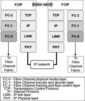
Figure 10.4 The “FCIP Protocol Stack Model” showing the relationship between FCIP and other protocols.
Complementary
FCIP and iSCSI are complementary solutions that are typically used for different purposes. FCIP transparently interconnects Fibre Channel (FC) SAN islands over IP networks, while iSCSI allows IP-connected hosts to access iSCSI or FC-connected storage.
With FCIP, Fibre Channel frames are encapsulated in IP so that both SCSI and non-SCSI frames can be transported over an IP network. With iSCSI, SCSI commands and data frames are encapsulated in IP to support I/O disk access over an IP network.
By combining FCIP and iSCSI, enterprises are able to:
•Interconnect SAN islands.
•Provide applications including remote backup and replication, while performing Fibre Channel I/O communication.
Nominal Distances
Fibre Channel standards have elected to use nominal distances between switch elements that are less than the distances available in an IP network. Since Fibre Channel and IP-networking technologies are compatible, it is reasonable to turn to IP networking as a medium for extending the allowable distances between Fibre Channel switch elements.
One fundamental assumption made in the FCIP specification is that the Fibre Channel traffic is carried over the IP network in such a manner that the Fibre Channel fabric and all Fibre Channel devices on the fabric are “unaware of the presence of the IP network.” As such, FC datagrams need to be delivered in such time as to comply with existing Fibre Channel specifications.
FCIP Link
The FCIP Link (Fig. 10.5) is the basic unit of service provided by the FCIP protocol to an FC fabric. An FCIP link connects two portions of an FC fabric using an IP network as a transport to form a single FC fabric.

Figure 10.5 FCIP Link model.
At the points where the ends of the FCIP Link meet portions of the FC fabric, an FCIP Entity combines with an FC Entity to serve as the interface between FC and IP. In an implementation that tunnels an FC fabric through an IP network, it is necessary to combine an FC Entity with an FCIP Entity in order to form a complete interface between the FC fabric and IP network. An FC Fabric may contain multiple instances of the FC/FCIP Entity pair shown on either side of Fig. 10.6.

Figure 10.6 Model for two connected FC/FCIP Entity pairs.
An FCIP Link shall contain at least one TCP connection, and it may contain more than one TCP connection. The endpoints of a single TCP connection are FCIP Data Engines (see Fig. 10.7), with the endpoints of a single FCIP Link being FCIP Link Endpoints (FCIP_LEP).

Figure 10.7 Fibre Channel over IP Link Endpoint (FCIP_LEP) model.
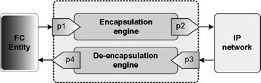
Figure 10.8 Fibre Channel over IP Data Engine (FCIP_DE) model.
An FCIP_LEP is a transparent data translation point between an FC Entity and an IP network. A pair of FCIP_LEPs communicating over one or more TCP connections create an FCIP Link to join two islands of an FC fabric, producing a single FC fabric (Fig. 10.8). The FCIP Data Engine (FCIP_DE) is a combination dual bidirectional encapsulation/de-encapsulation device through which data enter and leave through a set of four portals. The portals are not required to examine or process the data that traverse them.
Clarification
It is easy to get this (FCIP) and the previously described iFCP confused, given the order and similarities of the two acronyms. One should understand that FCIP simply extends existing Fibre Channel fabrics through the medium of an IP network. In FCIP, TCP/IP is used only to traverse a metro or wide area distance.
By comparison, iFCP is a migration strategy from current Fibre Channel SANs to future IP-based SANs. The gateways of iFCP can either complement existing FC fabrics, or they may replace them entirely, while still leveraging the substantial investments that had been made in an existing Fibre Channel storage architecture.
Since iFCP enables customers to build IP SAN fabrics, it becomes a convenient means to migrate to a mixed Fibre Channel/iSCSI environment. Furthermore, iFCP will potentially offer users a channel to minimize the Fibre Channel fabric component and maximize the use of their legacy TCP/IP infrastructure.
Internet Storage Name Service (iSNS)
Used for interaction between Internet Storage Name Service (iSNS) servers and iSNS clients, this protocol facilitates automated discovery, management, and configuration of iSCSI and Fibre Channel devices (using iFCP gateways) on a TCP/IP network. iSNS provides for intelligent storage discovery and management of services comparable to those found in Fibre Channel networks. The goal is to allow for a commodity IP network to function in a capacity similar to that of a storage area network (SAN).
iSNS facilitates a seamless integration of IP and Fibre Channel networks through its capabilities of emulating Fibre Channel fabric services, and through the management of both iSCSI and Fibre Channel devices (using iFCP gateways). Internet Storage Name Service provides added merit to any storage network comprised of iSCSI devices and iFCP gateways addressing Fibre Channel devices, or any combination thereof.
Standards-compliant iSNS implementations are required to support the iFCP protocol; however, supporting the iSCSI protocol is optional.
iSNS Architectural Components
The set of components that make up the iSNS architecture, per RFC 4171, adopted in September 2005, include the following components consisting of the iSNS protocol, its client, servers and database.
iSNS Protocol (iSNSP)
A lightweight and flexible protocol that specifies how iSNS clients and servers communicate. The protocol is appropriate for various platforms, including switches, targets, and server hosts.
iSNS Client
These initiate transactions with iSNS servers using the iSNS Protocol (iSNSP). iSNS clients are processes that are co-resident in the storage device. They can register device attribute information, download information about other registered clients in a common discovery domain (DD), and receive asynchronous notification of events that occur in their DD(s). A special type of iSNS client, called a management station, will have access to all DDs stored in the iSNS.
Management Station
A management station will use iSNS to monitor storage devices and to enable or disable storage sessions by configuring discovery domains, usually interacting with the iSNS server as a control node endowed with access to all iSNS database records and with special privileges to configure discovery domains. Through manipulation of the discovery domains, management stations control the extent of device discovery for iSNS clients querying the iSNS server. The management station may use proprietary protocols or SNMP-based solutions to cross reference, report on different segments of the enterprise network, or transfer device records between the iSNS servers.
iSNS servers
These servers will respond to iSNS protocol queries and requests. They will initiate iSNS protocol state change notifications (SCNs). The properly authenticated information submitted by a registration request is stored in an iSNS database.
State Change Notification (SCN)
SCN is a service that allows the iSNS server to issue notifications about network events affecting the operational state of storage nodes. The iSNS client may register for notifications on behalf of its storage nodes for notification of events detected by the iSNS server. SCNs notify iSNS clients of explicit or implicit changes to the iSNS database. The connectivity state of peer storage devices in the network are not necessarily indicated by the service. The storage device’s response to receipt of a state change notification is determined by the type of implementation of these services.
SCN Registrations
Two types of SCN registrations are possible: regular registrations and management registrations. A regular SCN registration indicates that the Discovery Domain Service shall be used to control the distribution of SCN messages. Regular SCNs will not contain information about discovery domains.
A management SCN registration can only be requested by control nodes, and are not bound by the Discovery Domain Service. Authorization to request management SCN registrations may be administratively controlled.
Management registrations result in management SCNs, whereas regular registrations result in regular SCNs.
iSNS Database
As the information repository for the iSNS server(s), this database maintains information about iSNS client attributes. A directoryenabled implementation of iSNS may store client attributes in a Lightweight Directory Access Protocol (LDAP) directory infrastructure.
Lightweight Directory Access Protocol (LDAP)
LDAP is an application protocol for querying and modifying directories (a set of objects with attributes organized logically in a hierarchical manner) that are implemented in IP networks.
Mapping FC and iSCSI Devices
The iSNS database will store information about the naming and discovery of both Fibre Channel and iSCSI devices, allowing the iSNS server to store mappings of a Fibre Channel device to a proxy iSCSI device “image” in the IP network. Similarly, mappings of an iSCSI device to a “proxy World Wide Name (WWN),” a unique identifier used to identify a particular Fibre Channel target, can be stored under the WNN Token field for that iSCSI device.
What iSNS Does
iSNS is a scalable information facility for the registration, discovery, and management of networked storage assets. The service provides a unified service framework for topology discovery that integrates iSCSI, iFCP, and is extensible to FCIP and other IP storage protocols, and further integrates with the DNS infrastructure.
iSNS facilitates device discovery and configuration, which in turn enables SANs to scale from smaller, departmental size storage systems to enterprise-wide applications. Normally, in a conventional network environment, all devices that are attached to the network are considered hosts. Hosts must possess sufficient intelligence to discover and communicate with other hosts throughout the network. In the case of the Internet, the domain name system (DNS) enables a host to perform these activities through the name/address resolution process.
For storage devices, there are a unique set of requirements. Storage devices do not initiate transactions; they wait for active hosts (e.g., file servers) to initiate requests. Storage end nodes must first register their presence on the network in order for the discovery process to commence. In the case of SCSI, the bus polling action normally associated with host servers that are directly attached to the SCSI storage devices can automatically discover the storage devices, such as disk arrays, which are connected to the host. This is because in this topology, the server exclusively “owns” the direct attached storage (DAS) and the server determines when it is available for use.
However, in a SAN (or other network attached storage device), polling processes are not feasible as the storage resources may be scattered across an intricate network. Managing who owns the storage at any moment is even more complicated, inferring that at any moment more than one server may discover the same storage target. Initiators must be capable of identifying SAN resources and resolve if they have authorization to access them.
This is where the iSNS specification from IETF RFC 4171 comes into play. The specification establishes the policies and methods for device discovery in Fibre Channel protocol (FCP) and IP storage networks, as well as iSCSI. Implementation of iSNS can occur on any form of network, either individually or simultaneously, depending upon the user configuration.
Unified Discovery and Management
The nature of both Internet and network storage necessitates that a number of solutions be available that address the specifics of the topologies, structures, and other issues that are part of the particular storage device. For Internet storage, we have looked at iSNS as a means to support discovery and management of the storage platforms that would be addressed.

Figure 10.9 A unified discovery and management framework using iSNS.
A unified approach to these methods was the intent of the developers and promoters of iSNS through the various RFC documents. What resulted is a framework that enables a uniform set of parameters applicable to each implementation. The diagram (Fig. 10.9) depicts how iSNS is used to manage and allow for the discovery of these storage resources regardless on which Internet storage protocol the devices are on.
The following sections will explore some of the distinctions and peculiarities that must be addressed when adopting such a unified framework across Internet-based storage systems.
Fiber Channel Discovery
Fiber Channel, which supports both arbitrated loop (FC-AL) and fabric topologies, becomes one of the complicated challenges. In FC-AL, polling the rather limited number of devices (a total of 126 end nodes) is rather straightforward. However, if the storage system is a fabric, there are 15.5 million potential end nodes.
Polling through all possible devices on a FC Fabric is impractical, even at gigabit speeds; thus, the FC Fabric provides for a name service definition to aid in the discovery process. Because every storage device must register with the SNS, an initiator need only query the SNS and ask for a list of all the devices that support FCP.
The SNS only responds to initiator inquiries, so as part of the access control system, another mechanism is employed to restrict discovery only to authorized hosts.
Zoning
In FC switched fabrics, the segregation of devices is accomplished through zoning, which creates groups of authorized devices that communicate with each other through either hard zoning, called “port attachment,” or soft zoning through the WWN. The definitions, established manually by an administrator, may restrict initiator inquiries to only those targets that are reported by the SNS and are in the same zone.
Using SCN Functions
In addition to zoning and SNS, Fibre Channel further provides for state change notification (SCN) functionality to notify initiators when storage devices are available or enter the fabric.
Distributed Intelligence
Some of the discovery processes depend upon the distributed intelligence of the fabric. The change notifications and policies are fabric specific; that is, each fabric maintains its own SNS database and thus its own sets of notifications and policies. When scaling these services to an enterprise-class SAN, this creates problems because each fabric must now be enabled to share its data in its own particular SNS database such that any initiator on the network can discover any potentially viable target.
IP Storage Support
iSNS provides for support of iFCP and iSCSI. Given that IP storage solutions are based on so many discrete protocols, each with their own unique requirements and transport protocols, the management problems and discovery processes are faced with similar issues to those encountered in FCP. One cannot assume that all the switches or routers on a network will have discovery mechanisms available to them. Therefore, the iSNS must be portable, flexible, and of a scale that is lightweight enough to be extensible and attachable over multiple IP storage switches.
Quality of Service for IP Storage Networks
All data within the infrastructure of the network will receive the same priority unless there is a means of setting policies for the delivery of that data.
Class of Service (CoS)
In FC SANs, a majority of the applications run over Class 3 services, a connectionless implementation that provides for a besteffort delivery with no acknowledgment. There are classes above this (Class 2 and Class 1), and classes below it, although these are less used in practice. In the section on Fibre Channel in Chapter 6, there is additional discussion of the class structure.
Nonetheless, going to a higher class, which improves service by providing greater feedback and reliability that data were actually transferred, results in a trade-off in overall SAN performance. QoS therefore is a metric whereby a higher level of service such as a guarantee of prescribed bandwidth or expedited delivery results in a slowdown of actual data throughput.
Scaling the service levels requires the addition of more complex and costly network equipment.
Traffic Prioritization
Buffer queues enable class-of-service prioritization. When there is no class designations, packets will by FIFO forwarded (i.e., “first-in/first-out”). Multiple buffer queues are necessary to effectively prioritize traffic flow. Traffic is sorted by a priority tagging method, some of which are self-assigned. Low end switches have fewer buffer queues, while higher quality devices utilize a full complement of queues so as to fulfill all the needed packet priority levels.
The ability to sustain high levels of high-priority traffic forces some starvation of the lower priority queues, and it may result in packets being dropped in order to meet the high sustainability requirements of the system.
TOS Precedence
In the IP datagram header, at the network layer of the stack, is an 8-bit “type of service” (TOS) field that sets the precedence, the type of service, and a must be zero bit. The TOS field uses a 4-bit sequence to set the five classes of service ranging from “minimum delay” through “normal service,” which are defined per RFC 1349. As an example, for bulk transfers, such as those using FTP, the “maximum throughput” class would be used so as to enable the most data to be transferred through the network.
Differentiated Services
The 8-bit IP header used for the TOS was redefined in RFC 2474 and RFC 2475 as “differentiated services,” more commonly known simply as DiffServ. This implementation now becomes a policy-based system allowing the CoS to be set at each node in the network. DiffServ further allows these forward decisions the ability to let the data hop through the network using rules know as “per-hop-behavior” (PHB). A differentiated services code point (DSCP) specifies the particular per-hop behavior and is applied to each packet. Support for DSCP is still lacking in some network equipment, and DSCP is not compatible with IP precedence.
Service levels can be established by PHB rules that set priority requirements, bandwidth, and packet dropping preferences. The rules can be dynamically changed to address levels of network traffic or congestion, such as one form of data exchange receiving a higher degree of preferential treatment versus another form of data exchange.
Performance Predictability
With the trend of turning to centralized and consolidated storage so as to better support server virtualization and private cloud environments, enterprises are considering implementing SANs based on iSCSI that will generally lack any predictability with regard to performance. This inability to ensure the quality of service for the SAN when it is more than ever necessary to ensure application performance is a subject that has been boiling to the surface for the past several years—especially with the emphasis on “services in the clouds” so prominent.
Traffic Shaping
If networking and storage applications used traditional traffic shaping techniques to better manage and ensure iSCSI SAN traffic, this could change the complexion of QoS for IP-based storage solutions. By using TCP/IP Traffic Shaping to achieve predictability in iSCSI service, one could effectively throttle traffic to iSCSI target servers so as to enable traffic prioritization.
Implementing throttling controls to prioritize workloads and then dynamically changing those priorities depending on need potentially allows one to control resource utilization and ensure the QoS of the SAN.
Theory and Research
From the concept that consolidated storage systems in which virtual disks rely on a shared storage pool of underlying hardware are less dependable than dedicated local storage units, research suggests that a method that introduces throttling on both the read and the write requests, with decision making being orchestrated by a proportional integral derivative (PID) controller, would potentially enable a controlled environment by which LAN traffic could be optimized for the resources that are available at that time.
While throttling outgoing (i.e., read requests) to some extent is simpler than throttling write requests, the most common form of shaping for inbound traffic is ingress policing, which drops packets from a sender when a bandwidth threshold is crossed. By using this method, congestion control mechanisms then adjust the sender rate to a point that can be sustained without any excessive packet dropping. This method is not very satisfactory for establishing a high degree of QoS in the SAN given that packet loss might lead to the inefficient use of the network link when packet retransmits reach too high a level.
Variable Delay
As an alternative, and to address the limitations previously cited, another method of throttling was proposed that introduces a variable additional delay to packets that are sent back to the initiators (or the clients in SCSI terminology). To counter this, read requests are merely throttled by delaying all outbound packets containing any payload. To throttle write request without dropping packets, the outbound ACK packets containing no payload are simply delayed. The actual delay is achieved using NetEm, an enhancement of the traffic control facilities of Linux that permits the adding of delay, of packet loss, and other scenarios as needed to enhance network traffic performance. NetEm is built using the existing QoS and DiffServ facilities in the Linux kernel. To supplement NetEm, a modified PID controller is employed; together, this combination is used to dynamically mark the packets. This efficient bidirectional mechanism is then used to throttle individual iSCSI initiators. Because packet delay throttling is utilized as a means to influence its input value, this becomes a means of predicting the average wait time of those resources that are being controlled.
Throttling Decisions
Deciding when to apply throttling decisions must be made based upon capacity availability, yet the “state of available capacity” never remains constant given that it depends on the rate, direction, and pattern of the workloads. The resource saturation level is determined by the use of consumer response time measurement. By using the basic building blocks found in this research work, it may be possible to create a vast amount of prioritization schemes. The schemes would then become the metric to make these throttling decisions and in turn optimize efficiencies in the flow of packets over the network.
Resource Reservation Protocol (RSVP)
RSVP is another network-control protocol that provides a different QoS strategy from those employed in DiffServ. RSVP is used to establish a level of service for Internet application data flows through a network. Data flows are a stream of packets that originated from a single particular IP address or TCP port number and are sent to one or more fixed destination IP addresses or TCP port numbers. RSVP supports both unicast and multicast simplex sessions.
Unlike routing protocols, RSVP manages flows of data rather than making decisions for each individual datagram (see Fig. 10.10). Data flows consist of discrete sessions between specific source and destination machines. A session is more specifically defined as a simplex flow of datagrams to a particular destination and transport layer protocol. The identification data used in sessions consist of the destination address, a protocol ID, and the destination port.

Figure 10.10 RSVP is used to reserved paths between IP networks.
Storage applications benefit from RSVP through application services such as data replication, mirroring, remote backup, or vaulting.
Post-production block-based content distribution, and storage, also benefit from this practice because RSVP will set and maintain a served bandwidth and a priority service level for the duration of the transaction.
RSVP is used to specify the QoS by both hosts and routers, thus maintaining the router and host state to provide the requested service. Using RSVP, hosts will request a QoS level from the network on behalf of an application data stream. Routers then use RSVP to deliver QoS requests to other routers along the path(s) of the data stream. RSVP is not universally deployed in IP networks. To maintain the data flow through non-RSVP served components, an RSVP tunnel must be established across those non-RSVP segments by the use of two RSVP-enabled IP routers. The portion of the cloud that is not RSVP-capable must have sufficient (excess) bandwidth to fulfill the end-to-end QoS requirements.
Supervision of RSVP requests is centrally administered by the Common Open Policy Services (COPS) protocol specified in RFC 2748, which authenticates permissions for the requests via a centralized “policy decision point” (PDP). The instrument that supports these policies, the “network policy server,” enforces the compliance of RSVP-enabled switches or routers within the network.
While RSVP requires policy and decision logic to implement, once the RSVP data path is established, standard IP datagrams can be streamed from source to destination without any additional variation or modification.
Multiprotocol Label Switching (MPLS)
MPLS techniques are applicable to ANY network layer protocol. MPLS is standardized by the IETF in RFC 3031. Principally, MPLS is deployed in high-performance networks to connect from as little as two facilities to very large facilities on the network. It is a highly scalable, protocol agnostic, data-carrying mechanism.
Packet forwarding is the concept used in routers to move packetized payloads of data, including routing instruction headers, throughout a network. As packets (in connectionless IP network layer protocol) travel from one router to another, each router must make its own independent forwarding decision for each packet it encounters. The router will analyze the packet’s header and then run a network layer routing algorithm against that header. Each router in the chain then advances the packet to the next hop based on its analysis of the packet’s header. This is done independently for each packet and for each router in the network.
Packet headers contain significantly more information than what is needed to select the next hop in the network. To select the next hop, the entire set of possible packets are partitioned into a set of “Forwarding Equivalence Classes (FECs),” and then each FEC is mapped to a next hop. Insofar as the forwarding decision is concerned, different packets that get mapped into the same FEC are indistinguishable. The same path will be followed for all packets belonging to a particular FEC and will travel from a specific node. If multipath routing is in use, they will all follow one of a set of paths associated with the FEC.
In MPLS, packet to FEC assignment is done once at the point where the packet enters the network. Through what is referred to as “labeling,” the FEC to which the packet is assigned is encoded as a short fixed length value (the “label”). As packet forwarding continues to the next hop, the label is sent along with it, and there is no further analysis of the packet’s network layer header at each hop. This label, which is used as an index into a table, will look up and specify the next hop. At that hop, a new label will replace the old label and the packet is then forwarded to its next hop.
Thus, packet-forwarding decisions are made solely on the contents of this label, without the need to examine the packet itself. This lets one create end-to-end circuits across any type of transport medium, and encapsulates packets using any protocol. A router that supports MPLS is known as a “Label Switching Router” (LSR).
MPLS Transport Profile
As of late, the ITU-T and IETF have been working to harmonize the differences in transport profiles for MPLS. The ITU-T version is called “T-MPLS” and the IETF version is called “MPLS-TP” (transport profile). The efforts of the IETF can be found in RFC 5317 (February 2009). Simply stated, the concern raised by the Joint Working Group of the IETF is that parameters in the ITU-T version may conflict with those in the IETF version, and the incompatibility of IETF MPLS-TP and ITU-T T-MPLS would “represent a mutual danger to both the Internet and the Transport network.”
As of the release of RFC 5921 in July 2010, work is continuing on the development of “A Framework for MPLS in Transport Networks,” which ties together the requirements of RFC 5654, “Requirements of an MPLS Transport Profile.”
InfiniBand
InfiniBand is an I/O architecture originally intended to replace PCI and to address high-performance server interconnectivity, often abbreviated as “IB.” InfiniBand originally began as two separate initiatives: one from Intel, called the “Next Generation I/O,” and the other from IBM, Compaq, and HP, called “Future I/O.” The two efforts were merged into a set of standards driven by the InfiniBand Trade Association (IBTA).
The system architecture was aimed toward replacing the standard bus with a switched matrix that was patterned after Gigabit Ethernet and Fibre Channel switching. It is designed to mitigate the problems in the SCSI bus limitations in terms of device support, distance, and speed.
Architecture
The InfiniBand Architecture (IBA) is designed around a point-to-point, switched I/O fabric, whereby end node devices (ranging from inexpensive I/O devices to very complex host computers) are interconnected by cascaded switch devices. The IBA Specification describes a first order interconnect technology for interconnecting processor nodes and I/O nodes to form a system area network. The architecture is independent of the host operating system (OS) and processor platform.
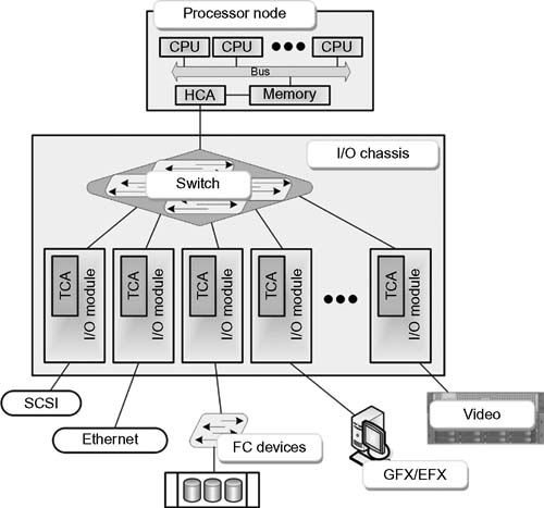
Figure 10.11 Single host InfiniBand Architecture (IBA).
IBA supports a range of applications from being the backplane interconnect of a single host (Fig. 10.11), to a complex system area network (SAN) consisting of multiple independent and clustered hosts and I/O components (Fig. 10.12). The InfiniBand term “SAN” is not related to the term “Storage Area Network,” although to some degree they appear similar, sans the Fibre Channel expectations.

Figure 10.12 Complex multiple host and fabric InfiniBand Architecture (IBA) system area network (from InfiniBand Architecture Specification Volume 1, Release 1.2.1).
System Components
The devices in an IBA system are classified as
•Channel adapters
•Switches
•Routers
•Repeaters
•Links that interconnect switches, routers, repeaters, and channel adapters
The management infrastructure includes
•Subnet managers
•General Service Agents
Channel Adapters and Verbs
Channel adapters are the IBA devices in the processor nodes and I/O units that generate and consume packets. The channel adapter will also terminate a link and/or execute transportlevel functions. It may be either a Host Channel Adapter (HCA), which supports the “verbs interface,” or a Target Channel Adapter (TCA), which is typically used to support I/O devices. TCAs are not required to support the verbs interface.
A “verbs interface” is an abstract description of the functionality of an HCA. An operating system may expose some or all of the verb functionality through its programming interface. A “verbs consumer” is a direct user of the verbs.
Switches
Switches primarily pass along packets based on the destination address in the packet’s local route header. A switch will consume and source packets that are required for managing the switch proper. A switch port may (optionally) incorporate the properties of a physical TCA port.
Routers
Routers will not generate or consume packets, with the exception of management packets. Routers will only pass, that is, forward packets based on the packet’s global route header. The router will replace a packet’s local route header as the packet passes from one subnet to the next.
IBA routers are a fundamental routing component in the architecture of inter-subnet routing, which is provided for by IBA switches. Routers promote the interconnection of subnets by relaying packets between the subnets.
Management
IBA provides for a “subnet manager” and an infrastructure that supports a number of general management services. Each node in the management infrastructure requires a subnet management agent, which then defines a general service interface that allows for the addition of general services agents.
The IBA defines a “common management datagram” (MAD) message structure for communicating between managers and management agents.
Subnet Manager (SM)
The subnet manager is an entity attached to a subnet that is responsible for the configuration and management of switches, routers, and channel adapters. The subnet manager can also be implemented on other devices, such as a channel adapter or a switch.
Subnet Management Agent (SMA)
Each node provides a Subnet Management Agent (SMA) that the subnet manager accesses through an interface called the Subnet Management Interface (SMI), which allows for both local identifier (LID) routed packets and directed route packets.
Directed routing provides the means to communicate ahead of switches and end nodes configuration. Only the SMI allows for directed route packets.
Service Agents
Additional management agents, referred to as General Service Agents (GSA), may be added at each node. The GSA may be accessed through the General Service Interface (GSI), which only supports LID routing. There are several general service classes defined in the IBA, the depth of which is beyond this brief overview of InfiniBand.
Performance and Applications for IBA
InfiniBand can be found in various system architectures, wherever there is a requirement for high-speed, low-latency communications. One area where IB is utilized is in accelerating the parallelprocessing capabilities of multiple GPUs (graphics processing units) for 3D (stereoscopic) and multidimensional rendering of images in real time. In this application, it is imperative that a GPU talk directly to the memory (storage) system so that efficiencies are maximized both during read and write operations, offloading those activities from the CPUs of the rendering farm or workstation(s).
IB is also found in media data centers as the interface between complex storage systems and compression or transcode engine farms. Given the volume of data that must travel from the store as raw content, through the compressor or transcoder, and back to active storage, it is essential to have the highest performance computer (HPC) backbone available to maximize throughput and improve effi ciencies.
IBA provides levels of performance that can be application specifi c to the needs of storage, workfl ow, or processing. The roadmap through 2014 is outlined in Fig. 10.13 which shows how multiple lanes of bandwidth can be scaled to meet the objectives of the enterprise.
InfiniBand performance and road map
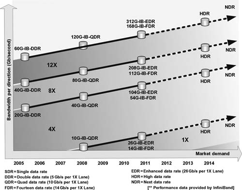
Figure 10.13 InfiniBand performance and roadmap.
Link Performance
Three levels of performance are currently available in the InfiniBand Architecture:
•10 Gbits/second
•20 Gbits/second
•40 Gbits/second
The link speeds provide for low-latency communication within the fabric and enable higher aggregate throughput than other protocols.
Fibre Channel and G igabit Ethernet
The InfiniBand Architecture is complementary to Fibre Channel and Gigabit Ethernet, enabling those networks to connect into the edge of the InfiniBand fabric, which improves access to InfiniBand Architecture-enabled computing resources.
Cabling
In addition to a board form factor connection integral to the IB fabric architecture, InfiniBand also supports active and passive copper (up to 30 meters pending speeds), and fiber-optic cabling (up to 10 km).
IP Storage Considerations
Enterprise-class networks will routinely employ expensive to deploy, often difficult to manage Fibre Channel technology for their high-performance storage networks. Maintenance of such systems are well beyond the capabilities of most small- or medium-sized IT departments, usually requiring outside resources to monitor, diagnose, and tune up when modifications are needed, capacities are reached, or performance requirements change—such as when a new department is created or a major activity is added.
Less expensive and simpler technology can be found by employing IP network (e.g., Ethernet) technology and components for organizations ranging in size from small (SOHO) to large (corporate) users. Organizations can now deploy inexpensive storage networks capable of transporting storage data anywhere Internet access is available or where there is support for SCSI storage commands across that particular IP network.
Whether the storage area network is Fibre Channel based or is of another breed, switches and routers will play an essential role in establishing sufficient IP storage performance through the segmenting of storage traffic from other regular LAN-user traffic, while also maintaining security throughout the entire network architecture.
IP Switches and Routers
Most current IP switches and routers now provide for the highend features necessary to support these activities. Such reliability features should include capabilities for active/active clustered failover, failback, and multipathing.
IP storage implementation performance depends heavily on the selection of the appropriate IP storage switch or router, demanding careful consideration of port speed, segmentation, interoperability, security, and application compatibility.
Determining the Need
When looking at implementing an IP storage network, the first consideration should be to evaluate the need for that IP storage network. It may not be practical to add IP storage if the entity has already deployed an all Fibre Channel storage solution. However, by implementing an inexpensive and well-understood IP storage infrastructure, more servers could be cost-effectively interconnected to the fabric, which could noticeably improve the organization’s server resource availability.
Consider those applications that will be functional on the IP SAN segment, since certain applications may perform better on an IP SAN, with others requiring the performance obtained only on a Fibre Channel SAN. Never be reluctant to do some thorough testing, on your specific network, as an aid in identifying potential compatibility issues with your applications.
Logical Separation Points
Smaller organizations might find themselves deploying only IP storage networks. Larger IT departments already invested in a Fibre Channel storage solution need to determine how or if IP storage fits into their global storage perspective. In concentrated activities, such as found in media content creation or post-production, it might be more practical to place non-media related user data on IP storage, and dedicate mission-critical applications and its data to the Fibre Channel SAN. Here, the breed of IP switching will make all the difference in performance, and may be specifically required in order to attain the expected throughput necessary for those activities.
IP SANs may be more suitable for remote offices where there is a lesser degree of concentrated activities or when there are smaller staffs attached to that local area network. If local, temporary, or scaled-back data exchanges can be managed across the Internet, then it becomes natural to select the IP switches and routers appropriate to those activities.
Other technical considerations should also be included in the selection of IP switches and routers. These include SAN segmentation support and cross domain inter-fabric routing; mapping of zones across SAN segments; or virtualization used to segregate IP SANs—the term VSAN (from Cisco) comes to mind.
Security Considerations
IP SAN security features are a matter of fact given the ubiquitous nature of IP and how it can impair IP SAN security. IP SANs should remain logically separated from other LAN user traffic in order to prevent sensitive data from unexpectedly leaking out across the LAN and onto the Internet. The selection of a switch or router for the IP SAN necessitates an evaluation of the authorization and authentication capabilities of the IP switch or router.
Ports and Connectivity
If iSCSI is implemented as a supplement to an existing Fibre Channel SAN, then the switch and/or router solution will need to implement both IP and FC ports on the same physical device. The availability and performance requirements in terms of the number of ports and their connectivity parameters for iSCSI must provide for adequate expandability. Some iSCSI gateways will combine multiple Gigabit Ethernet ports and multiple FC ports into a single device, allowing for the linking of servers with both iSCSI and FC storage systems.
These devices need multiple protocol and translation support by and between other protocols that are suitable to the specific needs of your application. If required, select an IP switch or router that is enabled to handle translations between many sets of protocols:
•FCP to FCIP
•FCP to iFCP
•FCP to SRP (Secure Remote Protocol)
•FCP to FICON
(FICON is IBM’s proprietary name for the ANSI FC-SB-3 Single-Byte Command Code Sets-3 Mapping Protocol of Fibre Channel.)
Other Features
Advanced features like active/active clustered failover, failback, and multipathing capabilities all help to improve the reliability and availability of the IP SAN.
Active/Active Clustering
Active/Active clustering is a means of having two separate instances running in the cluster, that is, one (or more) per machine. Active/Active clustering refers to a two-node cluster, with each node running server instances, but each with a different set of databases. The setup is conceptually the same as having two Active/Passive nodes, except that one node must be a named instance.
Failback
Failback is the process of returning an operation back to its original configuration following a disaster, a failover, or a scheduled maintenance period.
Multipathing
Multipathing is the establishing of alternate paths to prevent issues when a server is attempting input/output operations and the failure of a given path occurs. The system is corrected by the use of another path associated with a given device.
Management Tools
All IP switches and routers will provide for some level of management, almost exclusively as software, and often as a Web-enabled (browser) user interface. The effectiveness and flexibility of these software tools is extremely important when tasked with the management of any scale of storage system (IP or Fiber Channel).
Tools should allow for the straightforward configuration of these devices and for the routine (and diagnostic) maintenance of the systems. Such management tools should allow for certain performance-monitoring capabilities, such as resource utilization analysis and/or service level (i.e., SLA) management. Intelligent health-monitoring features will aid in identifying faults and should provide for a messaging service capable of alerting an administrator or technician. Faults should all be logged, along with performance parameters so that system trending analysis can be routinely performed either in the background or on command.
Other features such as enhanced monitoring for ISL trunking will aid in configuring or analyzing inter-switch performance and port consolidation.
Acceleration and Compression
WAN centric attributes may be desired especially when IP devices are intended to operate over geographically separate connections. These features are designed to optimize bandwidth and more traffic between sites on an accelerated basis.
Fibre Channel over IP (FCIP) compression will reduce the amount of redundant data, significantly decreasing the total amount of data that are passed across the WAN. FCIP write acceleration and FCIP tape acceleration help to improve storage traffic over the WAN by mitigating the latency caused by command acknowledgements.
Security
The Internet, because of its ubiquity, has become notorious for security problems. Data security for IP and for Fibre Channel SANs must now be combined in order to meet regulatory, data protection, and privacy concerns, making storage security now an even more important topic.
The critical issues associated with SAN implementations, and communications defenses, have generated a storage security gap of growing proportions.
Authentication
Most SAN environments do not address the aspects of authentication; in fact, most SANs are designed using the assumption that authentication will or has taken place elsewhere in the system.
Protocols that have emerged to partially address this lack of security in authentication include
•Fibre Channel Authentication Protocol (FCAP)
•Fibre Channel—Security Protocol (FC-SP)
•DH-CHAP (Diffie-Hielman CHAP)
Organizations frequently presume authentication that occurs at the file or record layers (i.e., databases) should be sufficient. This presumption ignores lower network level authentication requirements and would be analogous to requiring authentication of a Web application, yet not commanding authentication for a Web server SSH connection or for an open telnet session—both of which open the door to full data compromises.
At the simplest level, management applications used to administer storage data will usually require a username and password for authentication. Other applications having access to the SAN may provide for indirect authentication. At other levels, authentication modules have been developed for switch-toswitch, node-to-node, and node-to-switch connectivity.
The security protocols that have been introduced as of the mid-2005 to 2010 time frame are aimed at alleviating security concerns that are becoming extended into FC SANs as a result of the introduction of IP-based connectivity and IP storage platforms. The following sections will explore some of those protocols and implementations.
Fibre Channel—Security Protocol (FC-SP)
FC-SP is a specification for Fibre Channel security that features device-to-device authentication, management of authentication passwords (known as shared secrets), data origin authentication, and anti-replay protection was developed around the 2006 time frame as part of the INCITS T11, Project 1570-D. The provisions of this protocol are designed to safeguard SAN traffic against unauthorized access and to aid in preventing accidental or unintentional configuration changes that would interrupt application availability.
FC-SP was drafted as a modular standard to define different levels of compliance. To claim FC-SP Authentication Compliance (AUTH-A), the storage system, storage networking device, or the host bus adapter (HBA) must support switch-to-switch, device-to-switch, and device-to-device authentication using the Diffie-Hellman Challenge Handshake Authentication Protocol (DH-CHAP) with a NULL DH group.
Before allowing communication, per this profile, FC-SP requires that the devices must authenticate to each other using a unique value, known as a “shared secret.” To perform the authentication, each fabric component must either know the shared secret associated with other entities with which it is communicating or rely on a third party that knows the secret, such as through the use of a Remote Authentication Dial In User Service (RADIUS) server or a Terminal Access Controller Access-Control System Plus (TACACS+) server.
In turn, each device must also know, or be able to access, its own secret. This process eradicates the possibility of unauthenticated communication. The concept is effective in safeguarding the SAN against a rouge server instigating a network attack or a switch that impersonates a valid device.
Device Identity
Many Fibre Channel-specific access control mechanisms rely upon the device identity known as port World Wide Name (pWWN), a sort of MAC address, but one that is not intended to be secure or hack-proof. Many management tools will legitimately allow the changing of the pWWN for a device relatively easily. However, the upshot of potentially unauthorized changing of a pWWN is that those traditional Fibre Channel access controls are now circumnavigated with the intention of maliciously affecting the network, resulting in damaging outcomes for the enterprise.
Fibre Channel access control functionalities that traditionally depend on the pWWN include the following.
Zoning
Zoning is a basic tool in FC used to restrict communications between given groups of devices.
Port Security
Port security is the binding of a specific device to a specific switch interface with the intent of minimizing connection errors.
Logical Unit Number (LUN) Mapping and Masking
LUN mapping and masking is built into storage devices or servers to functionally limit or profile the data access depending on host access authorization.
The flexibility of FC-SP allows devices that support the protocol to operate in a fabric that includes non-FC-SP compliant devices or resources. The protocol authentication guarantees the effectiveness of those Fibre Channel access control approaches traditionally in use, even if a would-be attacker uses the pWWN of a valid device (see Fig. 10.14).
Other security methods for authentication that utilize FC-SP may be directly implemented by the manufacturers of the switches or routers themselves. Management access using the HBAs is another means to control access to FC storage systems. Bidirectional parameters enable the HBA to authenticate in one direction, such as when a server authenticates a switch, and then bidirectionally when each device authenticates the other. By offering the choice, one-way being easier to deploy, but twoway being more secure, the users have choices that can reflect the overall architecture of the network storage system.
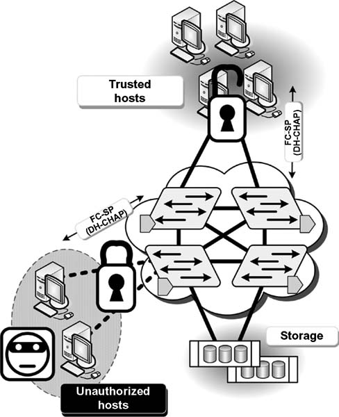
Figure 10.14 By implementing DH-CHAP authentication through the HBA, host threats are prevented.
Authorization
Authorization parameters are usually provided with WWNs derived from the Fibre Channel HBAs. WWNs can be port WWNs (pWWNs), which identify the port, or node WWNs (nWWNs), which identify the node on the fabric.
Encryption
In most SAN environments, encryption does not exist unless a third-party at-rest encryption device is used. Encryption at- rest is when data are physically stored in an encrypted manner. From the standpoint of security, this can be appealing. Consider the case of two databases: database A (which has encryption in- flight) and database B (where there is encryption at rest). If someone decides to compromise database A, and assuming the hacker has database A in their hands, the data could then be read like any other file. In other words, if data can be copied or taken to another environment, then none of the security measures put in place to protect the data are enforceable.
Natively, Fibre Channel does not employ encryption in any of layers 0 through 4.
Auditing
For most SANs, any auditing aspects would be enabled only at the device or application level, such as in a Fibre Channel switch or a management application. While there is error management possible via the fabric, there are typically no provisions in most SANs for security auditing.
Integrity Checking
Currently, there are no native methods for checking the integrity of the Fibre Channel frames.
Quality of Service (QoS)
Availability is a level of performance, which in turn signifies a quality of service (QoS) level. When storage data become unavailable, the networks as well as the applications will quickly disintegrate. The aspect of availability, also referred to as QoS, is indirectly available in layer 2 Fibre Channel frames per the error control fields of the FC frame. Nonetheless, there will be more QoS aspects than data availability, although availability is arguably the most important aspect of SAN security.
Further Readings
IETF IP Storage Working Group
Documents that are archived related to the technologies, and the RFCs discussed in this chapter can be found at:
http://tools.ietf.org/wg/ips/
Fibre Channel, SCSI, and InfiniBand trade associations
http://www.fibrechannel.org/
http://www.scsita.org/
http://www.infinibandta.org/
LISA 2010, San Jose, CA November 2010 Proceedings
“Using TCP/IP Traffic Shaping to Achieve iSCSI Service Predictability”
J. Bjørgeengen, University of Oslo; H. Haugerud, Oslo University College
Network Emulation with NetEm
Stephen Hemminger, Open Source Development Lab, April 2005