1
INFORMATION, DATA, AND VIDEO
The process of digitally storing moving images and sound begins by converting once analog video and audio signals into a stream of discrete representations of binary numbers corresponding to sampled levels of chroma and luminance (for video) or for audio, correlating the changes in dynamic air pressure, which have already been converted into electrical signals as they were captured by transducers over time. In the digital media world, this string of binary information is represented as data and is often referred to as bits and bytes.
The recording function collects, organizes, and retains this data in a format that can be recovered for reproduction as visual information on a display or audible information on a loudspeaker-like transducer. In between the collection and the reproduction phases, the data is retained on a media form. The retention platform is referred to as storage, which can be both a process (i.e., the process of actually capturing or placing the data onto a recordable media) and the physical media itself (e.g., a magnetic hard disk, a lineal videotape, or an optical disc such as a CD-ROM or a Blu-ray Disc).
KEY CHAPTER POINTS
- When does data become information
- Qualifying structured versus unstructured data
- Requirements for the storage of moving images
- Identifying analog composite and component video signal sets
- Digital video recording explained in terms of its components
- Elements of digital video (bit depth, colorimetry, and formats)
Data Structure
In general, data may be classified as either unstructured or structured. The factor for classification is determined by how the data is stored and how it is managed. Rigidly defined data is much easier to access and manage than random sets or elements that are arranged in nondiscriminate structures.
Rigidly structured data is traditionally relegated to databases that are built and maintained by a fully fledged database management system (DBMS). Unstructured data is considered “everything else”; however, there is an area in between, which is neither rigidly structured nor completely unstructured. This gray area is called semistructured because it has a reasonable amount of order or grouping but is clearly not consistent across an enterprise, a department, or even an individual.
In business, more than 80% of an enterprise’s data that is typically used for non-media-related purposes is unstructured. This raises huge concerns for the enterprise as unstructured or semistructured data consumes an enormous amount of storage and is extremely difficult to manage.
Taking an ad hoc approach to data structures for media-related data extends the complexities well beyond what the traditional business space has had to face—with the issues and concerns growing even larger. From this, the business and technologies of storage have become a science.
Information
Data that is created either by individuals or by enterprises needs to be stored so that it can be accessed and easily recovered for processing at a later time. There is no reasonable purpose for data unless it is capable of being presented in a meaningful form. In the business world, the knowledge and intelligence derived from this data are called information.
Before the current digital age, data were collected on printed paper and stored in filing cabinets or placed on library shelves as books or periodicals. Information could be gathered from this format because there was a structure for accessing the data that could be configured in a repeatable and definable classification. The Dewey Decimal Classification (DDC), also known as the Dewey Decimal System, was developed by Melvil Dewey in 1876, and is an example of a proprietary system that is used for library classification. The DDC is one methodology for arranging data in a structured classification.
Today, information is categorized by myriad methods each tailored to a product, an application, a location, or a service. Much of the information presented is dependent on a form of indexing. The indexing uses the concepts of tagging to put the data into a structure that is usable by others. Search engines have become the foremost means of discovering that information.
Given the enormous and growing amounts of media-related information, the value of intelligent storage and the systems associated with searching and retrieval are being elevated to new proportions. Managing the storage systems, and complimentary distribution paths such as networks and transmission devices, is becoming a significant part of what was once an area dedicated to the information technology (IT) sectors only.
For the media and entertainment industries and the public and private business sectors, these concepts are rapidly changing, resulting in a new paradigm for those systems associated with the storage of media-centric data and information.
Storing the Moving Image
Film was and remains one of the most notable forms of storing visual information either as a single static format (as in a photograph) or a series of discrete images on a continuous linear medium (as in a motion picture film).
For at least the past three decades, moving images and sound recordings have been stored on various media including wires, plastics and vinyl materials, rigid metallics, or other polymers, but primarily these recordings have been captured on the most well-known magnetic media, simply referred to as “tape.”
The information contained on this lineal magnetic recording media is often segregated by the type of recorded information contained on the media, that is, sound on audiotape, visual images with sound on videotape, and for the computer industry bits representing binary information on data tape. Over the course of time, the format of these audio-, video- and datarecording processes has moved steadily away from the analog recordings domain toward the digital domain. This migration from analog to digital recording was made possible by a multitude of technological innovations that when combined into varying structures, some standardized and others not, formulate the means by which most of the audio, visual, and data are currently retained (see Fig 1.1).
However, these are all changing, as will be seen and identified in the upcoming portions of this book. Videotape as a recording and playback medium is gradually, but finally, moving away from the traditional formats of the past nearly half century.
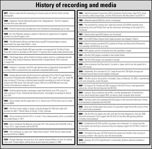
Figure 1.1 A selected history of recording and physical media development.
Digital Video Recording
Digital video recording is a generalization in terminology that has come to mean anything that is not expressly an analog recording. These much belabored references have worked their way into every facet of the industry, compounded even more by the widespread introduction of high definition and the transition from analog over-the-air transmission to digital terrestrial television (DTT) broadcasting.
Clarifying 601 Digital Video
It goes without saying that digital video brought new dimensions to the media and entertainment industry. For the video segment of the industry, this began in earnest with the development of standardized video encoding in the 1980s whereby interchange and formalized products could store, in high quality, the video characterized by its original description as CCIR 601, which later became known as ITU-R BT.601 when the CCIR, International Radio Consultative Committee (French name: Comité consultatif international pour la radio), merged with others, and in 1992 became the ITU-R, International Telecommunication Union- Radiocommunications Sector.
As with many emerging technologies, technical jargon is generated that is filled with marketing hype that makes the concept “sound good” regardless of the appropriateness or accuracy of the terminology. Digital video recording was no different. With its roots embedded in analog (NTSC and PAL) structures, digital video terminology has become easy to misinterpret. In the hope that the readers of this book will be given the opportunity to “get it right,” we will use the terminology that is standards based, or at least as close to the industry accepted syntax as possible. To that end, we’ll start by describing the migration from analog component video through to compressed digital video storage.
Analog Component Video
Prior to digital video-encoding technologies being used for the capture and storage of moving media, videotape transport manufacturers recognized that the image quality of moving video could be better maintained if it was carried in its component video structure as opposed to the single-channel composite video format used throughout studios and transmission systems prior to digital (e.g., as composite NTSC or PAL video). Not unlike the early days of color television signal distribution in the studio, where video would be transported as discrete components throughout portions of the signal chain, the process of video interchange between analog tape recorders was pioneered by the early use of “dubbing” connector interfaces between component analog transports.
Analog Component Signals
In the era of early color television broadcasting, the impact of the legacy monochrome (black and white) signal sets remained as facilities moved from hybrid monochrome and color systems to an all color analog television plant. Those component video signals that comprised the technical elements of video signal systems consisted of both composite signals and discrete sets of signals including the primary red-green-blue (RGB) triplet set of color signals. Depending on the makeup of the video processing chains, additional horizontal and vertical synchronization (H and V) signals, composite sync (S), and color subcarrier (3.58 MHz color burst) might have been distributed throughout the facility.
Often, these signals were carried on individual coaxial cables throughout the television plant. As color television systems developed further, the number of individual discrete signals diminished, except for specialty functions such as chroma keys. The concept of component video signal technologies reemerged in the early 1980s, enabled by the desire to carry other sets of individual channels of component analog video on either pairs or triplets of coaxial cabling.
Two fundamental signal groups make up the so-called component analog video signal set. The signal set described by the three primary colors red-green-blue, better known as simply RGB, may be considered the purest form of the full bandwidth set of video signals. In a three-channel color television imaging system, a set of signals is generated from the light focused in the camera’s lens and is passed to the prismatic optic block (see Fig 1.2). When the field image passes through the prism and is optically divided into three images, each corresponds to one of the elements of the RGB color set. Depending on the electrical makeup of the image, which may be a CCD or a CMOS imager, the electrical signals generated by the imager are amplified and their components are applied to electrical systems in which they are eventually scaled and combined according to the signal standard to form a television video signal.
Analog component video signal sets found in video systems may include more than just the primary RGB triplet of signals. These additional component signal sets, designated as RGBS, RGBHV, or RG&SB signals, are often used when connecting computer-generated video graphic signals to displays configured for video graphics array (VGA) signals and beyond.
In its “pure” format, RGB signals should be considered fullbandwidth representations of optic-to-electrical energy. In this format, full-bandwidth RGB signals are rarely used in video processing or video production. RGB signals generally do not use compression and in turn do not impose real limits on color depth or resolution. As a result, they require a huge
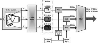
Figure 1.2 Component video to serial digital video bit stream signal flow, filter, and multiplex (MUX).
amount of bandwidth to carry the signal and contain significant amounts of redundant data since each color channel will typically include the same black-and-white image associated with the percentages of color information for the RGB channel they represent. Recording this type of RGB signal onto analog lineal videotape would be impractical, though not necessarily unimplemented. While the digitization of the “pure RGB signals” would offer the cleanest preservation or integrity of the image, it is fraught with a myriad of issues far beyond the topics of this section.
Typically, when component signals are used in analog or digital video recording, the RGB components are not used but instead a different scaling and combination referred to as color difference signals or sometimes just component video signals are used. Component video signals are scaled differently than the straight pure RGB signals, given that video displays must account for both the human visual system and the physical properties of the display system. Because of these issues, we alter the scaling of the RGB signals to produce a nonlinear set of video component signals that are used in displays, digitized videos, and compression systems. When these nonlinear signal sets are derived, they are referenced with prime (′) marks that follow each of the alpha characters. Then, the three primary colors are designated as R′G′B′.
Color Difference Designations
When referring to color difference signal sets, the term luma is established to reference the colorless video channel. Luma should not be confused with luminance, which is confined to color science. Luma is derived from the properly scaled combinations of the red-blue-green channels. Luma is designated by Y′ (pronounced as “why” + “prime”) and is specifically and directly used in the video system terminologies to distinguish it from the color science-related Y (“without prime”) luminance.
This luma (Y′) signal is derived from the scaled set of the original full-bandwidth RGB-triplet color set that is used in video applications, referred to as R′G′B′. The Y′ component is computed as a weighted sum of these nonlinear R′G′B′ primary components using coefficients calculated from the reference primaries according to the method given in SMPTE RP 177 Recommended Practice. The derivation of the Y′ signal commonly used for analog encoding is
Y′ = 0.2126R′ + 0.7152G′ + 0.0722B′
The associated video signal set that contains the color information component is referred to as chroma and is designated by the letter C. You may see differing variants of the Y and C combinations throughout video signal technologies (refer to Table 1.1 for more information).
Digital from Its Components
When applying analog component video to digital video applications, the three nonlinear video signal information sets are transformed into one luma signal and two chroma signals. These signals are subjected to nonlinear processing, with the chroma signals scaled and band limited. For digital video applications, the luma and chroma sets are designated as Y′, C′R, and C′B. This digital signal format is described in ITU-R BT.601, the convention stating that the C′R and C′B pair will represent color difference signals with values from 16 to 240 (in 8-bit quantization).
For applications in which the analog video signal representations are used in color encoding and analog interfaces, the three nonlinear video signal information sets are transformed into a different set of three color difference signals, containing one luma and two chroma channels. As with the digital set, each of these signals has been subjected to nonlinear processing, with the chroma signals band limited. They are designated as Y′, P′R, and P′B. By convention, P′R and P′B represent color difference signals in the analog video signal domain whereby the typical voltage excursion is between -350 mV and +350 mV. The luma (Y′)
Table 1.1 Component Analog and Digital Recording Levels

signal has a voltage excursion (i.e., a dynamic range) of 700 mV. Figure 1.3 shows how the color difference matrix generates the Y′, R - Y′ and B - Y′ signals from the original RGB signals.
Auxiliary Signals
An auxiliary component, sometimes called the alpha channel, is designated by the letter A. This component may optionally accompany R′G′B′ and Y′C′B C′R signal sets. The interfaces denoted as R′G′B′A and Y′C′BC′R A include this auxiliary component that, when present, has the same signal characteristics as the Y′ or G′ channel, that is, a colorless signal prescribing the luminance level of the video signal.
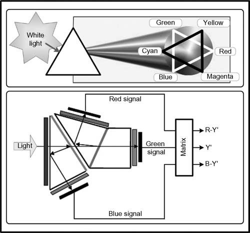
Figure 1.3 Component video signals derived from captured light, separated by a prism, and presented to a matrix to produce the color difference signals used in analog component and digital component video signals.
YUV Confusion
Another derivation of component analog video is used by those areas using the 625-line 25-frame-per-second PAL (Phase Alternating Line) standard, as opposed to the 525-line 30-frameper- second NTSC (National Television Systems Committee) standard. This signal set, called YUV, has a similar structure with the luma channel (Y) derived from scaled nonlinear red-green-blue (R′G′B′) signals:
Y = 0.299R′ + 0.587G′ + 0.114B′
The PAL system refers to its color difference signals as U and V, which like NTSC, are used to carry the chroma information. For composite signal encoding, each has a typical bandwidth of 1.3 MHz:
U = 0.493(B′ - Y)
V = 0.877(R′ - Y)
Note that some documents may show that the U signal equals 0.492(B′ - Y).
Although the terminology is widespread, when the application involves conversion to component digital video, these Y′UV color difference components are almost never used. The improper association of YCBCR with YUV has remained for some time, the latter being a different color space that is not used in digital media, and that should only be applied in composite analog PAL-based signals (i.e., in non-NTSC analog TV transmission or videotapes).
Bit Depth
To fully describe digital video signal systems, especially when addressing digitally encoded formats, additional information is necessary. Digital video specifications must state whether the digital representation employs uniform quantization (linear), PCM, 8-bit, 10-bit, or 12-bit video encoding. The importance of this becomes much more obvious when considering the formats and structures of the capture (ingest) processes, the transport, and the storage of the digital video. The bit depth can play a significant role in the metrics related to file sizes and thus storage capacity, plus the ability to retain a greater signal quality when used in video production, special effects, cross or film conversion, and archive.
Additional considerations having to do with digital image processing are also impacted as the numerical calculation requirements are increased as well.
Colorimetry and Conversion
Another important metric related to colorimetric analysis and opto-electronic transfer functions of the signal is the defining of the proper color space parameters. These parameters are of particular importance whenever signals are transcoded or repurposed from one format to another, e.g., when converting from a standard definition to high-definition format. The standard that defines these parameters is ITU-R BT.709.
Legacy material created on systems before the acceptance of SMPTE and ITU-R standards may contain different or improper colorimetry parameters. Although the differences are small and most likely noticed only with precision test materials, designers and users should be aware that some of this legacy material in this format was originally created using the SMPTE 240M standard, which prescribed a different colorimetry relationship.
When converting between digital and analog representations of signals, for both displays and production equipment, it is important to recognize that the colorimetry can be affected. Most of the available professional video signal processing hardware provides the proper scaling and conversion software, but systems employed in the early 1990s and even some flavors of softwareonly codecs may not properly apply all of the conversion parameters. Only modern test signal and measurement systems can detect these colorimetry discrepancies.
Typical groupings of component video may be comprised of two signals (Y and C) as is used in S-Video or a triplet of luminance and color difference signals (YPBPR), commonly found in analog videotape formats or the signal outputs of consumer devices such as gaming consoles or DVD players.
A Digital Media World: Going Forward
The developments in digital media recording took several steps and paths to get to where it is today. The formats that are commonplace today evolved through a combination of various moving media technologies, extraordinary improvements in computing capabilities, and adjustments to production and information technology workflow, as well as a gradual industry acceptance.
There are dozens of excellent books and thousands of citations online that describe the overwhelming number of digital media formats and their terminologies. It is sometimes complicated and often difficult to understand completely just how these various flavors of media interoperate, due in part to some of the confusion raised by the vernacular that came out of the industry needing to identify the previously undiscovered forms of content and program production. In many situations, marketing buzzwords were created to describe the functionality of the services and the systems. Many of today’s file formats for digital recording came directly from the manufacturers, who created their own means and methods for the digital capturing and retention of these moving images.
These myriad variations in compression formats, bit rates, coding structures, wrappers, containers, and nomenclatures are aimed at encouraging the acceptance and the widespread use of digital video and file-based workflows that abound throughout the public and private sectors of the industry.
We have seen the evolutionary paths of videotape recording from analog to digital. Videotape is still with us, albeit not nearly as prominent as it was at the conclusion of the previous millennium. The legacy content in vaults, on shelves, and in the basements of homes and businesses all tell a story that needs to be preserved for future generations. The means and methods of that preservation hinge on how that material is stored and how it can be recovered much later in history.
Going forward, it is evident that the storage medium of choice will eventually drive videotape recording away from its current linear magnetic media format. The future, at least for the present, appears to be centered on solid state, magnetic- or optical-based disk storage, with a continued dependence on linear magnetic digital tape recordings for archive and preservation. The next major task then must clearly focus on managing that media for the long term.
Further Readings
Society of Motion Picture and Television Engineers Standards. http://www.smpte.org/home/
International Telecommunication Union — Radiocommunications Sector (ITU-R) standards. http://www.itu.int/
Advanced Media Workflow Association. http://www.aafassociation.org/
Watkinson, J. (2008). The art of digital video (4th ed.).