3
VIDEO MEDIA SERVERS
In August 1994, station KOLD-TV (Tucson, Arizona) installed an HP (Hewlett-Packard) Broadcast Videoserver as a key part of its strategic upgrade to the station’s broadcast technology and a replacement for its current robotics-based videotape commercial delivery platform. It was the first commercial broadcast installation of a videoserver platform although cable was using similar technologies for movie delivery and ad insertion in a similar time perspective.
The HP videoserver product, and others that would be announced in the next several months, would begin an era that would change the course of broadcast television forever.
This chapter outlines the videoserver for those unfamiliar with its physical systems, signal sets, control protocols, and basic storage systems.
KEY CHAPTER POINTS
•Distinguishing video and media server platforms from disk recorders, and their processors, the tape-based robotics controlled library management systems
•A historical overview of early videoserver systems for broadcast transmission and video media production
•Descriptions of videoserver components, their input and output interfaces, standard- and high-definition transport formats for videoservers, AES-embedded and Dolby-compressed digital audio, and serial data transport interface (SDTI) as SMPTE 305M-2005
•Descriptions of machine control protocols, such as VDCP and others, along with time code and ancillary data sets commonly found on videoservers
Carrying Over from the DDR
The logical extension of the digital disk recorder, for professional applications, was to provide more computer-like serving capabilities. This required an increase in performance (bandwidth or throughput). It further required the capabilities inherent in computer server platforms such as shared and protected high-performance storage, hot-swappable easily maintained drive systems, expansion capabilities for storage growth, and a host of other features (which will be discussed later in this chapter) be made available such that the services provided by these new devices, called video or file servers, would be reliable enough for broadcast users to purchase them and really put them into service.
Sony Betacart
The broadcast marketplace had been using cassette-based robotic “cart machines,” from the Sony Betacart BVC-10 (see Fig.3.1) through the Sony LMS (a later digital version called the “Library Management Systems”) and others included Lake Systems “LaCart,” Odetics, and Panasonic flavors since the 1985 time frame. The author of this book was fortunate enough to place one of the first Sony Betacarts into service on June 22, 1985, at the new Seattle television station—KTZZ-TV 22. At that time, a complete Betacart package consisted of the following:
Sony Audio matrix switcher—BVS-A10
Sony Video matrix switcher—BVS-V10
Sony Remote control box—BVR-20
Sony Betacam playback decks—4 ea. BVW-11 (oxide-based transports)
Sony remote control keyboard (programmers keyboard)— BVR-11
Sony barcode label printer—BVBP-11
Sony barcode writer (programming keyboard for printer)—BVBC-10
Sony operating system software disks—BZC-xx (uses 720K “3.5 disks) VDU—a 12” monochrome video monitor (used as the display CRT for programmers)
Figure 3.1 Sony Betacart model BVC-10 from 1986. Reprinted from SMPTE journal, 95(10), October 1986, 1066.

The weight without decks was about 1000 pounds, and the power was 13 A at 120VAC single phase. The system was used to play both commercials and fulllength programs.
Over time, many similar competitive roboticsbased videocart machine products were introduced to the marketplace (see Fig. 3.2 for a depiction of the Sony Betacart workflow). These incredibly expensive devices remained in sustained operations throughout the development of the videoservers that ultimately pushed them into retirement.
The first implementation of videoservers for those facilities with videotape-based cart machines was to provide a disk-based cache between the tape library and the final air chain. Tapes would be loaded from the tape library to the videoserver cache and then played to air. Intelligent software would request tapes not already on the server to be loaded, where the automation system would then transfer the tapes into the server based on the SOM (start of message) and EOM (end of message) metadata held in the tape library’s database.
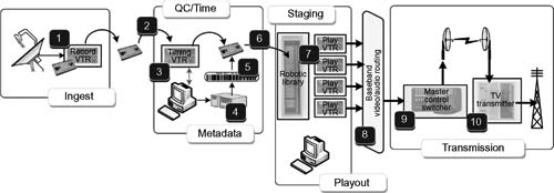
Workflow for Ingest — Preparation — Scheduling — Playback — Transmission
[1] Videotape loaded into VTR for program record
[2] Videotape shelved, reloaded to timing VTR[3], manually cued, start of message (SOM), end of message (EOM), metadata logged and label printed [4], label applied to tape cassette, tape then shelved until needed for air
[6] Tape is retrieved, loaded into robot [7], at scheduled time robot loads cassette to play VTR automatically, upon trigger from master control, content plays out to routing switcher [8].
[9] Master control switches program into playout stream, signal links to television transmitter [10] and program plays to air
Figure 3.2 Workflow of early automated videotape-based robotic library play to air.
Since the robot controllers and the tape transports were the “weakest links” in the systems, the disk-based cache system provided a level of protection and redundancy that stations heretofore had to create secondary dub reels (as backups) to achieve in order to protect the on-air integrity. Worse yet, in very highprofile markets, the stations used two Betacarts (or other robotic libraries) in main and protect modes—an enormous cost that was supplanted by the introduction of the videoserver cache.
Universal Server Approach
Influenced by the emergence of multimedia, including early ventures into interactive television, manufacturers of computer and data-centric systems endeavored to find a means to exchange video and audio media between clients on their network. Companies sought to develop and offer a complete information management solution for users who looked to capitalize on the economic advantages of accessing any form of data, for example, relational, spatial, text, images, audio, and video over any network or from any location.
Oracle was an early player in this particular domain-linking video with business applications. In 1995, as an extension to their existing Oracle7 relational database management system (RDBMS) applications, the company developed the Oracle Videoserver. The product extended the company’s lead as the “first and only provider of a ‘universal server, ’” video-enabled existing applications, and allowed for the creation of a new class of enterprise multimedia applications such as training on demand, multimedia kiosks, and online video help.
These “videoservers” were not aimed at the professional or broadcast video marketplace as they lacked the deterministic and visual quality properties necessary for real-time record and playback of audio and video in an isochronous fashion. Nonetheless, they did provide the catalyst for what would in less than a decade become a paradigm shift in how audio or video media would be distributed.
Videoserver Differentials
The professional or broadcast videoserver, in contrast to a DDR or the “data-centric” Oracle model described previously, takes the features of the single-channel digital disk recorder (DDR) and multiplies them across one-to-many inputs and/or outputs. Depending on the architecture that the server manufacturer employs, a server channel will usually be at least a single input (for recording) and single output (for playback). The ratio of the number of inputs and outputs varies but in most cases is at least a pair or multiples of inputs and/or outputs.
Videoservers nearly always share media data from a common storage platform. Functionally, a videoserver performs more than one operation, that is, it needs the ability to record (ingest) and play out (playback) simultaneously.
Tektronix PDR100
The Tektronix PDR100, produced in February 1995, was one of the early videoservers that took the concepts of a DDR and coupled them into a four-channel video recording and four-channel video playback system sharing a common storage system integral to the product.

Figure 3.3 Basic functional diagram of 2-input by 2-output real-time videoserver. (1) Conversion and encoding to files; (2) decoding and conversion from files for playout; (3) server system with file system, file management, and storage; (4) real-time operating system (R/TOS); (5) user interface, record, playout, metadata and database, control interfaces between user or automation and videoserver.
The Profile series videoservers were designed to emulate the quality of the Sony Betacam SP (metal oxide) videotape format. The compression format was motion-JPEG, with its storage platform either internal to the chassis or with an optional disk expansion unit. The integral storage system was capable of incorporating 4, 8, or 12 4-Gbytes SCSI hard drives (considered “large” for that time period).
The optional PDX103 disk expansion unit had its own power supply and as many as 16 additional hard disks in a unit that was four-rack high, 25.5 in. deep, and 19 in. wide. The expansion unit came with either eight drives (two banks of four drives supporting two disk recorder boards in the PDR100), a single bank of eight drives to support one disk recorder board, or 16 drives that would fully utilize the capacity of two disk recorder boards.
Tektronix saw the potential of the videoserver early. They quickly offered peripheral products, such as the PLS-200 Exabytebased tape library for archive, and a series of drive expansion chassis that allowed the user to scale the system to their own requirements.
Within two years, Tektronix introduced the Profile PDR200, also a two- or four-channel unit using 9-Gbytes Ultra-SCSI disk drives. The updates included 24-bit AES/EBU digital or analog audio, a 30 Mbits/second internal bandwidth, and a Fibre Channel networking interface. For its 20% increase in price over the PDR100, you doubled the storage, added digital audio, and increased the bandwidth.
Other manufacturers and products, including ASC Audio Video Corporation (which was acquired by Leitch in September 1997), Hewlett-Packard’s MediaStream Server Broadcast Series (later Pinnacle Systems and eventually Avid Technology), and SeaChange Technology (later SeaChange International), began their entry into this emerging marketplace in the same time frame or very shortly thereafter. By 1998, there were at least five significant players building some form of videoserver for broadcast use. The start of the era of tapeless operations was emerging.
Applications of the Early Server
Other professional videoserver products began appearing in the marketplace once the acceptance, and the operational understandings, were firmly in place. Broadcast videoservers were used initially in two basic operating modes. For those broadcasters using aging cassette-based or videotape-based commercial and interstitial playback systems, for example, an Odetics, Panasonic MARC, or Sony Betacart/LMS, the videoserver would become the on-air playback device and the cassette system would become the backup. This workflow found tapes being made for the cart machine and those same tapes being dubbed into the videoserver, a process not unlike the backup protection reel that was common in the early days of the cart machine for major markets or for those with apprehensions about having only a single commercial playback device.
Cart machine manufacturers would begin incorporating the videoserver platform into the cart machine system, using it as a cache for playout instead of relying on multiple discrete individual tapes that were prone to failure (see Fig. 3.4). Tapes would be kept in the cart library and then dubbed via an automation controller into the server for playout. Last-minute changes that were not previously dubbed into the server could be played back from the cart machine.

Combination videoserver cache and robotic library
[1] Videotape loaded into robotic library.
[2] Under integrated control with robotic library and videoserver, clips or entire breaks are cached to the videoserver [3].
Upon playout from the videoserver [3], the same cassettes would playout from the robotic library, providing parallel paths for redundancy. Should the server fail to play, or if a last minute change was made for material not cached to the videoserver, the alternative playout path [4] would be used.
Figure 3.4 Videoserver implementation model with robotic library and videoserver acting as a cache—providing redundancy with parallel operating modes and ability for lastminute changes.

Primary and protection (mirrored) videoserver model
[1] Videotapes, or other sources, are dual ingested [2] to two videoservers, with the same mirrored databases, and identical files (content) on both.
[3] Main or primary air playout comes from this server. The identical files are loaded and played out from the protect videoserver [4], in synchronization with each other.
Figure 3.5 Mirrored videoserver implementation model in which two identical servers contain the same material (content), and each play back in synchronization with each other, in a “primary” and an alternative “protect” mode.
In many systems, especially where the videoserver was the only ingest and playout device, users would install two systems that ran in mirrored AIR and PROTECT configurations (see Fig. 3.5).
Servers for Movies and Digital Ad Insertion
Preparing to capitalize on the cable industry’s aggressive deployments, another form of server would be necessary, which could deliver audio or video content without the stringent requirements of the baseband videoserver. Television ad sales operations were looking for an option other than the (conventional) videoserver. Cable operators (MSOs) looked toward that “singlechannel integrity” platform from which to deploy their digital ad insertion systems.
In November 1995, SeaChange—already a major player in the cable industry—introduced its second-generation Videoserver 100 platform, bringing to the world a new avenue in (digital) ad insertion. The platform supported a variety of wide-area networks such as T1, Ethernet, FDDI, ATM, and SONET. It enabled the cable operators to quickly transmit ads and infomercials from their business office to multiple headends.
In this same time frame, the delivery of long-form videos of any length would become yet another requirement for digital videoservers. These systems would support a wide range of video on demand applications including near video on demand (NVOD) and time delay, provide for extensive storage capability, and utilize high-quality MPEG-2 compressed digital video for delivery.
Added Functionality in the NLE
Nonlinear editing systems (NLEs), in their early days (ca. late 1980s), combined the functionality of a DDR, the operational interfaces of an edit decision list (EDL), and a relatively new introduction called a timeline editor. The NLE, dominated by Avid Technologies, Inc., which was founded in 1987 by William J. Warner and introduced its first product the Media Composer in 1989, would become the benchmark and de facto standard until the era of direct desktop editing. The NLE in general was at first a proprietary purpose- built system that captured individual program segments, manipulated and processed the video and audio, and then output a completed program. The user interface was a computer display, mouse, and keyboard. The feature sets found in a professional broadcast videoserver were unnecessary for these dedicated, single-purpose units that were used primarily for offline “work prints” and edit decision list generation. In this kind of workflow, a time code print would be approved, and then, the full bandwidth video would be conformed in a linear online edit bay. This would work for quite some time until the image quality was equaled to that of the original material, and then, collaborative and file-based workflows were introduced.
After years of development, NLE devices have become as complex and sophisticated as the videoserver. Entire platforms consist now of mixed ingest, compression, editing, storage, and playout for many sets of user applications including on-set production, dailies, postproduction, effects, and television news. NLEs are sold as software-only versions, which can run on PCs, Macs, laptops, and full-fledged workstations. As dedicated complete systems, these advanced NLE systems are now using complex sophisticated networking solutions at gigabit speeds.
Videoservers as Media Servers
The industry has managed to name these video-based serving platforms with a number of varying and appropriate, in most cases, names. Typically, we see the words “videoserver” intermixed with “file servers” and “media servers.” There is probably no one correct answer. Essentially, a video serving platform is a system of hardware and software that can capture, store, and deliver files that contain moving images and sound. It is further enabled through the use of storage networking (SAN or NAS) for shared storage and heightened bandwidth, so as to deliver multiple streams of real-time, uninterrupted video.
Videoserver Operations
Placing a videoserver into service involves more than connecting video and audio inputs and outputs to the rear panel and turning it on. To effectively utilize the server, a thorough understanding of the underlying architecture is necessary. We’ll begin by discussing the ground-level basics of the videoserver as it applies in the environments used by broadcasters and multichannel video program distributors (MVPDs).
Each manufacturer has its own particular way of configuring its videoserver’s functionality. Some will offer a basic one- or twochannel device that is intended for the simpler functions such as record, library, cache, and playback. These simple servers have limited expansion and are marked for a price niche rather than from an expansion or enterprise-wide performance perspective. This is not to say that this level of videoserver is any less capable of producing images from disks; it was most like designed for limited operations and without a heavy initial price point.
Basic Configurations
Space does not allow us to delve into specific manufacturer configurations for videoservers for many reasons. To do so would mean we’d leave several servers off the list, which wouldn’t be justified. The permutations of server product lines have grown by orders of magnitude since their early introductions in the 1990s, and this would become an oversized book that would read like a catalog, which would become obsolete in less than a year or two. However, we will look into some of the concepts developed by manufacturers simply because they have taken either a unique or a more common approach to building their storage subsystems.
Videoservers at the high end run the gamut from full-bandwidth disk recorders for high-definition video that is used mainly in high-end production environments and digital cinema production and are capable of capturing and storing uncompressed video at high resolutions of SMPTE 292 up through 2K and 4K images; to the lower end, standard definition or streaming media servers for mobile distribution where compression is high, image resolution is moderate, and performance degradation is minimal. In the middle range, there are off-line editors, seldom with less than D-1 quality with MPEG-2 long GOP encoding, which are used strictly for rough cutting with no intention of airing the resultant product.
Impractical Storage
To provide even the most basic understanding about how much drive storage is nominally required, a full-bandwidth standard- definition video disk recorder is going to cut into storage capacity at around the rate of 22.5 Mbits/second for just the uncompressed 8-bit video data only. If you recorded everything, including 10-bit video, embedded audio, and ancillary data, the server would consume 33.75 Mbits/second at even standard-definition (SMPTE 259) video resolution.
An ancient 4-Gbytes computer disk drive is capable of recording about 120 seconds of video at the full 10 bits of ITU-R BT.601, 4:2:2 component digital sampling, and eight channels of AES audio. For broadcast operations, this hasn’t been practical for over 15 years, and now with high-definition content such as SMPTE 292 video, it would be grossly impractical to use discrete, conventional hard disk storage space for any level of daily commercial operations. Furthermore, it becomes pointless to stack multiple hundreds of disk drives, even with the new terabyte drives, into several array chassis and put only a few minutes or seconds of video on each drive, unless you are doing 4K resolution, film transferred imagery for digital cinema mastering.
For these reasons and more, compressed video technology has become the standard for videoserver applications, providing additional storage space with no sacrifices in visual image quality.
Main Videoserver Components
Videoserver systems are fundamentally comprised of two main components. The first is a record/play unit that interfaces to and from the second component, the storage array. In a modular videoserver system, these components are provided with some levels of expansion. Figure 3.6 shows a detailed block diagram of a typical videoserver system.
The record/play unit, essentially a combination of a video coding engine and serving components, consists of several elements, which are described below.
Selectable Baseband Video Inputs
For standard definition in digital or analog formats, either a SMPTE 259M serial digital interface (SDI) or analog flavors in composite and component are presented to the input codec. For a high-definition format, generally both SMPTE 259M and SMPTE 292 baseband SD and HD inputs are presented to the same input port. Professional videoservers, especially those with HD capabilities for broadcast applications, have essentially moved away from any analog composite or component I/O (or would offer them only as options). The inputs may encode the input to either 8 bits or 10 bits, allowing the user to select the depth during server setup/maintenance modes.

Figure 3.6 Videoserver internal signal flow diagrams, components typical to conventional video serving systems with AES audio in four forms: analog, AES unbalanced (75 ohm on coax), AES balanced (110 ohm twisted pair media), and embedded into the serial digital bit stream (SD, HD, or 3 Gbytes/second).
Selectable Audio Inputs
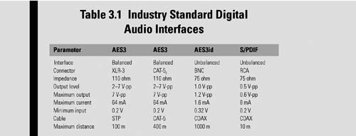
In similar arrangement to the video inputs, audio may either be analog or AES3 standard digital audio. Physical connector (and electrical) options include the 75 ohm BNC (unbalanced) input as AES3id, or as 110 ohm AES3 (balanced) using twisted pair cabling presented to 3-pin XLR connectors. Most servers accept only 48 kHz sampling (20-bit resolution) in at least two sets of AES inputs, yielding four tracks of audio as two stereo pairs. With surround sound and multilingual requirements, many videoservers are providing at least four AES streams providing eight tracks of audio on two groups of AES.
AES-3id-2001
The unbalanced version of the AES implementation is usually carried on coaxial cable with a line driver source impedance of 75 ohms and a return loss of better than 15 dB over the frequency band of 0.1–6 MHz. This form of carriage, usually found in broadcast facilities with discrete (AES) audio, became prevalent in the mid-1990s as AES on digital video transports—and eventually videoservers—came into being.
Sampling
Most of the professional servers will deal mainly with 48 kHz AES sampling (with at least 20-bit resolution) in at least two sets of AES inputs, yielding four channels of audio, generally identified as two stereo pairs. The advent of surround sound and multilingual audio has forced the requirements for at least four sets of AES inputs (eight channels of audio) to fulfill six-channel surround and at least one additional stereo pair of audio for second languages.
Sony/Philips Digital Interconnect Format
The more familiar name for the Sony/Philips Digital Interconnect Format is S/PDIF, which is sometimes simply called the “Sony Philips Digital Interface.” S/PDIF is a digital audio interface method designed primarily by Sony and Philips and later standardized as IEC 60958 Type II (prior to 1998, it was known as IEC 958). S/PDIF is seldom found in the broadcast or professional videoserver domain. There is more likelihood of finding such implementations in an audio server although that would be confined mainly to digital audio workstation (DAW) systems.
An electrical comparison of the variations in AES3 and S/PDIF is summarized in Table 3.1 and in Fig. 3.7.
Conversion between AES3id and S/PDIF
Translating the signal levels between the variances in AES and S/PDIF requires that passive circuitry be added between one format and another. These additional components are sometimes embedded in the front and back end I/O circuitry or may be packaged in discrete interface devices—often called “baluns”—which are frequently found in broadcast infrastructures (see Fig. 3.8).
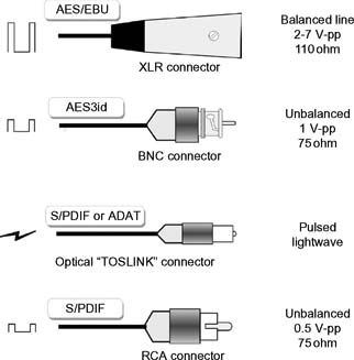
Figure 3.7 Digital audio interface connectors, signal levels, impedance, and signal waveforms.
Embedded Audio
Embedded AES audio, which used to be an option, is now very common on SMPTE 259M or SMPTE 292 inputs and outputs, that is, when devices provide serial digital interfaces (HD/SD-SDI). Embedded I/O saves significantly on connector count and internal conversion. Typically, videoserver products may place as many as 16 or more tracks of audio, which can now be carried on the embedded SDI transport per industry standard grouping specifications.
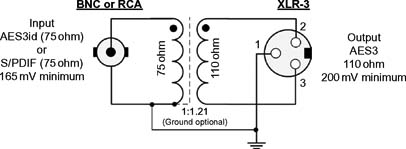
Figure 3.8 Unbalanced 75 ohm AES3id balanced to balanced (balun) 110 ohm AES3 adaptor using passive transformer coupling.
Most of the videoservers generally have the capability to use embedded audio on the output SDI signal even if it had been presented as discrete inputs. Devices with the physical real estate on the chassis may provide both discrete AES and embedded signals on their I/O ports, providing flexibility and negating the need for external embedding or disembedding components.
They may also offer shuffling of the audio tracks on playout. These are manufacturer’s feature choices, and if uncertain the user is cautioned to investigate the specifications prior to implementation.
Dolby Compressed Audio
High definition video drove the requirements for 5.1 channel sound, which is employed in most broadcast television programming. The individual surround sound channels are usually carried as a grouping of PCM AES audio streams, combined and compressed using Dolby E, and presented to the videoserver as a single AES stream. Dolby E allows for as many as eight discrete audio tracks to be encoded and carried on this transport. The signal may be embedded into the SD/HD-SDI transport. At least 20 bits of AES audio must be available in order to carry Dolby E (noting that 16-bit audio reduces that track count from eight to six, still sufficient for surround, but is not generally used).
Dolby Digital (AC3) is the standard for ATSC broadcast emission. However, carrying highly compressed multichannel audio on the video signal presents complications to the videoserver (and some video signal distribution components). First, AC3 is a data set that spans the digital space of both the audio tracks on a single AES stream. Second, the AC3 signal is not frame bound, that is, its data footprint covers more than the area of a single field of video and cannot be properly (cleanly) switched at the video frame boundary points. Third, as a data signal, some servers will not recognize that this is something other than an AES signal and not properly separate it from the video stream or incorrectly slice it for storage on the disk systems. Finally, as videoservers have improved in technical architectures, and the transmission side of broadcast seldom stores AC3 on other than a transport stream server, it has become unnecessary to go through the complicated efforts of insuring that the AC3 signal is properly treated as it is routed (distributed) throughout the facility, except just before emission.
For comparison, Dolby E was designed quite differently from AC3 and presents none of the problems that AC3 does for servers. Nonetheless, the user is wise to validate his or her uses and the specifications of the videoserver audio and video technologies before implementation.
Audio/Video Delay
Components that process the video stream but don’t delay the audio stream to match the video processing delay will result in video frames that will no longer be synchronously aligned to the Dolby E frames. Further processing actions could cause the corruption of Dolby E frames and consequently create artifacts such as audio pops and clicks, once decoded.
Data Processing in Audio Equipment
Dolby E is designed to pass through existing audio equipment. However, care must be taken as Dolby E can no longer be classed as purely audio due to its compressed nature. Equipment used in a system must also be Dolby E aware. This means the equipment may not apply the same audio functions that are familiar with normal audio processing such as gain, phase inversion, audio sample rate conversion, and transitioning or mixing. If this kind of processing is applied to Dolby E data, the stream will be corrupted and may become unrecoverable Dolby E data yielding no ability to decode the Dolby E stream downstream.
MADI
MADI, more formally known as Serial Multichannel Audio Digital Interface, is a standard describing the data organization for a multichannel audio digital interface. MADI is a standard described in AES10-2008 where details include a bit-level description, features in common with the AES3 two-channel format, and the data rates required for its utilization. The specification provides for the serial digital transmission of 32, 56, or 64 channels of linearly represented digital audio data at a common sampling frequency within the range 32–96 kHz, having a resolution of up to 24 bits per channel. MADI makes possible the transmission and reception of the complete 28-bit channel word (excluding the preamble) as specified in AES3, providing for the validity, user, channel status, and parity information allowable under that standard. The transmission format is of the asynchronous simplex type and is specified for a single 75-ohm coaxial cable pointto- point interconnection or the use of fiber-optic cables. The AES10-2008 revision includes minor changes to conform to those revisions of AES3 and AES5-2008, the AES recommended practice for professional digital audio describing preferred sampling frequencies for those applications using pulse-code modulation (PCM), providing clarification of sync reference signals and link transmission-rate tolerance and references for the nonreturn-tozero- inverted (NRZI) and the 4B5B coding schemes.
Serial Data Transfer Interface
Serial data transfer interface (SDT), standardized as SMPTE 305M and extended as SDTI-CP (content package), is a means to interface packetized compressed digital bit streams between devices. This optional interface method has been used on DVCPro videotape transports, some codecs for satellite or other transport platforms, and may be found on some server products such as the EVS XT[2] video replay platforms (http://www.evs.tv).
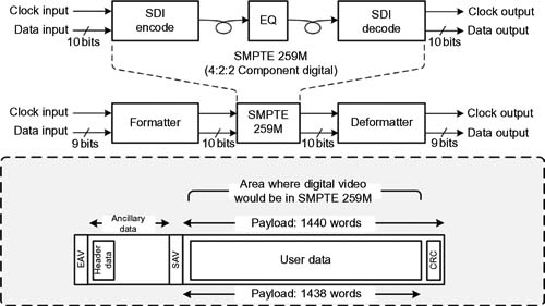
Figure 3.9 SMPTE 305M Serial Data Transport Interface (SDTI).
The SMPTE 305M interface is only defined for the SDI signal transport per SMPTE 259M. A high-definition version, HD-SDTI, is described in SMPTE 348M (see Fig. 3.9 for SD-SDTI and Fig. 3.10 for HD-SDTI).
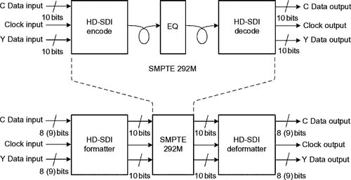
Figure 3.10 Arrangements of HD-SDTI wrapped around SMPTE 292M.
Baseband Video Outputs
Most videoserver platforms will provide a matched set of inputs and outputs, generally in the same formats as the inputs. The exceptions are rare, but it is possible to find products that only accept embedded audio or may only output embedded audio.
Reference Signals
In the majority of implementations, video black burst from the facility’s house reference generator is applied to a dedicated input port on the videoserver. Users may select among this external reference, an internal reference (referred to as “free-run” mode), or one of the digital video inputs or analog (if provided) in a mode referred to as “self-run” mode.
When a videoserver is integrated exclusively into a digital environment, an external reference signal is used essentially only for video signal timing purposes, which allows for the alignment of the playback outputs to the other video signals in the broadcast plant. This reference may be unnecessary if the videoserver functions purely as a file-generation device and has no real-time video output for signal distribution.
Control
Videoservers may be controlled under a variety of interfaces ranging from simple start, stop, and cue from a general-purpose input/output (GPIO) trigger, to a serial control on a balanced differential (RS422) or unbalanced (RS485 or RS232) interface, to a network IP control over an Ethernet carrier.
VDCP
Most videoservers provide at least one RS422 machine control port per channel of the videoserver. The terminology “channel” has no standard definition and may vary depending on the manufacturer’s implementation. Using the common RS422 (or occasionally the RS485 method) of the machine control, emulation of common VTR modes is provided usually as VDCP (video disk control protocol) and is known by a variety of names including the Sony 9-pin protocol, and for extended modes, the BVW-75 extended protocol.
Time code data may be carried between devices over this interface, as well as clip identification or simple asset management information (house number, clip number, etc.)
An example communications protocol (as used by Probel) is:
RS485/RS422, 8-Bit DATA, 1 STOP Bit, EVEN Parity, and 38.4K Baud.
Network IP Control
Some videoserver platforms offer a native control interface over an Ethernet port that communicates directly with either an automation system or other control mechanism.
A goal for a universal control protocol, despite significant advances in the areas of networking, has never been achieved. Attempts to divine such a control code would require a normalization of all the various control interface parameters (e.g., Sony, Ampex, CMX, Odetics) between devices, to one common set of protocols. Unfortunately, such a protocol would presume that all specialized functions, some specific to the videoserver and some to the controlling system, would require a formal standardization process and might result in a reduction of manufacturer-specific performance and capabilities for disk-based systems.
General-Purpose Input/Output (GPIO)
Most of the devices provide at least one external “closure-type” trigger for each channel. GPIO functions may be dedicated to functions such as start, stop, cue, recue, and advance or may be set into software that is assigned during initial setup configurations by the user.
Further descriptions of the control interface protocols are included at the conclusion of this chapter.
Time Code
Videoservers used in broadcast facilities generally find it is necessary to employ some method to catalog or frame count the media being ingested or played back. Digital time and control code, as referenced by the ubiquitous SMPTE 12M standard and for use in systems at 30, 30/1.001, 25, and 24 frames per second, are the commonly accepted means for establishing a time coincident marking of the video frames and runtime in a videoserver. For most of the broadcast facilities, time code will be referenced to a master house clock slaved to the master sync and reference system.
Time code data, specific to the video clip recording, is most often carried to the videoserver from the source VTR over the RS422 serial control interface. Many servers will provide a single linear time code port that applies time code to the server for recording or time synchronization purposes.
The 32 bits used for time code account for eight digits that represent hours:minutes:seconds:frames (HH:MM:SS:FF). There are at least three options for the carrying of time code either to or from linear videotape.

Figure 3.11 Time code flow within a videoserver.
Vertical Interval Time Code (VITC)
In an analog signal, VITC is carried in the vertical blanking interval (VBI) on one or two scan lines, usually on line 14 (line 277) for 525/59.94 systems. For analog videotape, VITC should be carried on two nonconsecutive lines. Tradition has placed VITC on line 16 (279) and line 18 (281), with a field mark bit added for field 2 (even). VITC can be ingested into the server via the conventional analog composite signal input. The VITC data is usually automatically detected, extracted from the baseband signal (often ahead of digitization), and saved so that it can be recovered once the respective clips are returned to their native condition at the output of the server. Figure 3.11 shows some of the methods that videoservers employ for time code processing.
Longitudinal Time Code (LTC)
On both analog and still in some digital formats, LTC is recorded on a longitudinal track on the original videotape. Each frame carries 80-bit cells and results at a bit rate of 1.2 Kbits/second. The LTC signal is brought into the server as an analog signal (0 dBm into 600 mW) in the same fashion as a conventional videotape transport. Depending on the architecture of the server, LTC is saved in a similar manner to that of VITC. LTC is then regenerated and output at the time the specific clip is played back.
The third way that SMPTE time code can be delivered to the server is in similar fashion to how it might be delivered to an external device—such as the computer-assisted edit controller— in a conventional editing environment. This time code data is embedded in the control data stream and transported into or out of the server, in the data stream transmitted using the RS422 serial data protocol on 9-pin D connectors. The control protocol (such as in most Sony video recorders) will determine where that data is placed in the serial control bit stream.
Time code is an important element in machine control and in automation systems. Many transport functions, such as recording into the server, play, cue, stop, and reverse, rely heavily on existing established tape transport controls. A machine control interface that includes carrying time code information, similar to a tape transport control stream, is almost a necessity.
Most broadcast facility automation systems rely on time code information for addressing videotape segment locations. Once the program is transferred into a server for delay broadcasting, time shifting, or other purposes, the timing relationship between tape and clip should be preserved. Some servers may not preserve the original time code but simply begin a new count sequence at the start of each clip. However, in most cases, the server will recreate the time code sequence on the RS422 machine control line when playback is initiated.
User Bits
In addition to the 32 bits used for time code, an additional 32 bits per frame are designated as user bits. User bits, a form of metadata seldom used in broadcast any longer, were used for separate purposes specific to the controller or controlling device for which they were generated. There may be a second time code stream as a real-time offset from an original recording or a set of characters (such as ASCII/ISO). Some legacy automation or control systems built their cueing and tape-identification structure around a dependence on user bits. The user and the vendor would need to be aware of what the server does or might do to this information that is important to be saved for other uses.
Drop- or Nondrop-Frame Time Code
Time code may be conveyed as either drop frame or nondrop frame. In 525/59.94 systems, the number of frames per second is no longer an integer number and an adjustment must be made for the extra frame numbers that would be generated as time moves linearly forward. The prescribed pattern, which occurs every 66 2/3 seconds, is the frequency that the extra frame numbers must be dropped, in pairs, in order for time code to stay in synchronization with real clock time over the course of several minutes or more. The “drop-frame” time code version was created to combat this.
In order for the sequences to even out over long time periods, frame numbers 00:00 and 00:01 must be dropped at the start of every minute, except at the tenth minute, when the frame numbers are all retained.
Clips stored in a videoserver are not necessarily recorded in a “one frame to one time code number” fashion, especially with compressed video. Data representing the number of frames is attached to the clip, and then, the appropriate time code is regenerated as the video stream plays back. This method is employed against the actual time code data, which is being retained individually linked in a one-to-one relationship with every frame of video.
As video and audio signals are compressed, timing relationships are no longer retained on a frame-like basis. The concept of compression uses the elimination of redundant data (image and audio wise), thus elements of some “frames”, per se, are not retained (except in the case of I-frame-only compression). With MPEG-2, time stamping takes on a different meaning altogether, given that the presentation order of the compressed frames is no longer the same as a linear frame-based video stream (the profound details of the various time stamps and other elements of MPEG-2 or other compression coding syntax are beyond the scope of this discussion).
Network Connections
For most of the early videoserver applications, a 10/100 Mbit Ethernet port was provided, which enabled operational services used during setup or for live monitoring. Generally, this interface used Ethernet and was configured for anything the manufacturer intended it for.
Today, the use of network interfaces are for a much broader set of uses, including FTP, broadband connections to WAN/LAN, and more specifically as the means to exchange files or other data between servers and other file transfer mechanisms.
Any other available physical connections to a videoserver will be manufacturer specific.
SCSI
Depending on the storage architecture of the manufacturer, physical drives may be mounted internally or may be in external enclosures, usually in a RAID configuration. With the increased requirements for high-speed or high-bandwidth data interfaces, including NAS and SAN, discrete SCSI connections have all but vanished from modern videoserver systems. When the storage drives are internally mounted, then you probably won’t find a usable external SCSI connection. Should the server use an external SCSI drive configuration, the number of SCSI ports on the videoserver’s primary enclosure will depend on the number of SCSI buses that the system supports.
Fibre Channel
Early videoservers manufactured in the first- or second-generation era were using FC over twisted copper pairs. Optical fiber connection had not provided a cost-effective solution throughout the 1990s. Once network storage systems, such as SANs, found their way into video storage applications, the entire videoserver architecture would be changed.
Fibre Channel drives, until at least the later part of the 2000s, remained the mainstream high-performance storage platform of choice. Most of the videoservers, even today, will continue to use them although alternative solutions are continuing to be developed and deployed.
Depending on the specific server and storage architecture, Fibre Channel would be used to connect a server and its Fibre Channel disk drives or arrays, either internally or externally. Interfacing multiple sets of FC drives and chassis to the main serving elements would require a managed FC switch that controlled the distribution of data between devices at the bandwidths necessary to move data between storage and server in real time.
Alarms and Diagnostics
Critical alarms may be triggered via either GPO contact closures or other independent ports, allowing users to configure signaling as they desire. The signals that trigger alarms might include primary power supply failure, fan or airflow failure, over temperature, or a fault in the computer or compression engines themselves.
Today, most of these functions are carried on the Ethernet port to an external software application that can be managed by the user, the automation system, a control platform (for example via SNMP), or even remotely monitored via a VLAN or tunnel into the server from an outside entity such as the videoserver manufacturer.
Graphical User Interface
When the videoserver is built around a PC-based board set, it will most likely have its own PC-like I/Os: generally, a VGA output for display, a keyboard, and a mouse port. These three items together are termed GUI (or graphical user interface). In many systems, a KVM (keyboard-video-mouse) router is used to communicate between a central set of user workstations and the videoservers.
Peripheral Ports
These port interfaces, consisting of 9-pin serial ports (or in older systems a 25-pin parallel port), may still be found on some platforms. Some servers now make use of a USB port instead of the legacy 25-pin ports for such devices as boot drives or external optical drives that would have been used for loading software. Most of the videoservers manufactured since the later 1990s and early 2000s now include at least a single DVD drive as part of the “PC-like” operating platform.
Modular Expansion
Videoservers are available in many form factors and chassis configurations as there are storage arrays. For dedicated chassis-based systems, only a modest amount of expansion can be expected either internally or externally to the server. Inside the crate, one may still find additional slots destined for new or additional codecs or channels. Outside, modular access to breakout panels, control panels, or other interface devices may be available if the server does not currently populate all its input and output ports.
Videoserver Storage
The storage systems for a videoserver may be composed of either internal sets of hard disk drives or solid state memory (SSD or flash) integrated with the server’s chassis or as external drive sets that are often configured in sets of modular chassis with plugin drives. These may be direct-attached storage (DAS) or in some cases small network-attached storage (NAS) systems. External drive storage systems, also referred to as arrays or RAID sets, may be configured as NAS or as elements in a storage area network (SAN).
Storage capacity is based on the number of physical drives in a given array, the number of arrays in the overall system, and the configuration of those drives as RAID sets. Arrays may be directly connected via copper or fiber-optic cabling to the server chassis, or they may be connected via a network switch. The network switch (or simply “switch”) choice is based on the types of drives used and may be Fibre Channel or gigabit Ethernet.
Built-in storage, as when the drives are confined to a manufacturer’s particular chassis, will generally only provide for a fixed amount of storage. If the user wishes to expand that storage, his or her choices may be limited unless the server was provisioned so as to attach external storage as NAS or SAN.
As storage requirements increase, the accepted approach for nonnetworked storage-based videoservers has been to add one or more drive expansion chassis, usually in a RAID configuration. How these arrays are configured and how the bandwidth of the system is kept sufficiently high for the service requirements of the videoserver will be based on the server and drive capabilities designed into the product.
The following chapters will discuss the various elements of RAID, arrays, and other forms of storage systems.
Codecs in Videoservers
Compression engines that may be used in video-based media servers include a family of motion-JPEG, one or more of the prominent MPEG-2 profiles, MPEG-4 including Part 2 and Part 10 as H.264/AVC, JPEG 2000, and others. Most compression uses some form of discrete cosine transform (DCT) methods for spatial compression of each image although MPEG uses both spatial and temporal compressions consisting of I, B, and P frames, except in I-frame-only implementations (such as Sony IMX), whereby spatial compression of each individual frame is used.
Codecs often allow for the use of multiple data or compression rates, giving users the flexibility in the grade or degree of image quality they want and in the size of the files they wish to store.
Videoservers allow profiles to be set such that the user can select the data rate on a file-by-file (clip-by-clip) basis. This is valuable when considering the quality of the image the user wishes to maintain during the encoding process, as the bit rate (and the GOP structure in MPEG) determines the volume of storage required for a given unit of recording runtime.
Ancillary Data Sets
The devices discussed in this chapter are categorized according to the “video” servers definition because they deal essentially with video and audio (analog and digital), they include broadcast centric signal sets such as vertical blanking interval (VBI) and other ancillary data spaces that are in the digital domain, and they use time code (or frame location identification) as a means to catalog the frame numbers in relation to real time.
Beyond Analog
With the oncoming sunset of analog over the air broadcasting, and the adoption of digital terrestrial television (DTV), the industry began to deal with entities beyond 525/59.94 standard-definition video. Yesterday’s concerns took on new dimensions as the recording and storage of higher bit rate signals (such as HDTV) became a reality. Signals with data rates greater than 270 Mbits/ second added to a fledgling host of other compressed signals at less than 100 Mbits/second emerged as the implementation of DTV moved forward. Digital signals for videoservers would be presented as SMPTE 259M (270/360 Mbits/second) or SMPTE 292 (1.485 Gb/second) for high-definition SDI video.
The introduction of (MPEG-2) video compression would place new demands on the user and the server. When other codecs, such as DV, were introduced, the manufacturers had to address them. It would not be long before the file sharing between a videoserver and a production class nonlinear editing platform would emerge.
By the time of US analog television decline and the move to ATSC over the air digital television (which the US Senate moved from 2006 to February 17, 2009 and then again to June 12, 2009), many broadcast facilities would be using video serving platforms, file-based workflow and file interchanges, nonlinear editing platforms and servers for production and news, and have very little videotape in their systems (for capture or final mastering and archive).
Videoserver products from various manufacturers offer multiple video format I/O options. First- and second-generation videoserver I/O options conformed to serial component digital on an SMPTE 259M transport for 8- or 10-bit 4:2:0 (or higher quality 4:2:2) sampling, and on rare occasion, one might find an I/O and an encoder at 4fSC as NTSC (pr 8fSC as PAL) composite digital interface. Later generations have added high-definition (SMPTE 292) signals, and now 3D (stereoscopic) in HD and 3 Gbits/second as input signals on SDI bit streams.
Filtering and Preprocessing
For broadcast applications, those servers including analog composite inputs would preprocess and filter the incoming signal for a variety of image-related purposes. Filtering is necessary prior to digitization so that aliasing does not occur in the digital signal. Noise reduction, another element of the analog-to-digital process, should also happen ahead of compression in both a dynamic and an adaptive nature.
Composite analog decoders generally use four possible forms of filtering. A notch filter will tailor a signal to separate, remove, or otherwise suppress portions of the signal that might otherwise overextend the amount of work necessary to compress the signal for little or no improvement to the image itself. Notch filters, when improperly applied, can introduce artifacts into pictures that have luma (Y) details at frequencies near the color subcarrier.
A temporal filtering process is used for still images but not for motion images. The filtering templates detailed in ITU-R BT.601-x have been standardized for studio digital video systems and define both a passband and a stopband insertion gain that shapes the signal so that the signal can be digitized properly and without overshoot or aliasing.
The third, spatial-adaptive filtering, is added for motionrelated images but not for stills. The fourth filtering process uses a combination of spatial and temporal adaptive filtering that offers a compromise between the two.
When the real-time linear input signal is an SDI (component digital) signal, much of the filtering previously described for analog inputs is less critical or unnecessary. In broadcast facilities that are still essentially analog based, wider bandwidth component digital videos are only “island” based and still may use NTSC (or PAL) as the interconnect signal format between devices. Analog signals may be converted to digital before feeding the input to an SDI-only-based videoserver, unless that videoserver has its own analog-input converters integrated internally.
When a composite analog signal contains vertical interval information, such as closed caption data (e.g., on line 21), the server should preserve that data in its storage system. Depending on the codec or processing of the videoserver, this data may be stripped from the analog signal and distributed as a form of ancillary data over the videoserver’s internal bus architecture. Whether as an analog or digital signal, any ancillary data presented at the input should be reinserted on the output stream or available for use as ancillary or metadata of some form.
In the Digital Domain
The input and output linear signal sets in videoservers may be in either the analog or the digital domain. The files that are generated or read by the videoserver’s codec contain data sets comprised of video and audio essence, and metadata. This metadata may be structural or descriptive in nature. It may be constrained to only the videoserver platform, or the metadata may be exchanged with outside asset management systems.
In their earliest implementations, videoservers were justified as a means to reduce the issues impacting the cost and maintenance of tape transports, linear videotape inflexibility, complexities in automation and tracking systems, physical media costs, reliability of the transport, and the preservation of image quality over time. For those broadcast facilities using these early platforms (in the period around 1995–1997), a professional videoserver seemed to be confined principally to video-based uses. It was a device detached from the infant nonlinear editor, with a different purpose and a completely different set of associated workflows.
Early adopters found the videoserver (also known as “file server”) as a “VTR replacement.” This was a benefit to designers because it has essentially constrained the timing and the resolution of the video data to a defined and understood realm. However, the elements found in today’s videoservers are more feature rich, don’t deal with analog I/O constraints as much, and carry significantly more ancillary data than in the late 1990s.
Videoservers as Editing Platforms
As the development of both videoservers and nonlinear editing systems continued, some videoserver manufacturers began to target editing functionality beyond simple “tops-and-tails” trimming for automated play to air activities. While constrained more to video disk recorders, the edit functionality of a videoserver was capable of assembling segments into a composite group of images and rendering them to a single file. Over time, those requirements diminished as dedicated nonlinear editing (NLE) platforms gained momentum.
As NLEs became more focused on editing functionality, videoservers began to focus on more specialized uses, such as mission critical play-to-air or transmission platforms. This change limited the videoserver’s editing functionality to only a handful of simplified tasks such as clip trimming of the tops and tails of recorded segments. As true file-based workflows developed, differing practices emerged. NLE editors became craft editors and servers became service devices that supported the end products produced by the NLE.
Throughout the previous decade, great strides have been made in integrating third-party applications, such as in editing and media asset management, so that users would not necessarily be required to depend on isolated, individual islands of storage to support their file-based workflow ambitions.
Manufacturers of video serving platforms have seen their products flourish into an atmosphere where NLEs and transmission servers (those designated for play to air) can live harmoniously. Storage product vendors and server manufacturers have rigorously developed the capabilities that allow for “edit-in-place” activities on their storage platforms. Such systems now enable third-party platforms to mount the storage systems of these video or media server platforms, and treat them as essentially their own centralized storage repository, eliminating the requirements for separate storage systems that must be managed and supported. Once heretofore proprietary platforms for editing are now embracing open APIs, shared file interchange, and collaborative working environments.
In the world of television viewing and entertainment, systems that can manage hundreds of video streams (channels) simultaneously have been operating at several of the major content aggregation and distribution enterprises. Video on demand and digital ad insertion on transport stream-based platforms for cable and satellite providers have evolved in all dimensions. IPTV serving platforms now use stream servers that utilize similar architectures to those previously described videoservers, but for delivery of contiguous file sets over a WAN/MAN to headends and homes in many of the major markets.
The Future of Videoservers
Professional production and broadcast servers are available with myriad storage configurations, various input-output configurations, and sophisticated capabilities for the storage and presentation of video and audio. The video serving platform is no longer a proprietary or vendor-limited product. Video disk recorders have developed into high-performance multipurpose video delivery systems by combining fundamental core technologies with modern-day network technologies to produce flexible, extensible, scalable, and interoperable platforms.
The video serving platform with its ancillary set of storage solutions has caused a paradigm shift in workflow for the media and entertainment industry, as well as for all forms of media management from the home to the global enterprise. Broadcasters, communications companies, telcos, and corporations have recognized that intelligent storage may now be utilized in every aspect and in all forms of information conveyance.
The concepts that have grown out of those infant videoservers have successfully changed the way media will be captured, stored, and managed forever.
Communications Protocols Used in Video Serving Platforms
For reference purposes, the next section outlines some of the more preferred and industry accepted means of communication and control videoserver systems.
Sony 9-pin Protocol
The fundamental interface uses a serial RS422 connection between videotape transports and control devices. Applications for this pinout/protocol include broadcast automation, linear and nonlinear editing platforms, and other discrete devices such as DNF controllers or shot boxes.
Several extensions and adaptations have been created to serve the functionalities of other devices and then the emerging videoserver marketplace. Some of those control extensions are summarized in the following sections.
Some of the industry names for the Sony control protocol include the following:
Sony 9-pin
Sony P2
Sony VTR protocol
Sony Serial
BVW75
Network Device Control Protocol
Laurent Grumbach, first as an employee of Louth Automation, which was acquired by Harris Broadcast, designed and developed a network-based protocol, which Harris called Network Device Control Protocol (NDCP), a TCP/IP-based alternative to the traditional serial connection protocols to broadcast devices built around the video disk control protocol or VDCP. NDCP is an XML compliant protocol, based loosely on the concepts found in SOAP. The hope was that vendors would standardize their broadcast devices to use this protocol instead of the more common practice of offering proprietary control and interface protocols for their devices. By using a network-based protocol, device control would be insulated from the controlling application, have a standardized set of control terms (using XML), not be constrained to the limited cable lengths of an RS422 serial line, and allow for network-centric fanout or communications instead of fixed physical connections built around a differential receive/ transmit implementation on shielded twisted pairs.
Video Disk Control Protocol
VDCP is a proprietary, de facto communications protocol developed primarily to control videoservers for broadcast television. VDCP, originally developed by Louth Automation, is often called the “Louth Protocol.” At the time it was developed, an extension was needed to how videotape transports were controlled that reflected the uniqueness to videoservers. Hewlett-Packard (later sold to Pinnacle Systems and eventually to Avid) and Tektronix (who later acquired the Grass Valley Group that then spun off GVG to Thomson) were both bringing to market the first of the platforms (HP MediaStream and Tektronix Profile) to be used in the broadcast industry. Louth Automation designed the protocol based on the Sony VTR protocols, which leveraged the Sony Library Management System (LMS) and the Sony videotape transports. The principal design work was carried out by Kenneth Louth and Stan Becker.
VDCP uses a tightly coupled master-slave methodology. The controlling device takes the initiative in communications between the controlling automation system device and the controlled video disk device.
As videoserver systems have become more complex, clips are ingested from a variety of sources. The VDCP playout controller cannot assume that a clip was ingested from a VDCP recorder with the same assumptions about time code. The VDCP time code model is limited and will not work for clips from all sources, which results in a cueing error.
VDCP has also been implemented over IP (Ethernet).
Video Archive Communications Protocol
VACP, developed and employed by the former Louth Automation, uses a tightly coupled master-slave serial communication model between the controlling device (automation system) and the controlled device (video archive system). The controlling device will take the initiative in communications. The topology will be point to point.
VACP conforms to the Open System Interconnection (OSI) reference model. Layer 1 is the physical layer, which consists of the electrical and mechanical specifications. Layer 2, the data link layer, covers the synchronization and error detection and recovery for the information transmitted over the physical link. Layers 3 and 4 provide network functionality and are not applicable. Layer 5, the session layer, provides the control structure for communications between applications: it establishes, manages, and terminates connections (sessions) between cooperating applications. Level 6, the presentation layer, contains the control language (dialect). The command table and command description of this VACP document provides the functionality of Layer 6.
Serial Communications
Control and information transfer between equipment have been defined by serial communications standards for decades. The best known is RS232, which defines the communication between data terminal equipment (DTE) and data communication equipment (DCE). At relatively short distances and low-speed data transfer, the RS232 serial interface is the simplest and easiest to implement from at least the physical transport perspective. More demanding communications at higher data rates will use more current, nonnetwork-based standards such as RS422, RS423, and RS485. Serial RS422, the most common machine control interface for video and media server systems, will be discussed in this section, compared with other protocols where appropriate.
Serial, balanced, and differential are the keywords for the RS422 interface standard. Serial means that the information is sent bit by bit on a single transmission line, like those sent over RS232. Balanced and differential signaling is what distinguishes RS422 from RS232. When using RS232 interfaces, signals are sent on lines that share a common zero-level or ground point. With RS422, each signal line consists of two wires, preferably twisted and shielded to reduce noise. The voltage difference between the two lines is an indication of the signal value rather than the voltage level. Looking at the voltage differences with RS422, rather than the voltage levels, mitigates the influence of noise that is induced by external sources and allows for higher data rates and cable lengths compared with those of RS232.
Table 3.2 shows the differences in speed and cable length for RS422 versus other serial interfaces that may be used to interconnect devices including hosts, computers, and other terminal equipment typically found in media, television, and other broadcast facilities.
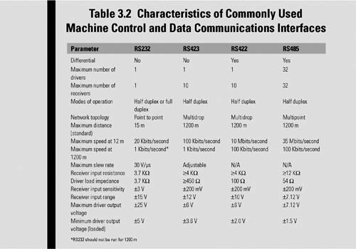
Noise in the signals carried on the cable is reduced by twisting the signal lines and providing an overall shield around the pairs of cables. External sources will induce noise currents that are then reversed at each twist of the wire pairs. This approach cancels the induced noise and improves the integrity of the data signals on the end-to-end run of the cable.
There are additional improvements when using RS422 over RS232 besides just the maximum data speed and overall cable length. RS232 was specifically defined as an interface between computers, printers, and terminals with modems. Modems would translate the communication signals to protocol acceptable for long-distance communication (i.e., a device was located on the other side of the control room or building). RS422 allows the direct connection of intelligent devices, without the need of modems. Where an RS232 line driver is only designed to serve one receiver, a RS422 line driver can serve up to 10 receivers in parallel, allowing one central control unit to send commands in parallel to as many as 10 slave devices. However, those slave devices are unable to send return information over a shared interface line.
RS422 allows a multidrop network topology rather than a multipoint network where all nodes are considered equal and every node has send and receive capabilities over the same line. Should a multipoint communication network be required rather than a multidrop, then implementation over RS485 is the better choice because it offers a maximum of 32 parallel send and 32 receive units on one communication channel.
Video Disk Recorder: Command and Control Specification
This specification was developed by Odetics Broadcast Corporation as a set of commands for the control videoserver and video disk devices. Grass Valley later extended the specification with a list of new and extended commands and called this new extended protocol Advanced Media Protocol (AMP).
Advanced Media Protocol
Advanced Media Protocol is an extension of the Odetics protocol, which is supported by videoserver manufacturers as a client application through external control devices connected via RS422 serial connectors or Ethernet network connections.
Control protocol support for clip and file names has been limited to 8 bytes, restricting users from creating realistic and practical names. AMP supports variable-length clip names, allowing lengths up to 64 Kbytes. The size of the clip name is, thus, limited only by the capabilities of the videoserver platform. In a networked environment, commands can be issued through the network using protocols such as TCP/IP, IPX, RPC, etc.
Ethernet access is possible using DCOM or sockets on the Profile XP platform. Interfacing with sockets is similar to interfacing with DCOM, requiring only that the send and receive functionality be changed from DCOM send/receive units to sockets send/receive units.
AMP Client applications run in modes such as protocol control- only mode (where a Grass Valley Profile XP channel is controlled by a remote third-party application and the local AMP Client application only monitors activities on the channel); local and protocol control mode (where a channel can be controlled by either the local AMP Client application or the third-party applications such as a hardware controller or a software application); active clip (where the AMP “preset id” is considered the active clip that controls channel resources); or preview clip (where the AMP “preview preset id” is considered the preview clip).
EVS AVSP
EVS AVSP is a protocol developed by EVS Broadcast Equipment of Belgium for the control of their suite of videoserver and video disk replay systems. The data rate is 115.2 Kbits/second via a serial control over RS422, with Ethernet control in its future.
Thomson DD 35
Thomson DD35 is a serial control protocol utilized in Thomson production switchers for interfacing with clip stores, replay systems, and video disks.
Further Readings
SMPTE 305M-2005 (Revision of SMPTE 305.2M-2000)
A standard that specifies a data stream protocol used to transport packetized data. The data packets and synchronizing signals are only compatible with 10-bit operation of SMPTE 259M and are generally carried over a coaxial cable physical material using BNC connectors. The protocol parameters are compatible with the 4:2:2 component SDI format. The data stream uses the digital television active line for the payload. Ancillary data packets, defined by SMPTE 291M and set in the horizontal blanking interval are used to identify the payload application. The payload data may be organized in fixed-length blocks or variable-length blocks.
SMPTE 338M–2005 (Revision of SMPTE 305.2M–2000)
The High Data Rate Serial Data Transport Interface (HD-SDTI) is a compatible (with SMPTE 305M) standard that provides the mechanisms necessary to facilitate the transport of packetized data over a synchronous data carrier. The HD-SDTI data packets and synchronizing signals provide a data transport interface compatible with SMPTE 292M (HD-SDI) and can readily be used by a coaxial cable-based infrastructure.
The SMPTE 338M standard uses a dual-channel operation with each line carrying two data channels each forming an independent HD-SDTI data transport mechanism. The two channels are word multiplexed onto a single HD-SDI stream with one line channel occupying the C (chroma) data space and the other line channel occupying the Y (luminance) data space that would be applicable in the carriage of baseband high-definition video. It should be understood that users may only carry one form of information at a time. If transporting as data, video may not also be carried at the same time.
This implementation provides for a baseline operation that supports a constant payload length per line channel with a maximum payload data rate up to approximately 1 Gbits/second.