
One of the problems with doing visual effects for feature films is that the client is steeped in film formats and nomenclature but the poor digital artist is only exposed to pixels. The process is so digital now that you can go through an entire visual effects career and never see or touch a real piece of film. Added to this lack of exposure is the fact that film has a great many different formats, some even with non-square pixels. The main purpose of this chapter is to describe the most common film formats you are likely to encounter, what they are used for, their aspect ratios, and their scanned image resolutions. Along the way it is hoped you will also pick up some film terminology.
If you are going to work on 35mm feature film visual effects you should know a few key facts about film beyond that it runs at 24 frames per second—such as there are 16 frames per foot and that there are 90 feet of film per minute. Yes, film people count the length of a shot not in runtime or frame count, but in feet and frames. For example, a 5-second shot would have 120 frames to you and me, but to a film person this shot is 7 feet and 8 frames long.
Fitting widescreen films into the 1.33 aspect ratio of SDTV screens has never really worked very well, but it is still important to know about the various approaches that are used to letterbox and “pan and scan” a film for video. While you may think of title safe as a video issue, if you ever work on titles for film someone is going to ask you if they are 4 by 3 safe. Hopefully you will have read the title safe section of this chapter before that happens. We will also take a look at how film is digitized to create those digital files for your visual effects shots and how they are recorded back out to film.
The last section examines the Digital Intermediate (DI) process and what it means to you as a digital compositor. The DI process actually “wraps around you,” meaning that the film frames you work on will probably be digitized by the same DI facility that your finished work will be delivered to. It will therefore behoove you to know something about them, their process, and how your work fits into it.
12.1 CAPTURE Vs. DISPLAY FORMATS
When a cinematographer (a.k.a. Director of Photography, or DP, or DoP) looks through the viewfinder of his film camera he sees the entire scene as it is being captured on the film. This is the camera aperture. He also sees a ground glass outline of the intended display format of the film—that is to say, what portion of the frame will be projected in the theater. This is the projection aperture. An example of what the cinematographer sees in the viewfinder is shown in Figure 12-1. The cinematographer carefully composes the shot so that the item of interest is always contained within the projection aperture since that is what we will ultimately see in the theater.
This issue of the capture format (camera aperture) vs. the display format (projection aperture) is unique to film. With video the camera captures only and exactly what will be displayed on TV. Not so with film. The exposed film frame is almost always larger than the final displayed image in the theater, and there are differences between the various camera apertures and the various projection apertures. Understanding these differences is a key part of working with film.
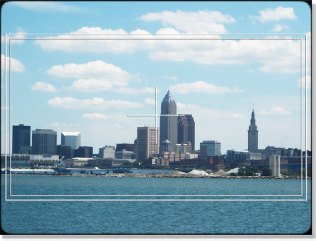
Figure 12-1 The view through the viewfinder
When film is digitized the entire camera aperture is normally scanned and delivered to the compositor, and there are several different camera apertures that might be used for photography and scanning. When working on the visual effects shot the camera aperture is not the most important thing. What is most important is the “safe-to” aperture. This is the projection aperture that the visual effects must be made safe to—that is, everything inside this aperture must be done perfectly, and everything outside of it can be ignored. The safe-to aperture might be the same as the projection aperture or it might be different—and different is always wider, and wider means more work. This can have a major impact on how much work and cost will go into each shot, so it is very important to get clear at the start of a project. The client must be asked to go on record and declare the safe-to aperture for all the visual effects shots.
12.2 ACADEMY AND FULL APERTURE
A 35mm film frame can be exposed using one of two primary camera apertures—academy aperture or full aperture—and the film scans you get could be from either format. Which format the camera records is controlled by a metal plate in front of the film with a rectangular hole cut in it called the aperture. Full aperture (Figure 12-2) exposes the image from perf to perf—the little holes used to sprocket the film through the camera called perforations. You can see how the image spans four perfs and completely fills the frame with just a thin black frame line above and below to separate it from the next frame. This exposes the maximum film area, has an aspect ratio of about 1.33, and is now referred to as “super 35,” a more hip and modern term than “full aperture.”
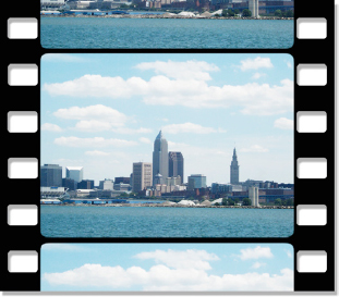
Figure 12-2 Full aperture
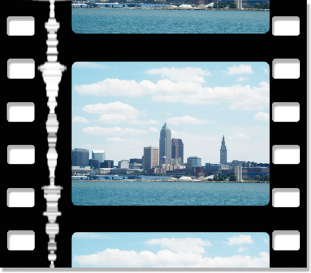
Figure 12-3 Academy aperture
In the days before Dolby Digital Surround Sound 7.1 with Mega Joule Quadraphonic Audio Blasters the sound track was simply printed on the projection film right alongside the picture like the example in Figure 12-3 (the white squiggles to the left of the image are the sound track). In order to leave room on the film for the sound track the picture area had to be squeezed over to the right and made about 10% smaller than the full aperture frame, but still devoted four perfs per frame. In those days the camera aperture was also academy so the exposed film matched the projected film. Compare the image size of the academy aperture with the full aperture, which has 33% more pixels. An academy aperture scan has an aspect ratio of about 1.37, but both academy and full aperture are referred to as “1.33”—even though they aren’t.
When film first started to be digitized at Kodak’s Cinesite facility in Hollywood way back in 1992 most of the film footage being digitized was academy. Over time the practice has shifted to shooting the movie as super 35 (full aperture). The larger image area of super 35 reduces the grain size and makes for a sharper picture. The resolution of a full aperture scan is 2048 × 1556 and is referred to as a “2k” scan. For an academy aperture the film scanner’s optics scan the same full aperture area at the same resolution, but only write to disk the academy area, which results in an 1828 × 1332 scan. It is as though the film scanner scanned the full aperture frame then cropped it to the academy aperture. As a result, both formats have the same number of pixels per square millimeter of film.
You may actually never see an academy film scan in your digital compositing career, but you might need to make one. The super 35 format is fine for principal photography (shooting the movie) and doing visual effects, but before it gets to the theater it must be converted to an academy aperture in order to fit the theater projector. In some cases you may be given a super 35 scan to do a visual effects shot, but the deliverable format might be an academy aperture. If you simply scale the super 35 scan from 2048 × 1556 down to the academy size of 1828 × 1332 you will have imparted a small 4% horizontal stretch to the results because their aspect ratios are not identical. You might want instead to crop the super 35 image to a 1.37 aspect ratio, and then scale it down to academy (1828 × 1332).
12.3 PROJECTION FORMATS
Within the academy and full aperture capture formats there are several projection formats. The film projector in the theater also has a metal plate with a rectangle cut in it called an aperture that the film projects through. This masks off the film to its projection aspect ratio regardless of the size or shape of the image on the print. Of course, only academy prints go to the projector, but when working on the super 35 film scan you will need to know what the projection format is so you can work within it on the super 35 version. Later the super 35 frame will be sized down to academy for projection.
There are standard guides called camera guides that draw white rectangles over the scanned film frame to show where the various projection apertures are. When you work on a film job you need to know what projection aperture to work to so you can compose your shots correctly. This is a critical piece of information for the entire show and must be confirmed by the client before any work is done. Following are the three most common projection formats you will encounter. They are illustrated for super 35 in Figure 12-4 and for academy in Figure 12-5. (To view a high resolution version of the film camera guide see www.compositingVFX.com/CH12/Figure 12-4.tif)
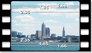
Figure 12-4 Super 35 camera guide
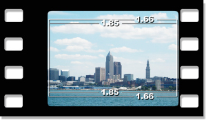
Figure 12-5 Academy camera guide
In the super 35 format, the inside-most camera guide is the 2.35 aspect ratio which will be cropped out of the frame then squeezed horizontally and stretched vertically to make an anamorphic Cinemascope frame that goes to the film recorder. This is referred to as a “scope extraction” because it is extracting the Cinemascope window from the super 35 frame. The procedure is to crop a 2048 × 872 window out of the super 35 frame and resize it to 1828 × 1556. There is more about the Cinemascope film format in section 12.4 below. The 2.35 aspect ratio camera guide is only used on super 35 film. You will notice it is absent from the academy camera guide in Figure 12-5. The reason is that the academy frame is just too small to resize to 2.35. It just isn’t done.
12.3.2 1.85
The next camera guide is the 1.85 projection aperture. This is the American definition of widescreen. The most common scenario is to be given a super 35 film scan to work with, but told that the film format is 1.85.
12.3.3 1.66
The 1.66 aspect ratio is what Europeans consider to be widescreen. Its significance to the red-blooded American compositor is that even though you may be working on a show to one of the other formats, you will often make your work “safe to” the 1.66 format. This means that even if your show is a 1.85 format your work (matte lines, dust-busting, garbage mattes, etc.) must be good out to the 1.66 line because when your movie goes to Europe (and they all go to Europe) it will be projected out to 1.66. The one exception is if the format is 2.35. In this one case you know that the picture outside of the 2.35 window is going to be cropped and thrown away when the scope extraction is done, so no sense wasting time making it pretty out there.
12.4 CINEMASCOPE
Cinemascope (or “Cscope” or “scope”) is a very unusual film format. Not uncommon, just unusual. It is both a capture format and a projection format. In other words, it is the one film format that projects in the theater exactly what is seen on the original camera negative. The basic idea is that filmmakers wanted a very widescreen image projected in the theater. If you tried to crop a wide image out of the middle of an academy frame and just blow it up to fill the wide screen it would look soft and lacking in detail. To get more picture detail you have to use more of the negative. The solution that filmmakers came up with was to expose the negative from top to bottom just like full aperture, but use an anamorphic lens on the camera that squeezes the image horizontally by 50% to fit it within academy to leave room for the sound track. The resulting anamorphic film frame is shown in Figure 12-6.
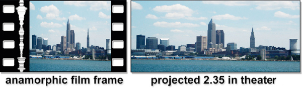
Figure 12-6 How Cinemascope images work
When it is time to project the film in the theater the projector has another anamorphic lens that stretches the image horizontally by a factor of 2, exactly canceling out the squeeze on the film frame. This results in a projected image with a 2.35 aspect ratio like the example in Figure 12-6. This arrangement uses twice the amount of negative than simply cropping the 2.35 out of the academy aperture. Note that the exposed film area of the anamorphic film frame is much taller than the normal academy aperture frame shown back in Figure 12-3. A Cscope film frame that was photographed anamorphically has the width of an academy aperture but the height of the full aperture. (To view a high resolution version see www.compositingVFX.com/CH12/Figure 12-6.tif)
In today’s film slang the term “2.35” is synonymous with “Cscope.” However, one technical footnote here is that 2.35 is now actually 2.40. The top and bottom of the frame are now shaved just a wee bit when projected in the theater. Rumor has it that this was done to leave a little more room at the black frame line at the top and bottom of each frame of the negative for splicing. Seems that the splices were showing up on the screen when projected. Not good. The potential confusion here is that some folks will actually have the nerve to use the technically correct term “2.40” to refer to Cscope rather than the traditional term “2.35.”
The problem with digital compositing and anamorphic frames is that the pixels are not square (they have an aspect ratio of 2.0), and we saw what a migraine that was with video. For many operations, such as keying and color correction, the anamorphic image can be left “squeezed.” However, for any transformations such as rotate, scale, and skew the image must first be “flattened” to restore square pixels, just like video. There are some compositing programs intelligent enough to recognize the anamorphic images and compensate internally so the image does not have to be flattened. It also must be flattened before any motion tracking—unless you have one of the real smart motion trackers that knows about anamorphic images. A typical anamorphic scan will be 1828 × 1556, so when it is flattened it suddenly balloons to 3656 × 1556, a very large image indeed that will tax even the mightiest workstation.
The good news here is that Cinemascope photography is getting less and less popular thanks to the digital intermediate process, which we will look at later in this chapter. Cinemascope photography is difficult because the anamorphic lenses are large, expensive, degrade image quality, and are hard to work with. With the digital intermediate process the film is now photographed in super 35, and then the digital “scope” extraction described above is done in the DI suite before it is sent to the film recorder. It is recorded as an anamorphic image on film, even though it was originally shot “flat.” The digital scope extraction works just fine and produces a nice crisp image with none of the pain of working with anamorphic lenses. As a result, shooting super 35 and doing a scope extraction is all the rage in Hollywood.
12.5 VISTAVISION
VistaVision is occasionally used as a visual effects format but is no longer projected in the theater, so it is now a capture format only. As you can see in Figure 12-7, the “vista” frame spans 8 perfs and is huge compared with the super 35 4-perf frame. All this extra negative is used to photograph visual effects elements in very high detail which can then withstand a great deal of abuse by the digital compositor. Regions can be cropped out and blown up or a digital camera can pan around the frame in a process called a post move (a camera move done in post) without the image quality breaking down. A vista frame is also what you get with a 35mm photography camera, so sometimes stills will be shot and used for visual effects shots.
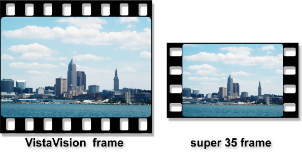
Figure 12-7 Comparison of VistaVision frame size to super 35
The odd thing about vista frames is that they are actually lying on their sides. The 35mm film is put through the camera horizontally, so when the film is held up next to normal 35mm film the image is sideways. If you rotated the VistaVision frame in Figure 12-7 by 90 degrees and placed it below the super 35 frame you would find their widths to be the same. A typical 2 k vista scan will be 3072 × 2048 producing an aspect ratio of 1.5. The vista frame has exactly twice the negative area of the super 35 frame.
12.6 3-PERF FILM
Here’s trouble—3-perf film is a capture format only that is exactly what it sounds like—there are 3 perfs of 35mm film for each frame instead of the normal 4 perfs. It is the exact same 35mm film stock that is used in regular film cameras that is simply loaded into special film cameras that advance each frame of film 3 perfs instead of the usual 4. It was originally invented because it reduced the amount of 35mm film consumed by 25% when shooting a movie. Since 35mm film is expensive, this was a significant savings.
Met with enthusiasm when it was first introduced, the fun died down when it was realized how many difficulties it introduced into the film post-production process. Why I said at the top that 3-perf is trouble is because it creates editorial confusion, which becomes shot length and timing confusion for you at compositing time. The reason is that film editorial measurements are based on feet and frames: 4-perf film has 16 frames per foot but 3-perf has an awkward 21⅓ frames per foot. You actually have to use a full 3 feet of film just to come out to an even number of frames (64).
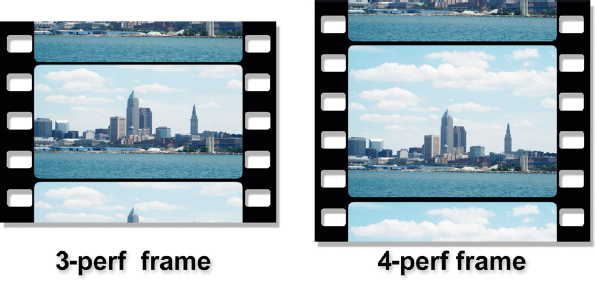
Figure 12-8 Comparison of 3-perf frame to 4-perf frame
However, recent technological advances have caused a resurgence in 3-perf film and you are sure to run into it soon. The two main influences that have resuscitated 3-perf film are the digital intermediate process and HDTV. The digital intermediate process eliminates many of the troubling aspects of working with 3-perf once the film is digitized since it becomes a digital file like any other and easily converted to a common projection format like 1.85 or 2.35. The reason HDTV helped is if you are shooting 35mm film for an HDTV finish (such as a quality television show) the 1.75 aspect ratio of 3-perf film is very close to the 1.78 aspect ratio of HDTV and makes a superb capture medium that costs 25% less than using standard 4-perf 35mm film. A 3-perf scan will be 2048 × 1168.
12.7 70MM FILM
There are a few film scanners that can scan 70mm film so there is definitely a slim chance that you could run into it. It is both a capture format and a display format. A 70mm film frame spans 5 perfs rather than the 4 of super 35 so it is often referred to as “5 perf 70.” The 4096 × 1840 scan has an aspect ratio of 2.2 and the film frame is huge compared with 35mm as you can see in Figure 12-9. In truth, the camera negative is actually only 65mm wide. When the film goes to theatrical print it is printed on 70mm wide stock with the extra width outside of the perfs to make room for multiple sound tracks, so the actual image sizes are identical. Because of these two different sizes you may also hear this format referred to as “65/70.”

Figure 12-9 Comparison of 70mm film to 35mm film
12.8 SUPER 16 FILM
Kodak has recently introduced a number of new 16mm film stocks to breathe new life into the super 16 film format, so you could run into this. There are two situations where super 16 makes good production sense. One is as a film capture instead of video capture for an HDTV show. Its 1.66 aspect ratio frame can be trimmed slightly during telecine to become a good fit for the 1.78 of HDTV. The other situation is for a real low-budget film that cannot afford 35mm film. A comparison of their frame sizes is shown in Figure 12-10.

Figure 12-10 Comparison of 16mm film to 35mm film
Since 16mm and 35mm films are made out of exactly the same plastics and emulsions, the only real difference in image quality is the film grain. Since the super 16 frame is half the size of the 35mm frame the grain is twice as big, so the new stocks Kodak has introduced have a much smaller grain structure. However, super 16 has but one lonely perf per frame. This means that it is prone to gate weave when photographed and again when scanned. This means that it is not very good for visual effects since the scanned layers would “squirm” against each other. However, with some image stabilizing they can be made serviceable.
12.9 FITTING FILM INTO VIDEO
As we saw in Chapter 11, film and SDTV do not play nice together. The frame rate problems are solved with a 3:2 pull-down, but there is still the question of the shape of the screen. SDTV is nearly square with its 4 × 3 (1.33) aspect ratio while film can have a much wider screen with aspect ratios from 1.85 to 2.35. In this section we will examine the various solutions to this mismatch between the shape of the video and film pictures and how to format film titles so they will be compatible with the video version of the movie.
12.9.1 Letterbox
The letterbox format is one of the most common solutions to fitting a widescreen movie into an SDTV 4 × 3 video frame. This format is also referred to as “fit side-to-side.”The example on the left side of Figure 12-11 illustrates a 1.85 movie in letterbox format. The widescreen film frame is “padded” top and bottom with black until the aspect ratio of the frame matches the video. This has the unfortunate effect of shrinking the movie down to where your personal film credit might be hard to read. A true cinematic tragedy.
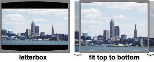
Figure 12-11 Letterbox vs. fit top to bottom
The other solution is to fit the widescreen movie top to bottom in the video frame and simply lose the left and right sides of the picture as shown on the right side of Figure 12-11. The lost parts of the picture are indicated by the curly brackets along the bottom edge. While this rarely loses enough picture area to bother the viewer, the director and cinematographer might be apoplectic about the loss of their original 1.85 composition along with their “artistic intent.”
HDTV’s aspect ratio of 1.78 is very close to film’s 1.85 so you could fit the film into HDTV by trimming just a bit off the top and bottom of the film frame. If the movie were a 2.35, however, it might have to be letterboxed.
12.9.2 Pan and Scan
For a very widescreen film format such as 2.35 the letterbox format can shrink the movie to truly tiny proportions. One solution is to fit the movie top to bottom, then shift the picture left and right as the action requires in a technique called “pan and scan.”
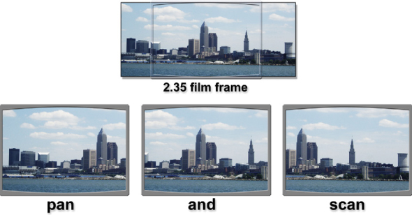
Figure 12-12 Using pan and scan on a 2.35 widescreen film frame
The top image in Figure 12-12 represents the original 2.35 film frame with a typical 4 × 3 video monitor superimposed for a size comparison. A great deal of the wide-screen image will be lost if things are left this way. The bottom series of pictures illustrate how the entire panoramic shot might be salvaged by panning the image from right to left. This can get a little disorienting if the scene is a two-shot with one person on the left and the other on the right and the camera is whipping left, then right, then left to follow the conversation. A pan and scan like this might even be done on a 1.85 film if the action seemed to warrant it.
12.9.3 HTDV
As it was pointed out in the previous chapter, HDTV was designed to be a much better fit for feature film. The standard American theatrical widescreen format is 1.85, which is very close to HDTV’s aspect ratio of 1.78. You could either shave a few pixels off the ends of the 1.85 film frame to fit it into 1.78 (fit top-to-bottom) or it could be formatted in letterbox like the example in Figure 12-13 (fit side-to-side) with just a thin strip of black at top and bottom. A Cinemascope film with a projection aspect ratio of 2.35 in letterbox format is shown on the right.
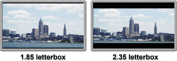
Figure 12-13 Feature film letterboxed into HDTV
12.9.4 Title Safe
In Chapter 11, Working with Video, we saw how to make a title safe guide for SDTV and HDTV video. In the course of film work it may come to pass that you will have to make some titles. Film does not have a title safe industry practice per se, but when the film goes to video (which they always do) then it may be necessary for the titles to be title safe for the 4 × 3 pan and scan version. For you to do that you will have to know where the 4 × 3 title safe is within the film frame.

Figure 12-14 How to create a 4 × 3 title safe guide
Let’s say you have some nice 2 k super 35 film scans like the example in Figure 12-14 and the show format is 1.85. Draw a 4 × 3 box (a 1.33 aspect ratio rectangle) that fits top-to-bottom within the 1.85 camera guide. Make a copy of the 4 × 3 box and scale it by 0.8 to make the 4 × 3 title safe rectangle you see in Figure 12-14. This is the 80% guide we saw in the Title Safe section on page 211 of Chapter 11. By keeping the titles within the 4 × 3 title safe rectangle they will be title safe when the film is transferred to SDTV video. If the show is going to SDTV in letterbox format then this is not an issue. However, the letterbox format will shrink the text size a great deal, so a larger font might need to be used that will be readable in letterbox. Either way, do make sure that you get the client’s decision on this in writing.
12.10 DIGITIZING FILM
The film is digitized by a large and expensive machine called a film scanner, with a lovely example of a Spirit 4 k scanner in Figure 12-15. (To view a high resolution version see www.compositingVFX.com/CH12/Figure 12-15.tif) Each camera roll (the rolls of film exposed in each day’s shoot) is typically 400 feet long and contains many shots, but only a few are actually used. The developed camera rolls are mounted on the film scanner and it is told not only which shots to scan, but also exactly which frames from those shots to scan. Because film scanning is still expensive only the frames actually needed for the movie are scanned—plus a few extra frames on both ends known as “handles.” The latest film scanners can actually scan film in real time—that is, a two-hour movie only takes two hours to scan. However, since the scanning process must be halted for each camera roll to be mounted onto the scanner the process actually takes several days.
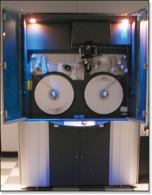
Figure 12-15 Film scanner
The finished scans that you receive are typically 2 k in resolution, but film scanners usually scan the film optically at 4 k resolution, and then resize the raw 4 k scan down to 2 k for final output. A 4 k scan resized down to 2 k is a better scan than a straight 2 k scan. Some film scanners actually optically scan the film at 6 k, while others are actually less than 2 k and resize the image up, and then apply an image sharpening operation to cover up the low resolution scan. Needless to say, if you are the one getting the film scanned, be sure to find out what the optical scanning resolution is because it is usually different than the delivered resolution.
The 2 k film scans will be 10-bit log data in either a DPX or Cineon file format. The two formats are very similar—indeed, the DPX file format is a considerably expanded and modernized version of the older (and fading from existence) Cineon files. They both contain the same 10-bit log data so images in either file format will look identical. The pertinent question now is what is this “log data” that film scans come in and how do you work with it?
12.11 LOG FILM DATA
The log film data story is both lengthy and complex and in an introductory book like this the tale needs to be kept short and uncomplicated. However, there is much useful information about log data that would benefit the budding compositor without getting too hung up in our exponents.
If you have ever seen a piece of developed negative you may have noticed how the image looks low contrast, thin, and washed out compared with the print that is made from it—whether its a paper print, a theatrical print, or a slide. Log data is a scan of that negative so it has a similar appearance. Figure 12-16 is a classic test pattern that Kodak distributes for calibrating film equipment that is displayed here as its original log data (thank you, Kodak). It, too, is low contrast, thin and washed out like the negative it came from. (To view a high resolution version see www.compositingVFX.com/CH12/Figure 12-16.tif) The reason it looks so ugly is that we have not made a “print” of it yet. The process of making a print dramatically increases the contrast, density and color saturation until it looks more like Figure 12-17.
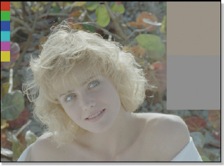
Figure 12-16 Log image

Figure 12-17 Print of the log data
The log image in Figure 12-16 is what would be sent to the film recorder to film out as a new negative. It is also how the picture looks when working with log data on feature film visual effects and how the finished effects shots would be delivered. Of course, in a proper setup the workstation monitor has a special “print LUT” that displays the log data as it appears in Figure 12-17, which is also how it will appear when the print is projected in the theater. In other words, the workstation monitor LUT displays the log data with a “simulation” of how it will look when printed and projected in the theater.
With normal image data like video, CGI elements, and digital matte paintings the data is linear, not logarithmic. This means that the data represents the brightness of pixel values. With log data, however, the data represents the exponents of the brightness of pixels, not the brightness directly. This fact completely changes the math required when performing composites and color correction. As a result, log data is difficult to work with, so it is shunned by some and mishandled by others. The reason that filmmakers want you to put up with log data is that it can represent very high dynamic range images without clipping, just like film. This is something that normal linear data cannot do.
However, there is another approach looming on the horizon, which we saw in Chapter 2, Digital Images, and that is the EXR image file format. It is unique among file formats in that it is both linear and has an extended dynamic range. In fact, it was specifically developed for working with feature film scans without resorting to log data. I expect that eventually EXR will take over the feature film visual effects world and no one will have to suffer the labor of log anymore.
12.12 RECORDING FILM
Digital images get put back out to film using a large and expensive machine called a film recorder, with a classic example of an Arri film recorder in Figure 12-18. (To view a high resolution version see www.compositingVFX.com/CH12/Figure 12-18.tif) The 2k frame files are typically loaded onto a nearby disk array that has a dedicated high-speed network connection to the film recorder. The digital frames are read from the disk array one at a time and exposed to film. Film recorders are not yet as fast as film scanners. The hot new ones lope along at a few frames per second, so they run at around eight times real time. However, the technology in this industry moves rapidly so we can look forward to real-time film recorders soon.
There are two basic technologies used by film recorders. One is CRT based where the picture is filmed off an incredibly high-quality monitor. The other technology is laser based where the image is “painted” directly on the raw film negative by sweeping red, green, and blue lasers. Some new machines use LEDs instead of lasers. Because the laser-based systems provide such a pure, sharp, and intense light source they tend to be faster, produce sharper images, and have better color separation (saturation) than the CRT type of film recorders. They can also use a finer grained film than CRT systems because they have such high-intensity light sources. This is not to say that CRT film recorders don’t do a good job or that new models coming online aren’t getting better. This is to say that if you are selecting a film recording service, do some test filmouts and project them.
In times of yore the finished visual effects shot was shot out to film and the digital negative was delivered to the client to be cut into the movie. Today, the digital files are much more likely to be delivered to the DI facility to join their neighbors on the timeline of the digital color corrector, so we will now take a look at the DI process.

Figure 12-18 Film recorder
12.13 THE DIGITAL INTERMEDIATE PROCESS
The Digital Intermediate (DI) process color corrects the entire feature digitally in a computer instead of chemically in a film lab. The changeover to DI has swept through Hollywood like a tornado. Once it caught on, everybody had to have it. Some directors require the promise of doing a DI for their movie as part of their contract with the studio. Many of the studios have built their own DI facilities. The reason why it is so popular is that it grants the filmmaker’s biggest wish—more creative control. Here is a Hollywood film fact—no director or cinematographer that has done a DI has ever wanted to go back. But go back to what? Before we begin a tour of the DI process we need to understand the conventional workflow that it has replaced—what is now referred to nostalgically as the “wet” process.
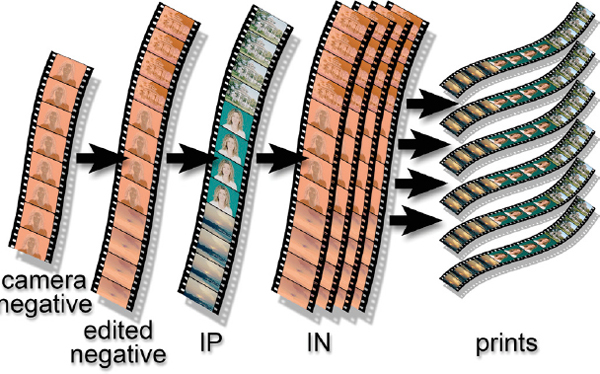
Figure 12-19 Conventional film post production
The conventional film post-production process is depicted in Figure 12-19. It is referred to as “wet” because it entails exposing and developing a couple of generations of the film in a lab with all their tubs and vats of developers and baths and rinses. The post-production process encompasses three main objectives—producing an edited version of the movie, color correcting each shot, and creating a master to strike all of the theatrical prints. These multiple generations of the film are made with special intermediate film stocks, so named because they are intermediate between the camera negative and the theatrical prints.
12.13.1 Editing the Film
Today, movies are edited on video. The camera negatives are transferred to video in telecine, and then the editor “cuts” (edits) the movie using this video. Problem is, when it is done, the editor has an edited video, not an edited film. The next step is to “conform” the film to the video, where each clip of film is matched to each clip of video, and then the precious and irreplaceable camera negative is cut to match. The camera negative is cut into pieces by a negative cutter (yes, there is a special guy or gal just to cut the negative) and then spliced together to form the edited negative (see Figure 12-19), the film version of the edited movie.
12.13.2 Color Correcting
Once the edited negative is ready it is taken to a film lab for color timing, which is film speak for color correcting. When the various shots are first cut together they vary from shot to shot in brightness and color. One is too dark, the next too cyan, the next too bright, etc. This makes for jarring viewing so the shots must all be color corrected in order for them to play together nice. The edited “neg” (short for negative) is put on a machine that allows control of red, green, and blue light sources so the brightness and color can be adjusted on a shot-by-shot basis to expose another piece of intermediate film. Since we are color timing from a negative, the resulting color-timed intermediate piece of film is a positive, or IP, short for interpositive. We now have the color-timed IP shown in Figure 12-19.
12.13.3 The Print Master
It is a film fact that when you duplicate a piece of film you get a negative of the original. In order to strike the theatrical prints, which must be positives, we will obviously need to use a negative. But we don’t have a negative. The color timing process above left us with the color-timed IP, which is a positive. We are going to have to make a copy of the IP in order to make a negative in order to strike the prints. This negative will be made on another intermediate film stock and will be called the internegative, or IN, also shown in Figure 12-19.
Rather than being a wasted duplication step just to get a negative, the IN step is actually a good thing. The reason being that it takes a lot of time and money to make the color-timed IP and you do not want to ruin it by running it thousands of times on a film printer to make the thousands of prints that go out to the theater. It is much better to take the one expensive IP and make several cheap INs, then put the expensive IP in a safe place and use the cheap INs to make the thousands of prints. If an IN gets eaten by the film printing machine, just throw it away and get a new one. No worries.
12.13.4 How DI Works
Now that you are an expert on the wet process of color timing a feature film we can contrast that with the new and improved Digital Intermediate process, following the diagram in Figure 12-20. The first and very important difference is that we are not going to chop up the precious and irreplaceable camera negative. As we saw in section 12.10 Digitizing Film, the entire camera roll is placed on the film scanner and the selected frames are scanned, leaving all of the camera rolls in tact and uncut. While depressing to the negative cutter’s union, this is a great relief to the director, cinematographer, and movie producers.
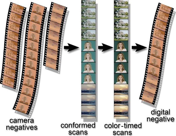
Figure 12-20 Digital Intermediate film post-production
The movie can now be conformed (edited to match the video) by simply placing the scanned frames in the right order on the timeline of the digital color corrector. This is the DI replacement for the edited negative in the wet process. Next the conformed scans are color corrected, or color timed, by a talented colorist. He must be talented because he is paid 10 times as much as you or me. This produces the color-timed scans in Figure 12-20 and is the DI replacement for the color-timed IP in the wet process.
The last step is to send the conformed and color-timed film frames to the film recorder to be exposed back to film. This produces the digital negative in Figure 12-20. Since this is filmed out using an intermediate film stock, this piece of film is in fact the digital intermediate for which the entire DI process is named. It is also the DI replacement for the IN in the wet process.
You may recall from the conventional process diagram (Figure 12-19) that several INs were needed to strike the thousands of prints, but we have produced only one here. Today it costs tens of thousands of dollars to film out one IN, so it is not practical to film out 5 or 10 of them. The one IN is taken to a film lab which dups it to an IP, then from there to several INs, and from those the thousands of prints are struck.
The real win here is the enormous creative control over the color correction that is possible in the DI suite with a digital color corrector compared with the wet process in the film lab. The wet process has only a few simple color correcting capabilities while the digital kind is virtually limitless. In addition to that, the DI suite offers unique image processing capabilities such as grain reduction, dust-busting, speed changes, image sharpening, and scene salvage, to name just a few.
When a movie is color timed with the wet process it produces the finished film, but not the video version. For that the movie must be separately transferred to video on a telecine and color timed a second time for video. When a movie uses the DI process the color-timed digital frames are laid off directly to HDTV video as the 24P master we saw in Chapter 11, and from that all other video variants are easily created. The DI process therefore produces both the film and video masters, so some refer to it as Digital Mastering. If the movie is slated for a Digital Cinema showing, the D-Cinema version is also made directly from the color-timed digital files.
12.13.5 DI and You
So why does the modern digital compositor care about this DI process anyway? Because it has a direct effect on the visual effects shots that you will be delivering to your client. The client will be reviewing your shots with some kind of real-time playback on some kind of workstation, or even QuickTime movies on his laptop, but the final deliverable will be 2 k log files sent to the DI facility of his choice.
The DI facility has a digital pipeline of its own and will have requirements for file formats, directory structures, and naming conventions that you will need to conform to. Basically, your work must move seamlessly from your digital pipeline to theirs. Contact them to get their specs and set up your job accordingly.
Another issue is the deep magic of working with log image data. This is tricky stuff that must be dealt with correctly or the color space of the delivered images will be embarrassingly messed up. One of the classic amateur mistakes is to convert all of the log images to linear, clipping them in the process, then converting the clipped images back to log. The colorist will spot this immediately. Worse than the prospect of reworking all of the shots, it reveals that whoever delivered the effects shots does not know what they are doing when working with film.
One last issue is perhaps the most important. When two or more layers are composited together and color corrected to match, there will always be small mismatches between the layers. In the DI suite the color timing process can “stretch” the composite causing the layers to “pull apart,” exaggerating the mismatches. This is one of the main reasons for the gamma-slamming tip in Chapter 9.
The important point made in Chapter 4 about color grading bears repeating here. One thing that should be done before any compositing on feature film scans is a “color grading” of the background plates. You cannot know what the final color timing look of the movie will be, of course. Color grading is just a basic color correction designed to generally balance the picture and fix any seriously off-color plates. Many of the scans will be over-exposed or too cyan, for example. If these are used as is and the composited layers are color corrected to match an off-color background, when the composite goes to DI it will be heavily color corrected, which increases the chances of pulling the layers apart. A basic color grading before compositing will ensure that the colorist will do a less severe color correction, thus reducing the chances of tearing your work apart.