5
MICROPROCESSOR PROGRAMMING CONCEPTS
In this chapter we provide the fundamental concepts of microprocessor programming. Typical programming characteristics such as programming languages, basics of assembly language programming, instruction formats, instruction set architecture (ISA), microprocessor instruction sets, and addressing modes are discussed.
5.1 Microcomputer Programming Languages
Microprocessors are typically programmed using semi-English-language statements (assembly language). In addition to assembly languages, microcomputers use a more understandable human-oriented language called high-level language. No matter what type of language is used to write programs, microcomputers understand only binary numbers. Therefore, all programs must eventually be translated into their appropriate binary forms. The principal ways to accomplish this are discussed later.
Microprocessor programming languages can typically be divided into three main types: machine language, assembly language, and high-level language. A machine language program consists of either binary or hexadecimal op-codes. Programming a microcomputer with either one is relatively difficult, because one must deal only with numbers. The architecture and microprograms of a microprocessor determine all its instructions. These instructions are called the microprocessor's instruction set. Programs in assembly and high-level languages are represented by instructions that use English-language-type statements. The programmer finds it relatively more convenient to write programs in assembly or high-level language than in machine language. However, a translator must be used to convert such programs into binary machine language so that the microprocessor can execute the programs. This is shown in Figure 5.1.
An assembler translates a program written in assembly language into a machine language program. A compiler or interpreter, on the other hand, converts a high-level language program such as C or C++ into a machine language program. Assembly or high-level language programs are called source codes. Machine language programs are known as object codes. A translator converts source codes to object codes. Next, we discuss the three main types of programming language in more detail.

FIGURE 5.1 Translating assembly or high-level language into binary machine language.
5.2 Machine Language
A microprocessor has a unique set of machine language instructions defined by its manufacturer. No two microprocessors by two different manufacturers have the same machine language instruction set. For example, the Intel Pentium microprocessor uses the code 03C316 for its addition instruction, whereas the Motorola 68020 uses the code 064016. Therefore, a machine language program for one microprocessor will not run on the microprocessor of a different manufacturer.
At the most elementary level, a microprocessor program can be written using its instruction set in binary machine language. As an example, the following program adds two numbers using the Intel Pentium machine language:
0110 0110 1011 1000 0000 0001 0000 0000
0110 0110 1011 1011 0000 0010 0000 0000
0110 0110 0000 0011 1100 0011
1111 0100
Obviously, the program is very difficult to understand unless the programmer remembers all the Pentium codes, which is impractical. Because one finds it very inconvenient to work with 1's and 0's, it is almost impossible to write an error-free program on the first try. Also, it is very tiring for a programmer to enter a machine language program written in binary into the microcomputer's RAM. For example, the programmer needs a number of binary switches to enter the binary program. This is definitely subject to error.
To increase the programmer's efficiency in writing a machine language program, hexadecimal numbers rather than binary numbers are used. The following is the same addition program in hexadecimal using the Intel Pentium instruction set:

It is easier to detect an error in a hexadecimal program, because each byte contains only two hexadecimal digits. One would enter a hexadecimal program using a hexadecimal keyboard. A keyboard monitor program in ROM, usually offered by the manufacturer, provides interfacing of the hexadecimal keyboard with the microcomputer. This program converts each key actuation into binary machine language in order for the microprocessor to understand the program. However, programming in hexadecimal is not normally used.
5.3 Assembly Language
The next programming level is to use assembly language. Each line in an assembly language program includes four fields:
- Label field
- Instruction, mnemonic, or op-code field
- Operand field
- Comment field
As an example, a typical program for adding two 16-bit numbers written in Pentium assembly language is as follows:

Obviously, programming in assembly language is more convenient than programming in machine language, because each mnemonic gives an idea of the type of operation it is supposed to perform. Therefore, with assembly language, the programmer does not have to find the numerical op-codes from a table of the instruction set, and programming efficiency is improved significantly.
An assembly language program is translated into binary via a program called an assembler. The assembler program reads each assembly instruction of a program as ASCII characters and translates them into the respective binary op-codes. As an example, consider the HLT instruction for the Pentium. Its binary op-code is 11110100. An assembler would convert HLT into 11110100 as shown in Table 5.1.
An advantage of the assembler is address computation. Most programs use addresses within the program as data storage or as targets for jumps or calls. When programming in machine language, these addresses must be calculated by hand. The assembler solves this problem by allowing the programmer to assign a symbol to an address. The programmer may then reference that address elsewhere by using the symbol. The assembler computes the actual address for the programmer and fills it in automatically. One can obtain hands-on experience with a typical assembler for a microprocessor by downloading it from the Internet.
5.3.1 Types of Assemblers
Most assemblers use two passes to assemble a program. This means that they read the input program text twice. The first pass is used to compute the addresses of all labels in the program. To find the address of a label, it is necessary to know the total length of all the binary code preceding that label. Unfortunately, however, that address may be needed in that preceding code. Therefore, the first pass computes the addresses of all labels and stores them for the next pass, which generates the actual binary code. Various types of assemblers are available today:
- One-Pass Assembler. This assembler goes through an assembly language program once and translates it into a machine language program. This assembler has the problem of defining forward references. This means that a JUMP instruction using an address that appears later in the program must be defined by the programmer after the program is assembled.
TABLE 5.1 Conversion of HLT into Its Binary Op-Code

- Two-Pass Assembler. This assembler scans an assembly language program twice. In the first pass, this assembler creates a symbol table. A symbol table consists of labels with addresses assigned to them. This way, labels can be used for JUMP statements and no address calculation has to be done by the user. On the second pass, the assembler translates the assembly language program into machine code. The two-pass assembler is more desirable and much easier to use.
- Macroassembler. This type of assembler translates a program written in macrolanguage into machine language. This assembler lets the programmer define all instruction sequences using macros. Note that by using macros, the programmer can assign a name to an instruction sequence that appears repeatedly in a program. The programmer can thus avoid writing an instruction sequence that is required many times in a program by using macros. The macroassembler replaces a macroname with the appropriate instruction sequence each time it encounters a macroname.
It is interesting to see the difference between a subroutine and a macroprogram. A specific subroutine occurs once in a program. A subroutine is executed by CALLing it from a main program. The program execution jumps out of the main program and executes the subroutine. At the end of the subroutine, a RET instruction is used to resume program execution following the CALL SUBROUTINE instruction in the main program. A macro, on the other hand, does not cause the program execution to branch out of the main program. Each time a macro occurs, it is replaced by the appropriate instruction sequence in the main program. Typical advantages of using macros are shorter source programs and better program documentation. A typical disadvantage is that effects on registers and flags may not be obvious.
Conditional macroassembly is very useful in determining whether or not an instruction sequence is to be included in the assembly, depending on a condition that is true or false. If two different programs are to be executed repeatedly based on a condition that can be either true or false, it is convenient to use conditional macros. Based on each condition, a particular program is assembled. Each condition and the appropriate program are typically included within IF and ENDIF pseudoinstructions.
- Cross assembler. This type of assembler is typically resident in a processor and assembles programs for another for which it is written. The cross assembler program is written in a high-level language so that it can run on different types of processors that understand the same high-level language.
- Resident assembler. This type of assembler assembles programs for a processor in which it is resident. The resident assembler may slow down operation of the processor on which it runs.
- Meta-assembler. This type of assembler can assemble programs for many different types of processors. The programmer usually defines the particular processor being used.
5.3.2 Assembler Delimiters
As mentioned before, each line of an assembly language program consists of four fields: label, mnemonic or op-code, operand, and comment. The assembler ignores the comment field but translates the other fields. The label field must start with an uppercase alphabetic character. The assembler must know where one field starts and another ends. Most assemblers allow the programmer to use a special symbol or delimiter to indicate the beginning or end of each field. Typical delimiters used are spaces, commas, semicolons, and colons:
- Spaces are used between fields.
- Commas (,) are used between addresses in an operand field.
- A semicolon (;) is used before a comment.
- A colon (:) or no delimiter is used after a label.
5.3.3 Specifying Numbers by Typical Assemblers
To handle numbers, most assemblers consider all numbers as decimal numbers unless specified otherwise. All assemblers will also specify other number systems, including hexadecimal numbers. The user must define the type of number system used in some way. This is generally done by using a letter before or after the number. For example, Intel uses the letter H after a number to represent it as a hex number, whereas Motorola uses a $ sign before the number to represent it as a hex number. As an example, 60 in hexadecimal is represented by an Intel assembler as 60H and by a Motorola assembler as $60.
Typical assemblers such as MASM32 require hexadecimal numbers to start with a digit (0 through 9). A 0 is typically used if the first digit of the hexadecimal number is a letter. This is done to distinguish between numbers and labels. For example, typical assemblers such as MASM32 will normally require the number F3H to be represented as 0F3H; otherwise, the assembler will generate an error. However, ide 68k assembler used in this book for assembling 68000 and 68020 assembly language programs does not require ‘0’ to be used if the first digit of a hexadecimal number is a letter.
5.3.4 Assembler Directives or Pseudoinstructions
Assemblers use pseudoinstructions or directives to make the formatting of the edited text easier. Pseudoinstructions are not translated directly into machine language instructions. They equate labels to addresses, assign the program to certain areas of memory, or insert titles, page numbers, and so on. To use the assembler directives or pseudoinstructions, the programmer puts them in the op-code field, and if the pseudoinstructions require an address or data, the programmer places them in the label or data field. Typical pseudoinstructions are ORIGIN (ORG), EQUATE (EQU), DEFINE BYTE (DB), and DEFINE WORD (DW).
ORIGIN (ORG) The directive ORG lets a programmer place programs anywhere in memory. Internally, the assembler maintains a program counter type of register called an address counter. This counter maintains the address of the next instruction or data to be processed.
An ORG directive is similar in concept to a JUMP instruction. Note that the JUMP instruction causes a processor to place a new address in the program counter. Similarly, the ORG pseudoinstruction causes the assembler to place a new value in the address counter.
Typical ORG statements are
ORG 7000H
HLT
The Pentium assembler will generate the following code for these statements:
7000 F4
Most assemblers assign a value of zero to the starting address of a program if the programmer does not define this by means of an ORG.
Equate (EQU) The directive EQU assigns a value in its operand field to an address in its label field. This allows the user to assign a numerical value to a symbolic name. The user can then use the symbolic name in the program instead of its numeric value. This reduces errors.
A typical example of EQU is START EQU 0200H, which assigns the value 0200 in hexadecimal to the label START. Typical assemblers such as the MASM32 require the EQU directive to use hexadecimal numbers to start with a digit. A 0 is typically used if the first digit of the hexadecimal number is a letter. This is done to distinguish between numbers and labels. For example, most assemblers will require the number A5H to be represented as 0A5H, as follows:
![]()
Another example is

In this example, the EQU gives PORTA the value 40 hex, and FF hex is the data to be written into register AL by MOV AL,FFH. OUT PORTA,AL then outputs this data FF hex to port 40, which has already been equated to PORTA.
Note that if a label in the operand field is equated to another label in the label field, the label in the operand field must have been defined previously. For example, the EQU statement
![]()
will generate an error unless START is defined previously with a numeric value.
Define Byte (DB) The directive DB is generally used to set a memory location to a certain byte value. For example,
![]()
will store the data value 45 hex to the address START. With some assemblers, the DB pseudoinstruction can be used to generate a table of data as follows:
![]()
In this case, 20 hex is the first data of the memory location 7000; 30 hex, 40 hex, and 50 hex occupy the next three memory locations. Therefore, the data in memory will look like this:

Define Word (DW) The directive DW is typically used to assign a 16-bit value to two memory locations. For example,
![]()
will assign C2 to location 7000 and 4A to location 7001. It is assumed that the assembler will assign the low byte first (C2) and then the high byte (4A). With some assemblers, the DW directive can be used to generate a table of 16-bit data as follows:
![]()
In this case, the three 16-bit values 5000H, 6000H, and 7000H are assigned to memory locations starting at the address 8000H. That is, the array would look like this:

END This directive indicates the end of the assembly language source program.
5.3.5 Assembly Language Instruction Format
In this section, assembly language instruction formats available with typical microprocessors are discussed. Depending on the number of addresses specified, the following instruction formats can be used: three-address, two-address, one-address, zero-address. Because all instructions are stored in the main memory, instruction formats are designed in such a way that instructions take less space and have more processing capabilities. It should be emphasized that the microprocessor architecture has considerable influence on a specific instruction format. The following are some important technical points that have to be considered while designing an instruction format:
- The size of an instruction word is chosen such that it facilitates the specification of more operations by a designer. For example, with 4- and 8-bit op-code fields, we can specify 16 and 256 distinct operations, respectively.
- Instructions are used to manipulate various data elements, such as integers, floating-point numbers, and character strings. In particular, all programs written in a symbolic language such as C are stored internally as characters. Therefore, memory space will not be wasted if the word length of the machine is some integral multiple of the number of bits needed to represent a character. Because all characters are represented using typical 8-bit character codes such as ASCII or EBCDIC, it is desirable to have 8-, 16-, 32-, or 64-bit words for the word length.
- The size of the address field is chosen such that high resolution is guaranteed. Note that in any microprocessor, the ultimate resolution is a bit. Memory resolution is a function of the instruction length, and in particular, short instructions provide less resolution. For example, in a microcomputer with 32K 16-bit memory words, at least 19 bits are required to access each bit of the word. (This is because 215 = 32K and 24 = 16. )
The general form of a three-address instruction is
<op-code> Addr1,Addr2,Addr3
Some typical three-address instructions are

In this specification, all alphabetic characters are assumed to represent memory addresses, and the string that begins with the letter R indicates a register. The third address of this type of instruction is usually referred to as the destination address. The result of an operation is always assumed to be saved in the destination address.
Typical programs can be written using three-address instructions. For example, consider the following sequence of three-address instructions:
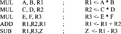
This sequence implements the statement Z = A * B + C * D - E * F. The three-address format, in addition to the other formats is normally used by typical 32-bit microprocessors such as the Intel Pentium and the Motorola 68000.
If we drop the third address from the three-address format, we obtain the two-address format, whose general form is
<op-code> Addr1,Addr2
Some typical two-address instructions are
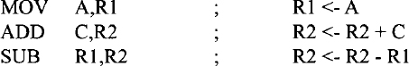
In this format, the addresses Addrl and Addr2 represent source and destination addresses, respectively. The following sequence of two-address instructions is equivalent to the program using three-address format presented earlier:

This format is predominant in typical general-purpose microprocessors such as the Pentium and 68000/68020. Typical 8-bit microprocessors such as the Intel 8085 and the Motorola 6809 are accumulator based. In these microprocessors, the accumulator register is assumed to be the destination for all arithmetic and logic operations. Also, this register always holds one of the source operands. Thus, we only need to specify one address in the instruction, and therefore, this idea reduces the instruction length. The one-address format is predominant in 8-bit microprocessors. Some typical one-address instructions are
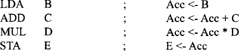
The following program illustrates how we can translate the C language statement, z = (a * b) + (c * d) - (e * f); into a sequence of one-address instructions:

In this program, t1 and t2 represent the addresses of memory locations used to store temporary results. Instructions that do not require any addresses are called zero-address instructions. All microprocessors include some zero-address instructions in the instruction set. Typical examples of zero-address instructions are CLC (clear carry) and NOP.
5.3.6 Instruction Set Architecture (ISA)
An instruction set architecture (ISA) defines the assembly instructions (instruction set) of a microprocessor. Each instruction specifies the operation to be performed and includes one or more operands. An assembly language program typically contains a number of assembly instructions. ISAs have been distinguished based on the number of operands that can be specified in each instruction. Typical examples include two- and three-operand instructions.
Earlier 8-bit microprocessors such as the Intel 8085 are accumulator-based machines. To add two numbers, these microprocessors used a dedicated register called the accumulator to hold one of the data to be added. A single-operand ADD instruction such as ADD B specifies the add operation to be performed between the contents of an 8-bit register B and the contents of the 8-bit accumulator. The 8-bit result is stored back in the accumulator. In these microprocessors, single-operand instructions are predominant.
Typical 32-bit microprocessors such as the Pentium assume that both operands to be added are stored in registers. For example, the Pentium instruction ADD BX,CX will add the 16-bit contents of register BX with the 16-bit contents of register CX. The 16-bit result will be stored in BX. Two-operand instructions are predominant in these microprocessors.
A particular microprocessor's hardware implementation of an ISA is normally called that microprocessor's microarchitecture. Since the 1990s, new microarchitectures have been implemented with existing ISAs. This is because the time and cost of developing assemblers/compilers and operating systems for a new ISA can be enormous. Microprocessors such as the Pentium have been designed basically with an existing ISA. Note that Intel's x86 hardware became more complex with each successive generation, whereas the ISA was mostly unchanged. Intel extended the original x86 ISA to include the floating-point instructions in the Pentium.
5.3.7 Typical Instruction Set
An instruction set of a specific microprocessor consists of all the instructions that it can execute. The capabilities of a microprocessor are determined to some extent by the types of instructions it is able to perform. Each microprocessor has a unique instruction set designed by its manufacturer to do a specific task. We discuss some of the instructions that are common to all microprocessors. We group together chunks of these instructions which have similar functions. These instructions typically include:
- Arithmetic and Logic Instructions. These operations perform actual data manipulations. The instructions typically include arithmetic/logic, increment/decrement, and rotate/shift operations. Typical arithmetic instructions include ADD, SUBTRACT, COMPARE, MULTIPLY, and DIVIDE. Note that the SUBTRACT instruction provides the result and also affects the status flags, whereas the COMPARE instruction performs subtraction without any result and affects the flags based on the result.
Typical microprocessors utilize common hardware to perform addition and subtraction operations for both unsigned and signed numbers. The instruction set for a microprocessor typically includes the same ADD and SUBTRACT instructions for both unsigned and signed numbers. The interpretations of unsigned and signed ADD and SUBTRACT operations are performed by the programmer. For example, consider adding two 8-bit numbers, A and B (A = FF16 and B = FF16) using the ADD instruction by a microprocessor as follows:

When the addition above is interpreted by the programmer as an unsigned operation, the result will be A + B = FF16 + FF16 = 25510+ 25510= 51010 which is FE16with a carry, as shown above. However, if the addition is interpreted as a signed operation, then A + B = FF16 + FF16 = (−110) + (−110) = −210 which is FE as shown above, and the final carry must be discarded by the programmer. Similarly, the unsigned and signed subtraction can be interpreted by the programmer.
Typical 16- and 32-bit microprocessors include both unsigned and signed multiplication and division instructions. Several unsigned multiplication algorithms are available. Multiplication of two unsigned numbers can be accomplished via repeated addition. For example, to multiply 410 by 310, the number 410 can be added twice to itself to obtain the result, 1210.
Division between unsigned numbers can be accomplished via repeated subtraction. For example, consider dividing 710 by 310 as follows:

Quotient = counter value = 2
Remainder = subtraction result = 1
Here, 1 is added to a counter whenever the subtraction result is greater than the divisor. The result is obtained as soon as the subtraction result is smaller than the divisor.
Signed multiplication can be performed using various algorithms. A simple algorithm follows. Assume that M (multiplicand) and Q (multiplier) are in two's-complement form. For the first case, perform unsigned multiplication of the magnitudes without the sign bits. The sign bit of the product is determined as Mn ![]() Qn, where Mn and Qn are the most significant bits (sign bits) of the multiplicand (M) and the multiplier (Q), respectively. To perform signed multiplication, proceed as follows:
Qn, where Mn and Qn are the most significant bits (sign bits) of the multiplicand (M) and the multiplier (Q), respectively. To perform signed multiplication, proceed as follows:
- If Mn = 1, compute the twos complement of M.
- If Qn = 1, compute the twos complement of Q.
- Multiply the n −1 bits of the multiplier and the multiplicand using unsigned multiplication.
- The sign of the result,
 .
. - If Sn = 1, compute the two's-complement of the result obtained in step 3.
Next, consider a numerical example. Assume that M and Q are two's-complement numbers. Suppose that M = 11002 and Q = 01112. Because Mn = 1, take the two's-complement of M = 01002; because Qn = 0, do not change Q. Multiply 01112 and 01002 using the unsigned multiplication method discussed before. The product is 000111002. The sign of the product ![]() . Hence, take the two's-complement of the product 000111002 to obtain 111001002, which is the final answer: −2810.
. Hence, take the two's-complement of the product 000111002 to obtain 111001002, which is the final answer: −2810.
Unsigned division can be performed using repeated subtraction. However, the general equation for division can be used for signed division. Note that the general equation for division is dividend = quotient * divisor + remainder. For example, consider dividend = −9, divisor = 2. Three possible solutions are shown below:
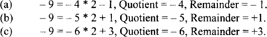
However, the correct answer is shown in (a), in which, the Quotient = −4 and the remainder = −1. Hence, for signed division, the sign of the remainder is the same as the sign of the dividend, unless the remainder is zero. Typical microprocessors such as the Pentium follow this convention.
Typical logic instructions perform traditional Boolean operations such as AND, OR, and EXclusive-OR. The AND instruction can be used to perform a masking operation. If the bit value in a particular bit position is desired in a word, the word can be logically ANDed with appropriate data to accomplish this. For example, the bit value at bit 2 of an 8-bit number 0100 1Y10 (where an unknown bit value of Y is to be determined) can be obtained as follows:

If the bit value Y at bit 2 is 1, the result is nonzero (flag Z = 0); otherwise, the result is zero (Flag Z = 1). The Z flag can be tested using typical conditional JUMP instructions such as JZ (Jump if Z=l) or JNZ (Jump if Z = 0) to determine whether Y is 0 or 1. This is called a masking operation. The AND instruction can also be used to determine whether a binary number is ODD or EVEN by checking the least significant bit (LSB) of the number (LSB = 0 for even and LSB = 1 for odd). The OR instruction can typically be used to insert a 1 in a particular bit position of a binary number without changing the values of the other bits. For example, a 1 can be inserted using the OR instruction at bit 3 of the 8-bit binary number 01110011 without changing the values of the other bits:

The Exclusive-OR instruction can be used to find the one's-complement of a binary number by XORing the number with all 1's as follows:

Next, the concept of logic and arithmetic shift and rotate operations is reviewed. In a logical shift operation, a bit that is shifted out will be lost, and the vacant position will be filled with a 0. For example, if we have the number (11)10, after a logical right shift operation, the register contents shown in Figure 5.2 will occur. Typical examples of logic/arithmetic and shift/rotate operations are given in Table 5.2.

FIGURE 5.2 Logical right shift operation.
TABLE 5.2 Typical Logic/Arithmetic and Shift/ Rotate Operations
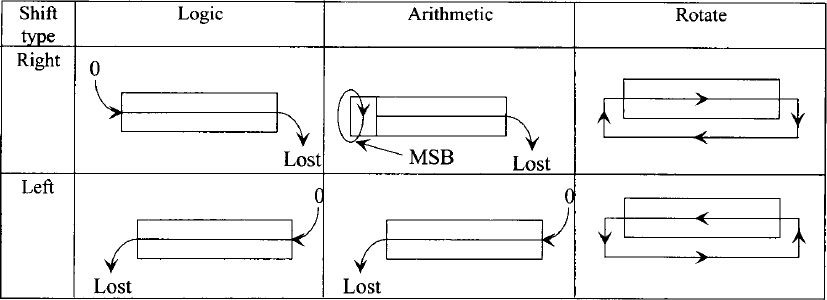
It must be emphasized that a logical left or right shift of an unsigned number by n positions implies multiplication or division of the number by 2n, respectively, provided that a 1 is not shifted out during the operation.
In the case of true arithmetic left or right shift operations, the sign bit of the number to be shifted must be retained. However, in computers, this is true for right shift and not for left shift operation. For example, if a register is shifted right arithmetically, the
most significant bit (MSB) of the register is preserved, thus ensuring that the sign of the number will remain unchanged. This is illustrated in Figure 5.3.
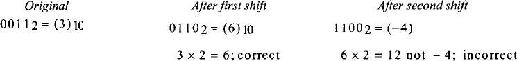
There is no difference between arithmetic and logical left shift operations. If the most significant bit changes from 0 to 1, or vice versa, in an arithmetic left shift, the result is incorrect and the microprocessor sets the overflow flag to 1. For example, if the original value of the register is (3)10, the results of two successive arithmetic left shift operations are interpreted as follows:

FIGURE 5.3 True arithmetic right shift operation.
- Instructions for controlling microprocessor operations. These instructions typically include those that set the reset specific flags and halt or stop the microprocessor.
- Data movement instructions. These instructions move data from a register to memory, and vice versa, between registers, and between a register and an I/O device.
- Instructions using memory addresses. An instruction in this category typically contains a memory address, which is used to read a data word from memory into a microprocessor register or for writing data from a register into a memory location. Many instructions under data processing and movement fall in this category.
- Conditional and unconditional JUMP. These instructions typically include one of the following:
1. An unconditional JUMP, which always transfers the memory address specified in the instruction into the program counter.
2. A conditional JUMP, which transfers the address portion of the instruction into the program counter based on the conditions set by one of the status flags in the flag register.
5.3.8 Typical Addressing Modes
One of the tasks performed by a microprocessor during execution of an instruction is the determination of the operand and destination addresses. The manner in which a microprocessor accomplishes this task is called the “addressing mode.” Now, let us present the typical microprocessor addressing modes, relating them to the instruction sets of Motorola 68000.
An instruction is said to have “implied or inherent addressing mode” if it does not have any operand. For example, consider the following instruction: RTS, which means “return from a subroutine to the main program.” The RTS instruction is a no-operand instruction. The program counter is implied in the instruction because although the program counter is not included in the RTS instruction, the return address is loaded in the program counter after its execution.
Whenever an instruction/operand contains data, it is called an “immediate mode” instruction. For example, consider the following 68000 instruction:
![]()
In this instruction the # indicates to the assembler that it is an immediate mode instruction. This instruction adds 15 to the contents of register D0 and then stores the result in D0. An instruction is said to have a register mode if it contains a register as opposed to a memory address. This means that the operand values are held in the microprocessor registers. For example, consider the following 68000 instruction:
![]()
This ADD instruction is a two-operand instruction. Both operands (source and destination) have a register mode. The instruction adds the 16-bit contents of D0 to the 16-bit contents of D1 and stores the 16-bit result in D0.
An instruction is said to have an absolute or direct addressing mode if it contains a memory address in the operand field. For example, consider the 68000 instruction
![]()
This instruction adds the 16-bit contents of memory address 3000 to the 16-bit contents of D2 and stores the 16-bit result in D2. The source operand to this ADD instruction contains 3000 and is in the absolute or direct addressing mode.
When an instruction specifies a microprocessor register to hold the address, the resulting addressing mode is known as the register indirect mode. For example, consider the 68000 instruction
CLR (A0)
This instruction clears the 16-bit contents of a memory location whose address is in register A0 to zero. The instruction is in register indirect mode.
Conditional branch instructions are used to change the order of execution of a program based on the conditions set by the status flags. Some microprocessors use conditional branching using the absolute mode. The op-code verifies a condition set by a particular status flag. If the condition is satisfied, the program counter is changed to the value of the operand address (defined in the instruction). If the condition is not satisfied, the program counter is incremented, and the program is executed in its normal order.
Typical 16-bit microprocessors use conditional branch instructions. Some conditional branch instructions are 16 bits wide. The first byte is the op-code for checking a particular flag. The second byte is an 8-bit offset, which is added to the contents of the program counter if the condition is satisfied to determine the effective address. This offset is considered as a signed binary number with the most significant bit as the sign bit. It means that the offset can vary from −12810 to +12710 (0 being positive). This is called the relative mode.
Consider the following 68000 example, which uses the branch not equal (BNE) instruction:
BNE 8
Suppose that the program counter contains 2000 (address of the next instruction to be executed) while executing this BNE instruction. Now, if Z = 0, the microprocessor will load 2000 + 8 = 2008 into the program counter and program execution resumes at address 2008. On the other hand, if Z = 1, the microprocessor continues with the next instruction.
In the last example the program jumped forward, requiring a positive offset. An example for branching with negative offset is BNE −14

Therefore, to branch backward to 1FF616, the assembler uses an offset of F2 following the op-code for BNE.
An advantage of the relative mode is that the destination address is specified relative to the address of the instruction after the instruction. Since these conditional Jump instructions do not contain an absolute address, the program can be placed anywhere in memory, which can still be executed properly by the microprocessor. A program that can be placed anywhere in memory and can still run correctly is called a relocatable program. It is a good practice to write relocatable programs.
5.3.9 Subroutine Calls in Assembly Language
It is sometimes desirable to execute a common task many times in a program. Consider the case when the sum of squares of numbers is required several times in a program. One could write a sequence of instructions in the main program for carrying out the sum of squares every time it is required. This is all right for short programs. For long programs, however, it is convenient for the programmer to write a small program known as a subroutine for performing the sum of squares, and call this program each time it is needed in the main program. Therefore, a subroutine can be defined as a program carrying out a particular function that can be called by another program, known as the main program. The subroutine only needs to be placed once in memory starting at a particular memory location. Each time the main program requires this subroutine, it can branch to it, typically by using a jump to subroutine (JSR) instruction along with its starting address. The subroutine is then executed. At the end of the subroutine, a RETURN instruction takes control back to the main program.
The 68000 includes two subroutine call instructions. Typical examples include JSR 4000 and BSR 24. JSR 4000 is an instruction using the absolute mode. In response to the execution of JSR, the 68000 saves (pushes) the current program counter contents (address of the next instruction to be executed) onto the stack. The program counter is then loaded, with 4000 included in the JSR instruction. The starting address of the subroutine is 4000. The RTS (return from subroutine) at the end of the subroutine reads (pops) the return address saved into the stack before jumping to the subroutine into the program counter. The program execution thus resumes in the main program. BSR 24 is an instruction using relative mode. This instruction works in the same way as the JSR 4000 except that displacement 24 is added to the current program counter contents to jump to the subroutine.
The stack must always be balanced. This means that a PUSH instruction in a subroutine must be followed by a POP instruction before the RETURN from subroutine instruction so that the stack pointer points to the right return address saved onto the stack. This will ensure returning to the desired location in the main program after execution of the subroutine. If multiple registers are PUSHed in a subroutine, one must POP them in the reverse order before the subroutine RETURN instruction.
5.4 High-Level Language
As mentioned earlier, a programmer's efficiency increases significantly with assembly language compared to machine language. However, the programmer needs to be well acquainted with the microprocessor's architecture and its instruction set. Further, the programmer has to provide an op-code for each operation that the microprocessor has to carry out in order to execute a program. As an example, for adding two numbers, the programmer would instruct the microprocessor to load the first number into a register, add the second number to the register, and then store the result in memory. However, the programmer might find it tedious to write all the steps required for a large program. Also, to become a reasonably good assembly language programmer, one needs to have a lot of experience.
High-level language programs composed of English-language-type statements rectify all these deficiencies of machine and assembly language programming. The programmer does not need to be familiar with the internal microprocessor structure or its instruction set. Also, each statement in a high-level language corresponds to a number of assembly or machine language instructions. For example, consider the statement f = a + b; written in a high-level language called C. This single statement adds the contents of a with b and stores the result in f. This is equivalent to a number of steps in machine or assembly language, as mentioned before. It should be pointed out that the letters a, b, and f do not refer to particular registers within the microprocessor. Rather, they are memory locations.
A number of high-level languages such as C and C++ are widely used at present. Typical microprocessors such as the Intel Pentium and the Motorola 68000/68020 can be programmed using these high-level languages. A high-level language is a problem-oriented language. The programmer does not have to know the details of the architecture of the microprocessor and its instruction set. Basically, the programmer follows the rules of the particular language being used to solve the problem at hand. A second advantage is that a program written in a particular high-level language can be executed by two different microcomputers, provided that they both understand that language. For example, a program written in C for a Pentium–based microcomputer will run on a 68020-based microcomputer because both microprocessors have a compiler to translate the C language into their particular machine language; minor modifications are required for I/O programs.
As mentioned before, like the assembly language program, a high-level language program requires a special program for converting the high-level statements into object codes. This program can be either an interpreter or a compiler. They are usually very large programs compared to assemblers. An interpreter reads each high-level statement such as F = A + B, and directs the microprocessor to perform the operations required to execute the statement. The interpreter converts each statement into machine language codes but does not convert the entire program into machine language codes prior to execution. Hence, it does not generate an object program. Therefore, an interpreter is a program that executes a set of machine language instructions in response to each high-level statement in order to carry out the function. A compiler converts each statement into a set of machine language instructions and also produces an object program that is stored in memory. This program must then be executed by the microprocessor to perform the required task in the high-level program.
In summary, an interpreter executes each statement as it proceeds, without generating an object code, whereas a compiler converts a high-level program into an object program that is stored in memory. This program is then executed.
5.5 Choosing a programming language
Compilers normally provide inefficient machine codes because of the general guidelines that must be followed for designing them. C/C++ is a high-level language that includes I/O instructions. However, the compiled codes generate many more lines of machine code than does an equivalent assembly language program. Therefore, the assembled program will take up less memory space and will execute much faster than the compiled C/C++. Although C/C++ language includes I/O instructions, applications involving I/O are normally written in assembly language. One of the main uses of assembly language is in writing programs for real-time applications. Real time indicates that the task required by the application must be completed before any other input to the program can occur that would change its operation. Typical programs involving non-real-time applications and extensive mathematical computations may be written in C/C++.

5.6 Flowcharts
Before writing an assembly language program for a specific operation, it is convenient to represent the program in a schematic form called a flowchart. A brief listing of the basic shapes used in a flowchart and their functions is given in Table 5.3.
Questions and Problems
| 5.1 | What is the basic difference between assembly and high-level languages? Why would you choose one over the other? |
| 5.2 | Assume that two microprocessors, the Pentium and the 68020, have C compilers. Will a program written in C language run on both microprocessors? |
| 5.3 | Will a program written in Pentium assembly language run on a 68020? |
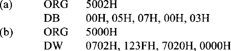
| 5.4 | Determine the contents of address 500416 after assembling the following:
|
| 5.5 | What is the difference between:
|
| 5.6 | Write a program equivalent to the C language assignment statement
z = a + (b * c) + (d * e) - (f / g) - (h * i); Use only:
|
| 5.7 | Assume that a microprocessor has only two registers, R1 and R2, and that only the following instruction is available:
Using this XOR instruction, find an instruction sequence to exchange the contents of registers Rl and R2. |
| 5.8 | Assume 2 two's-complement signed numbers, M = 111111112 and Q = 111111002. Perform signed multiplication using the algorithm described in section 5.3.7. |
| 5.9 | Using the convention described in section 5.3.7, find the quotient and remainder of (−25)/3. |
| 5.10 | Find the logic operation and 8-bit data for clearing bits 2 and 4 of an 8-bit number, 7E16 to 0's without changing the other bits. |
| 5.11 | Find the logic operation and 8-bit data for setting bits 0 and 7 of an 8-bit number, 3A16 to 1's without changing the other bits. |
| 5.12 | Find the overflow bit after performing an arithmetic shift on B616 three times to the left. |
| 5.13 | Describe the meaning of each of the following addressing modes.
|
| 5.14 | What are the advantages of subroutines? |
| 5.15 | Explain the use of a stack in implementing subroutine calls. |