
11
ASSEMBLY LANGUAGE PROGRAMMING WITH THE PENTIUM: PART 2
In this chapter we provide the second part of the Pentium's instruction set. Topics include logic, bit manipulation, set on conditions, shift and rotate, unconditional transfers including subroutine calls/returns, conditional branch, iteration control, interrupt, and processor control instructions. Several assembly language programming examples using most of these instructions are provided. Finally, delay routines using Pentium's instructions are covered.
11.1 Logic, Bit Manipulation, Set on condition, Shift, and Rotate Instructions
The logic, bit manipulation, set on condition, shift, and rotate instructions of the Pentium are listed in Table 11.1. Let us explain some of the instructions in the table.
- The NOT mem/reg instruction finds the one's complement of the operand. That is, this instruction converts all 0's to l's, and vice versa. No flags are affected. The operand mem/reg can be 8-, 16-, or 32-bit. Typical examples include NOT BL, NOT AX, NOT EDX, and NOT DWORD PTR [EBX]. As an example, consider NOT BL. If prior to execution of this instruction, the contents of BL = 2AH = 0010 10102, then after execution of NOT BL, the contents of BL = 1101 01012 = D5H.
TABLE 11.1 Pentium Logic, Bit Manipulation, Set on condition, Shift and Rotate Instructions

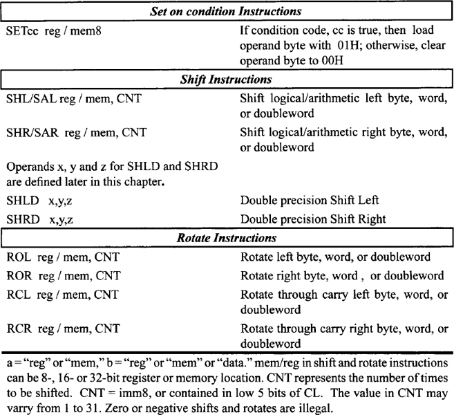
- AND a, b performs bit-by-bit logical AND operation between the two operands and stores the result in the destination operand. The destination operand ‘a’ can be memory or register while the source operand ‘b’ can be memory, register, or immediate data. The operand sizes can be 8-, 16-, or 32-bit. Typical examples include AND DL, AH, AND AX, BX, AND EAX, EDX, AND EDI, 2134A500H, and AND WORD PTR [SI],4. As an example, consider the AND BH,8FH instruction. If prior to execution of this instruction, (BH) = 72H, then after execution of AND BH,8FH, the following result is obtained:
ZF = 0 (result is nonzero), SF = 0 (most significant bit of the result is 0), and PF = 0 (result has odd parity). CF, AF, and OF are always cleared to 0 after a logic operation. The status flags are similarly affected after execution of other logic instructions, such as OR, XOR, NOT, and TEST.
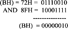
The AND instruction can be used to perform a masking operation. If the bit value in a particular bit position is desired in a word, the word can be logically ANDed with appropriate data to accomplish this. For example, the bit value at bit 2 of an 8-bit number 01001Y10 (where an unknown bit value of Y is to be determined) can be obtained as follows:
If the bit value Y at bit 2 is 1, the result is nonzero (flag Z = 0); otherwise, the result is zero (flag Z = 1). The Z flag can be tested using typical conditional JUMP instructions such as JZ (jump if Z = 1) or JNZ (jump if Z = 0) to determine whether Y is 0 or 1. This is called a masking operation. The AND instruction can also be used to determine whether a binary number is ODD or EVEN by checking the least significant bit (LSB) of the number (LSB = 0 for even and LSB = 1 for odd).
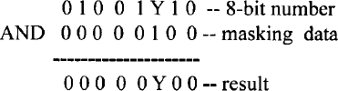
- OR a, b performs bit-by-bit logical OR operation between the two operands and stores the result in the destination operand. The destination operand ‘a’ can be memory or register, while the source operand ‘b’ can be memory, register, or immediate data. The operand sizes can be 8-, 16-, or 32-bit. All flags are affected. Typical examples include OR CL, AH, OR AX, DX, OR ESI, EDX, OR EAX, 2F34A500H, and OR WORD PTR [BX], 4. As an example, consider OR DL,AH. If prior to execution of this instruction, (DL) = A2H and (AH) = 5DH, then after exection of OR DL,AH, the content of DL is FFH. The flags are affected in the same manner as the AND instruction. The OR instruction can typically be used to insert a 1 in a particular bit position of a binary number without changing the values of the other bits. For example, a 1 can be inserted using the OR instruction at bit 3 of the 8-bit binary number 0 1 1 1 0 0 1 1 without changing the values of the other bits as follows:
- XOR a, b performs bit-by-bit Exclusive-OR operation between the two operands and stores the result in the destination operand. Destination operand ‘a’ can be memory or register while the source operand ‘b’ can be memory, register, or immediate data. The operand sizes can be 8-, 16-, or 32-bit. All flags are affected. Typical examples include XOR CL,BL, XOR SI,BX, XOR ECX,EDX, XOR EBX,24C4A500H or XOR BYTE PTR [DI],2AH.
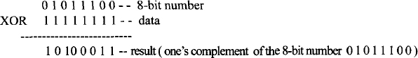
As an example, consider XOR CX,2. If prior to execution of this instruction,(CX)= 2342H, then after execution of XOR CX,2, the 16-bit contents of CX will be 2340H. All flags are affected in the same manner as the AND instruction. The Exclusive-OR instruction can be used to find the ones complement of a binary number by XORing the number with all 1's as follows:
- TEST a, b performs a bit-by-bit logical AND operation between the two operands but does not store the result in the destination operand; the flags are affected in the same manner as the AND instruction. The destination operand ‘a’ can be memory or register while the source operand ‘b’ can be memory, register, or immediate data. The operand sizes can be 8-, 16-, or 32-bit. Typical examples include TEST DL,AH, TEST CX,BX, TEST EBX,EDX, TEST EDI,2C34A500H, and TEST WORD PTR [DI],4. As an example, consider TEST CL,05H. This instruction logically ANDs (CL) with 000001012 but does not store the result in CL. All flags are affected.
- BSF d, s takes the form:
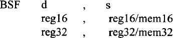
The source operand (s) can be 16- or 32-bit register or memory location. The destination operand (d) can be a 16- or 32-bit register. This instruction scans the bits of the source operand (s) starting with the least significant bit (bit 0) in order to find the first bit that equals 1. The bit number of the first 1 found is stored in d, and the ZF flag is cleared to 0. The ZF is set to 1 if the whole 16- or 32-bit number is 0, and in that case, the contents of any register or memory location do not change. The other flags OF, SF, AF, PF, and CF are undefined. For example, consider BSF EBX,EDX. If (EDX) = 01241240H, then after execution of the BSF EBX,EDX instruction, (EBX) = 00000006H and ZF = 0 since (EDX) is nonzero. Bit 6 in EDX (contained in the lower byte of EDX) is the first 1 found when (EDX) is scanned from the right.
- Consider BSR d, s. Operands d and s for BSR are the same as BSF. The source operand (s) can be 16- or 32-bit register or memory location. The destination operand (d) can be a 16- or 32-bit register. This instruction scans the bits of the source operand, (s) starting with the most significant bit (bit 31 or bit 15) to find the first bit that equals 1. The bit number of the first one found is stored in ‘d’, and the ZF is set to 1 if the whole 16- or 32-bit number is 0; otherwise, the ZF flag is cleared to 0. The other flags OF, SF, AF, PF, and CF are undefined. For example, consider BSR AX,CX. If (CX) = 25F1H, then after execution of the BSF AX, CX instruction, (AX) = 1310 = 000DH since bit 13 is the first bit set to 1 when scanned from left. ZF = 0 since (CX) is nonzero.
- BT (bit test) takes the form:
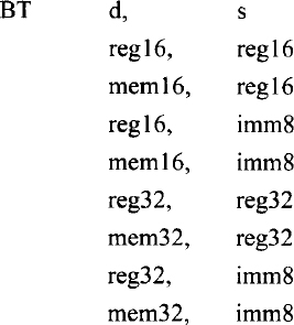
BT assigns the bit value of the destination operand d, specified by the source operand s (bit offset) to the carry flag. Only CF is affected. CF contains the value of the bit selected. If operand ‘s’ is immediate data, only 8 bits are allowed in the instruction. This operand is taken modulo 32; hence, the range of immediate bit offset is from 0 to 31. This permits any bit within a register to be selected. If d is a register, the bit value assigned to CF is defined by the value of the bit number defined by s taken modulo the register size. Note that BSF and BSR instructions do not provide modulo operands. For memory bit strings, immediate field gives only the bit offset within a word or doubleword. When accessing a bit in memory, the Pentium may access four bytes starting from the memory address given by: Effective Address + (4* (Bit offset DIV 32)) for a 32-bit operand size or two bytes starting from the memory address given by: Effective Address + (2 * (Bit offset DIV 16)) for a 16-bit operand size.
Next, as an example, consider BT EAX,2. If (EAX) = FFFF0080H, then after BT EAX,2, the CF will be cleared to 0 since bit 2 of EAX is 0. Next, consider BT ECX,33. If(ECX) = 1234081FH, then after BT ECX,33, because the immediate data (s) is 3310, bit 1 (the remainder of 33/32 = bit 1 of ECX ) is reflected in CF, and therefore CF = 1.
- BTC (bit test and complement) takes the form

where d and s have the same definitions as for the BT instruction. The bit of d defined by s is reflected in CF. After CF is assigned, the same bit of d defined by s is one's-complemented. The Pentium determines the bit number from s (whether s is immediate data or register) and d (whether d is register or memory) in the same way as for the BT instruction.
- BTR (bit test and reset) takes the form
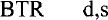
where d and s have the same definitions as for the BT instruction. The bit of d defined by s is reflected in CF. After CF is assigned, the same bit of d defined by s is reset to 0. Everything else applicable to the BT instruction also applies to BTR.
- BTS (bit test and set) takes the form
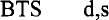
BTS is the same as BTR except that the bit in d specified by s is set to 1 after the bit value of d defined by s is reflected in CF. Everything else applicable to the BT instruction also applies to BTS.
- Consider SETcc reg8 / mem8. This instruction checks the specified condition and sets a byte in mem/reg to 01H if true or reset the byte in mem/reg to 00H if false. Appendix F lists the various conditions used with the SETcc instruction. Typical examples of this include SETC mem/reg (set byte in operand if the carry flag is 1), SETZ mem/reg (set byte in operand if the zero flag is 1), and SETO mem/reg (set byte in operand if the overflow flag is 1). Note that mem/reg can be a byte located in memory or in the lowest byte of the general register. No flags are affected. As an example, consider SETZ BL. If (BL) = 52H and ZF = 1, then, after this instruction is executed, (BL) = 01H. On the other hand, if ZF = 0, then, after execution of this instruction, (BL) = 00H. The other SETcc instructions can be explained similarly.
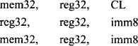
- The basic concepts associated with shift and rotate operations are covered in Chapter 5. In this section, some of the Pentium shift and rotate instructions are illustrated by means of numerical examples. Consider SHR mem/reg,CNT which has the following operands:
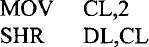
SHR mem/reg,CNT instruction performs logical right shift on the contents of the destination operand (mem/reg) specified by the shift count in the source operand. The source operand can be 8-bit immediate data or contained in register CL. The shift count may vary from 1 to 31. If a shift count greater than 31 is attempted, only the bottom five bits of the shift count are used. When CL is the shift count, its contents do not change after execution of the shift instruction. Figure 11.1 shows the operation of SHR mem/reg,CNT. Note that the least significant bit shifted out goes to CF (the carry flag) and 0 is shifted into the most significant bit. Finally, the content of register or memory is shifted to right based on the shift count. As an example, consider the following instruction sequence:
The above instruction sequence is equivalent to SHR DL, 2.
If prior to execution of the instruction sequence above, the contents of DL are 97H and CF = 0, then after execution of this instruction sequence, (DL) = 25H and CF = 1.
SHR can be used to divide an unsigned number by 2n by shifting the number n times to the right as long as a 1 is not shifted out of the least significant bit. Since execution time of the unsigned division instruction (DIV) is longer, unsigned division by SHR may be more efficient.
- SHL mem/reg,CNT works in the same way as the SHR mem/reg,CNT except that the contents of mem/reg are logically shifted to the left. Operation of the instruction SHL mem/reg, CNT is shown in Figure 11.1. This instruction has the same operands as SHR mem/reg, CNT. As an example, consider SHL BL, 1. This instruction logically shifts the contents of BL one bit to the left. Suppose that prior to execution of this instruction, if (BL) = A1H and CF = 0, then after SHL Bl, l, the contents of BL are 42H and CF= 1.
SHL can be used to multiply an unsigned number by 2n by shifting the number, n times to the left as long as a 1 is not shifted out of the most significant bit. Since the execution time of the unsigned multiplication instruction (MUL) is longer, unsigned multiplication by SHL may be more efficient.
- Figure 11.2 shows the operations of SAR mem/reg,CNT or SAL mem/reg,CNT. These instructions have the same operands as the SHR mem/reg, CNT. SAR can be used to divide a signed number by 2n by shifting the number n times to right as long as a 1 is not shifted out of the least significant bit. Since execution time of the signed division instruction (IDIV) is longer, signed division by SAR may be more efficient.
SAL and SHL perform the same operation except that SAL sets OF to 1 if the sign bit of the number being shifted changes during or after shifting. SAL can be used to multiply a signed number by 2n by shifting the number n times to left; the result is correct if OF = 0 while the result is incorrect if OF = 1. Since the execution time of the signed multiplication instruction (IMUL) is longer, multiplication by SAL may be more efficient.
- Multiplication and division by shifting a binary number by 2n is desirable in applications such as communication systems. Note that in communication systems, the number of samples is normally chosen by the designer as powers of 2. Hence, to multiply or divide other parameters by the number of samples, multiplication or division using shift instructions rather than Pentium's multiplication or division instructions (MUL, IMUL, DIV, IDIV) are desirable. This may be very useful in real-time systems.
- ROL mem/reg,CNT rotates (mem/reg) left by the specified number of bits (Figure 11.3). The operands are the same as the SHR mem/reg,CNT. The number of bits to be rotated is either 8-bit immediate data or contained in CL. For example, if CF = 0, (BX) = 0010H, and (CL) = 03H then, after ROL BX, CL, register BX will contain 0080H and CF = 0. On the other hand, ROL BL, 5 rotates the 8-bit contents of BL five times to the left. ROR mem/reg, CNT is similar to ROL except that the rotation is to the right (Figure 11.3).
- Figure 11.4 shows the operations of the instructions, RCL mem/reg,CNT and RCR mem/reg, CNT.
- Consider SHLD x, y, z and SHRD x, y, z instructions. The operands for these instructions are as follows:
FIGURE 11.1 SHR and SHL instructions.
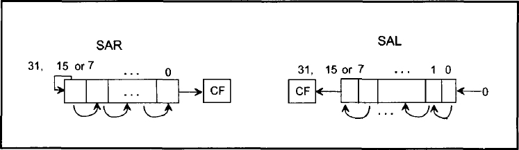
FIGURE 11.2 SAR and SAL instructions.

FIGURE 11.3 ROL and ROR instructions.
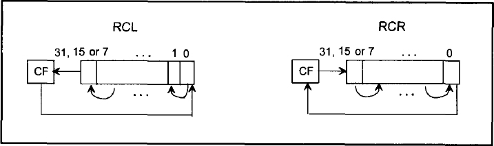
FIGURE 11.4 RCL and RCR instructions.

For both SHLD and SHRD, the shift count is defined by an immediate byte or the contents of CL. These operands are taken modulo 32 to provide a number between 0 and 31 by which to shift. Note that modulo 32 means that a shift count of 34 will shift the data twice (34/32 = remainder of 2).
SHLD shifts the contents of d:s by the specified shift count, with the result stored back into d; d is shifted to the left by the shift count with the low-order bits of d filled from the high-order bits of s. The bits in s are not altered after shifting. The carry flag becomes the value of the bit shifted out of the most significant bit of d. If the shift count is zero, this instruction works as a NOP. For the specified shift count, the SF, ZF, and PF flags are set according to the result in d. CF is set to the value of the last bit shifted out. OF and AF are undefined.
SHRD shifts the contents of d:s by the specified shift count to the right with the result stored back into d. The bits in d are shifted right by the shift count, with the high-order bits filled from the low-order bits of s. The bits in s are not altered after shifting. If the shift count is zero, this instruction operates as a NOP. For the specified shift count, the SF, ZF, and PF flags are set according to the value of the result. CF is set to the value of the last bit shifted out. OF and AF are undefined.
As an example, consider SHLD BX, DX, 2. If (BX) = 183FH and (DX) = 01F1H, then after execution of this SHLD instruction, (BX) = 60FCH, (DX) = 01F1H (unchanged), CF = 0, SF = 0, ZF = 0, and PF = 1. Similarly, the SHRD instruction can be illustrated.
EXAMPLE 11.1 It is desired to multiply a 32-bit unsigned number in EBX by 4 to provide a 32-bit product and then perform the following operations on the contents of EBX:
- Set bits 0 and 3 to 1 without changing other bits in EBX.
- Clear bit 30 to zero without changing other bits in EBX.
- Ones-complement bit 5 without changing other bits in EBX.
Assume data is already stored in EBX.
(a) Write a Pentium assembly language program to accomplish the above using only logic and shift instructions. Do not use any multiplication or any other instructions.
(b) Write a Pentium assembly language program to accomplish the above using only bit manipulation and shift instructions. Do not use multiplication, logic, or any other instructions.
Solution


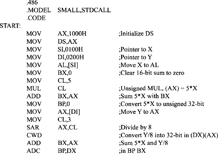
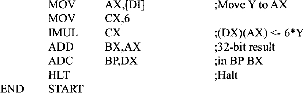
EXAMPLE 11.2 Write a Pentium assembly language program that will perform: 5 × X + 6 × Y + (Y/8) → (BP)(BX) where X is an unsigned 8-bit number stored at offset 0100H and Y is a 16-bit signed number stored as two bytes at offsets 0200H and 0201H respectively. Neglect the remainder of Y/8. Store the result in registers BX and BP. BX holds the low 16 bits of the 32-bit result and BP holds the high 16 bits of the 32-bit result. Initialize DS to 1000H.
Solution
11.2 String Instructions
Table 11.2 lists the Pentium string instructions. Note that string means that an array of data bytes, 16-bit words, or 32-bit doublewords is stored in consecutive memory locations. String instructions are available to MOVE, COMPARE, or SCAN for a value as well as to move string elements to and from AL, AX, or EAX. The instructions in Table 11.2, contain “repeat” prefixes that cause these instructions to be repeated in hardware, allowing long strings to be processed much faster than if done in a software loop.
Let us explain some of the instructions in Table 11.2.
- MOVSB, MOVSW, or MOVSD moves 8-, 16-, or 32-bit data from the memory location addressed by SI in DS to the memory location addressed by DI in ES. SI and DI are incremented automatically by 1 for byte, 2 for word, and 4 for doubleword if DF = 0; on the other hand, if DF = 1, then registers SI and DI are automatically decremented by 1 for byte, 2 for word, and 4 for doubleword. The instruction CLD can be used to clear the DF flag to 0 while the STD sets the DF flag to one. Automatic incrementing or decrementing of SI and DI will enable the programmer to move data between two strings from low to high addresses or from high to low addresses in memory. As mentioned in Chapter 10, the default segment register for source is DS, and it may be overridden; the segment register used for the destination must be ES, and cannot be overridden. An example is ES:MOVSW. In this case, both source and destination strings will use ES as the segment register.
Note that for 16-bit offset, SI and DI contain offsets for both source and destination strings while for 32-bit offset, ESI and EDI contain offsets for both source and destination strings. Also, for 32-bit offset in real mode, the contents of ESI and EDI vary from 00000000H to 0000FFFFH; this means that SI and DI contain offsets for doubleword string instructions such as MOVSD in real mode since low 16 bits of ESI and EDI are the same as SI and DI.
TABLE 11.2 Pentium String Instructions
REP Repeat MOVS or STOS until CX = 0 REPE / REPZ. Repeat CMPS or SCAS until ZF = 1 or CX = 0 REPNE / REPNZ Repeat CMPS or SCAS until ZF = 0 or CX = 0 MOVSB / MOVSW / MOVSD Move byte or word or doubleword string SCASB /SCASW / SCASD Scan byte or word or doubleword string LODSB /LODSW / LODSD Load from memory into AL or AX or EAX STOSB /STOSW/ STOSD Store AL or AX or EAX into memory As an example of MOVS instruction, consider MOVSW. If (DF) = 0, (DS)= 1000H, (ES) = 3000H, (SI) = 0002H, (DI) = 5000H. Assume that the contents of offset pointed to by SI =0002H in DS = 1000H are 1234H. That is, (physical address 10002H) = 1234H. This is depicted along with other data (chosen arbitrarily) in the Figure 11.5(a).
Now, after execution of the MOVSW instruction along with the above data, the contents of offset pointed to by DI = 5000H in ES = 3000H are 1234H. That is (physical address 35000H) = 1234H. Also, The contents of SI and DI are incremented (since DF =0) by 2 for word. Hence, (SI) = 0004H, and (DI) = 5002H. This is depicted in Figure 11.5(b).
Assuming (10002H) = 1234H, the following Pentium instruction sequence will accomplish the above:

Note that DS (source segment) in MOVS instruction can be overridden while the destination segment, ES is fixed, cannot be overridden. For example, the instruction ES: MOVSW will override the source segment, DS by ES while the destination segment remains at ES so that data will be moved in the same extra segment, ES.
- REP repeats the string instruction (such as MOVS) follows until the CX register is decremented to 0. As mentioned before, REP is implemented in hardware for faster operation. Next, consider moving (offset 1000H) to (offset 5000H), (offset 1001H) to (offset 5001H), and so on. Note that (offset 1000H) indicates the contents of offset 1000H in DS (source string) while (offset 5000H) means the contents of offset 5000H in ES (destination string). Assume (DS) = 2000H and (ES) = 4000H. The following Pentium assembly language program using LOOP instruction for moving 50 bytes from source to destination (from low to high addresses) will accomplish this:
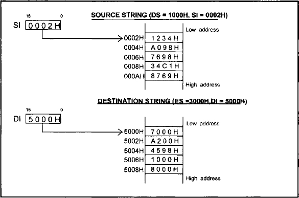
FIGURE 11.5(a) Source and destination strings prior to execution of MOVSW instruction

FIGURE 11.5(b) Source and destination strings after execution of MOVSW instruction

The above assembly language program can be replaced using REP prefix as follows:

Next, consider moving string data from high to low addresses. For example, suppose it is desired to move 8-bit data from (offset 2006H) to (offset 5008H), (offset 2005H) to (offset 5007H), and so on. The following Pentium assembly language program using LOOP instruction for moving 50 bytes from source to destination (from high to low addresses) will accomplish this:
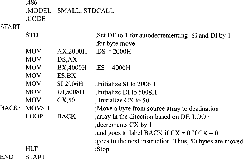
The above program can be replaced using REP prefix as follows:

- CMPSB or CMPSW or CMPSD in real mode subtracts without any result (affects flags accordingly) 8-, 16-, or 32-bit data in the source memory location addressed by SI in DS from the destination memory location addressed by DI in ES. SI and DI are incremented or decremented depending on the DF flag. For example, if (DF) = 0, (DS) = 1000H, (ES) = 3000H, (SI) = 0002H, (DI) = 0004H,(10002H) = 1234H, and (30004H) = 1234H then, after CMPSW, CF = 0, PF = 1,AF = 1, ZF = 1, SF = 0, OF = 0,(10002H) = 1234H, and (30004H) = 1234H, (SI) = 0004H, and (DI) = 0006H. Note that SI and DI are used as source and destination pointers for 16-bit offsets while ESI and EDI are used as source and destination pointers for 32-bit offsets.
- Consider SCASB / SCASW / SCASD. This compares the memory addressed by (DI) in ES with AL or AX or EAX. If (DI) = 0000H,(ES) = 2000H, (DF) = 0,(20000H) = 05H, and (AL) = 03H, then, after SCASB, register DI will contain 0001H because (DF) = 0 and all flags are affected based on the operation (AL) - (20000H). Hence, OF = 0, SF = 1, ZF = 0, AF = 0, PF = 0, and CF= 1.
- REPE/REPZ or REPNE/REPNZ prefix can be used with CMPS or SCAS to cause one of these instructions to continue executing until ZF = 0 (for the REPNE/REPNZ prefix) or CX = 0. The prefixes REPE and REPZ also provide similar purpose. If CMPS is prefixed with REPE or REPZ, the operation is interpreted as “compare while not end-of-string (CX ≠ 0) or strings are equal (ZF = 1).” If CMPS is preceded by REPNE or REPNZ, the operation is interpreted as “compare while not end-of-string (CX ≠ 0) or strings not equal (ZF = 0).” Thus, repeated CMPS instructions can be used to find matching or differing string elements.
- If SCAS is prefixed with REPE or REPZ, the operation is interpreted as “scan while not end-of-string (CX ≠ 0) or string-element = scan-value (ZF = 1)” This form may be used to scan for departure from a given value. If SCAS is prefixed with REPNE or REPNZ, the operation is interpreted as “scan while not end-of-string (CX ≠ 0) or string-element is not equal to scan-value (ZF = 0).” This form may be used to locate a value in a string.
- LODSB or LODSW or LODSD loads a byte into AL or a word into AX or a doubleword into EAX respectively from a string in memory addressed by SI in DS; SI is then automatically incremented or decremented by lfor byte, 2 for word, or 4 for doubleword based on DF. For example, prior to execution of LODSB, if (SI )=0020H, (DS) = 3000H, (30020H) = 05H, DF = 0, then after execution of LODSB, data 05H is loaded into AL; SI is then automatically incremented to 0021H since DF = 0.
- STOSB or STOSW or STOSD stores a byte in AL or a word in AX, or a doubleword in EAX respectively into a string memory addressed by DI in ES. DI is then automatically incremented or decremented by 1 for byte, 2 for word, or 4 for doubleword based on DF.


EXAMPLE 11.3 Write a Pentium assembly language program to compare a source string of 5010 words from low to high addresses pointed to by an offset 1000H in the data segment at 2000H with a destination string pointed to by an offset 3000H in the extra segment at 4000H. The program should be halted as soon as a match is found or the end of string is reached.
Solution

Note: REPNE CMPSW instruction in the above program will automatically decrement CX by 1, and checks whether ZF = 1. The CMPSW instruction is executed CX times if CX is not equal to 0 or strings are not equal (ZF = 0). This means that as soon as a match is found (ZF=1), the program will go to the next instruction (HLT). However, if no match is found (ZF = 0), the instruction, CMPSW will be executed CX times, and the program will then go the next instruction (HLT).
11.3 Unconditional Transfer Instructions
Unconditional transfer instructions transfer control to a location either in the current executing memory segment (intrasegment) or in a different code segment (intersegment). Table 11.3 lists the unconditional transfer instructions.
The jump instruction in Table 11.3 can be either intrasegment or near JMP (Jump within the current code segment; only IP changes) or intersegment or far JMP (Jump from one code segment to another code segment; both CS and IP contents are modified). The programmer can use NEAR and FAR directives to indicate intrasegment and intersegment Jump instructions.
Intrasegment Jump can have an operand with a short label (signed 8-bit displacement), near label (signed 16-bit displacement), reg 16 or mem 16. For example, the short label and near label operands use relative addressing mode. This means that the Jump is performed relative to the address of the JMP instruction. For jumps with short label, IP changes and CS is fixed. JMP disp8 adds the second object code byte (signed 8-bit displacement) to (IP + 2), and (CS) is unchanged. With an 8-bit signed displacement, jump with a short label operand is allowed in the range from −128 to +127 (0 being positive) from the address of the JMP instruction. Near label operand allows a JMP instruction to have a signed 16-bit displacement with a range -32K to +32K bytes from the address of the JMP instruction. An example of JMP short label or near label is JMP START.
The Pentium assembler automatically computes the value of the displacement START at assembly time. The programmer does not have to worry about it. Based upon the displacement size of START (in this case), the assembler determines whether the JMP is to be performed with short or near label. Short or Near Jumps are used in real mode. In protected mode, the Pentium can use a range of −2 Gigabytes to +2 Gigabytes.
The short jump and near jump are relocatable since they use relative addressing mode. This means that if the code segment moves to a new address in memory, the distance between the jump instruction, and the jump address stays the same. Thus, the code segment can easily be moved to anywhere in memory without modification. This is very convenient for the programmer.
In order to illustrate the concept of short jump, consider the following Pentium instruction sequence along with machine code provided by the MASM32 assembler:

Note that all instructions, addresses, and data are arbitrarily chosen. The first jump instruction (JMP DOWN) at offset 100DH (automatically generated by the assembler) has a machine code EB06H. This instruction unconditionally jumps to address DOWN. The machine code EB06H means that the opcode for JMP is EBH, and the relative displacement value is 06H (positive value meaning forward jump). This is a short jump since the range is between −128 and + 127. Note that the instruction pointer normally points to the next instruction. Hence, at offset 100DH, the IP will contain 100FH. The displacement 06H is added to 100FH to find the offset value where the program will unconditionally jump. The jump offset is calculated as follows:
TABLE 11.3 Pentium unconditional transfers
| JMP disp/reg/mem | Unconditional jump |
| CALL disp/reg/mem | Call subroutine |
| RET or RET disp 16 | Return from subroutine |
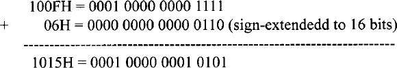
Hence, the instruction jumps to offset 1015H. This is verified in the above instruction sequence.
Next, consider the second jump instruction, JMP BACK. The machine code for this instruction at offset 1019H is EBECH where EBH is the opcode, and ECH is the signed displacement value. Since ECH is a negative number (−20), this is a backward jump. Note that the instruction pointer normally points to the next instruction. Hence, at offset 1019H, the IP will contain 101BH. The displacement 20 is subtracted from 101BH to find the offset value where the program will unconditionally jump. The jump offset is calculated as follows:
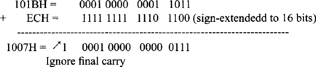
The jump offset is 1007H which is verified in the above instruction sequence. In the case of the short jump, the relative displacement is signed 8-bit contained in a byte with a range of −128 to +127 (0 being positive). When the jump offset is outside this range, but in the same segment, a near jump is used, and the jump offset is two bytes long.
JMP reg specifies the jump offset by the 16- or 32-bit contents of of a register. This is an indirect jump. In the real mode, the contents of the specified register are transferred directly into the IP. The range for this JMP is from −32K to +32K bytes from the address of the JMP. An example of JMP reg is JMP SI which copies the contents of SI into IP. SI contains the 16-bit displacement. In the real mode, JMP EBX can also be used to hold the jump offset in the low 16 bits of EBX. However, in the protected mode, since 32-bit offset is needed, EBX will contain the 32-bit offset, and the code segment can be 4 Gigabytes long.
An example of JMP mem 16 is JMP [DI] which uses the contents of DI as the address of the memory location containing the offset. This offset is placed into IP. The physical address is computed from this IP value and the current CS value.
Jump with FAR PTR directive uses a 32-bit immediate operand; the first 16 bits are loaded into IP while the next 16 bits are loaded into CS. An example of far jump is JMP FAR PTR BEGIN which unconditionally branches to a label BEGIN in a different code segment. Finally, JMP mem32 indirectly specifies the offset and the code segment values. IP and CS are loaded from the 32-bit contents of four consecutive memory locations; each memory location contains a byte. As an example, JMP FAR PTR [SI] loads IP and CS with the contents of four consecutive bytes pointed to by SI in DS.
The Pentium CALL instructions provide the mechanism to call a subroutine into operation while the RETinstruction placed at the end of the subroutine transfers control back to the main program. There are two types of Pentium CALL instruction. These are near, or intrasegment CALL (IP changes, CS is fixed), and far, or intersegment CALL (both IP and CS are changed).
Near and Far CALLs are defined by the various operands of the CALL instruction. For example, the three operands NEAR PROC, mem 16, and reg 16 define intrasegment CALLs to a subroutine. Upon execution of the intrasegment CALL with any of the three operands, the Pentium pushes the current contents of IP onto the stack; the SP is then decremented by 2. The saved IP value is the offset that contains the next instruction to be executed in the main program. The Pentium then places a new 16-bit value ( offset of the first instruction in the subroutine) into IP. The three types of operands for the intrasegment CALL will be discussed next.
These are near CALL, CALL mem 16, and CALL reg 16.
As an example of near CALL, consider the Pentium instruction sequence shown below:
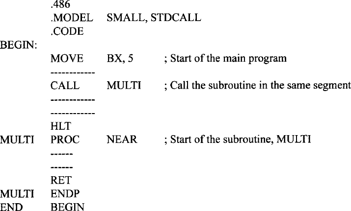
In the above, the main program, and the subroutine called MULTI are located in the same code segment. The assembler directive NEAR in the statement CALL NEAR PROC specifies the CALL instruction with relative addressing mode in the same code segment. This means that NEAR determines a 16-bit displacement, and the offset is computed relative to the address of the CALL instruction. With 16-bit displacement, the range of the CALL instruction is limited to −32766 to + 32765 (0 being positive). The Pentium uses 32-bit offset in protected mode with a range of −2Gigabytes to +2 Gigabytes. Since this subroutine is in the same code segment as the main program containing the CALL instruction, the contents of CS are not altered to access it. Note that use of the assembler directive NEAR in the statement MULTI PROC NEAR tells the Pentium assembler that the main program and the subroutine are located in the same code segment.
The instructions CALL mem 16 and CALL reg 16 specify a memory location or a 16-bit register such as BX to hold the offset to be loaded into IP. Thus, these two CALL instructions use indirect addressing mode. An example of CALL mem 16 is CALL [BX] which loads the 16-bit value stored in the memory location pointed to by BX into IP. The physical address of the offset is calculated from the current DS and the contents of BX. The first instruction of the subroutine is contained in the address computed from new IP value and current CS. Next, typical examples of CALL reg 16 are CALL BX and CALL BP; these instructions load the 16-bit contents of BX or BP into IP. The starting address (physical address) of the subroutine is computed from the new value of IP and the current CS contents. Note that intrasegment CALL instructions are used when the main program and the subroutine are located in the same code segment.
Intersegment CALL instructions are used when the main program and the subroutine are located in two different code segments. The two intersegment CALL instructions are CALL FAR PTR and CALL mem32. These instructions define a new offset for IP and a new value for CS. Upon execution of these two instructions, the Pentium pushes the current contents of IP and CS onto the stack, the new values of IP and CS are then loaded. For example consider CALL FAR PTR MULTI which loads the new value of IP from the next two bytes, and the new value of CS from the following two bytes. As an example, consider the following Pentium instruction sequence:
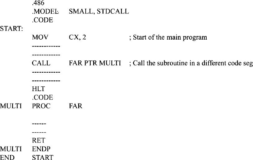
Since this subroutine is in a different code segment from the CALL instruction, the contents of CS must be altered to access it. Use of the assembler directive FAR in the statement MULTI PROC FAR tells the Pentium assembler that the main program and the subroutine are located in different code segments.
CALL FAR PTR [SI] stores the pointer for the subroutine as four bytes in data memory. The location of the first byte of the four-byte pointer is specified indirectly by one of the Pentium registers (SI in this case). In this example, in real mode, the 20-bit physical address of the first byte of the four-byte pointer is computed from DS and SI. Finally, CALL FAR PTR [BX] pushes CS and IP onto the stack and loads IP and CS with the contents of four consecutive bytes pointed to by BX.
RET instruction is usually placed at the end of a subroutine which pops IP (pushed onto the stack by the intrasegment CALL instruction) or both IP and CS (pushed onto the stack by the intersegment CALL instruction), and returns control to the main program. RET disp 16, on the other hand, adds 16-bit value ( disp 16) to SP after placing the return address into IP (for intrasegment CALL) or into IP and CS (for intersegment CALL). The main objective of inclusion of the 16-bit displacement operand with the RET instruction is to discard the parameters that were saved onto the stack before execution of the subroutine CALL instruction.
EXAMPLE 11.4 Write a subroutine in Pentium assembly language which can be called by a main program in the same code segment. The subroutine will multiply a signed 16-bit number in CX by a signed 8-bit number in AL. The main program will perform initializations (DS to 5000H, SS to 6000H, SP to 0020H, BX to 2000H, SI to 0000H, and DI to 0004H)), call this subroutine, store the result in two consecutive memory words, and stop. Assume SI and DI contain pointers to the signed 8-bit and 16-bit data respectively. Store 32-bit result in a memory location pointed to by BX.
Solution

EXAMPLE 11.5 Write a subroutine in Pentium assembly language in the same code segment as the main program to implement the C language assignment statement: p = p + q; where addresses p and q hold two 16-digit (64-bit) packed BCD numbers (N1 and N2). The main program will initialize addresses p and q to DS:2000H and DS:3000H respectively. Address DS:2007H will hold the highest byte of N1 with the lowest byte at address DS:2000H while address DS:3007H will hold the highest byte of N2 with the lowest byte at address DS:3000H. Also, write the main program which will perform all initializations including DS to 2000H, SS to 6000H, SP to 0020H, SI to 2000H, DI to 3000H, loop count to 8 and, then call the subroutine.
Solution

EXAMPLE 11.6 Write a subroutine in Pentium assembly language which can be called by a main program in a different code segment. The subroutine will compute ΣXi2 / N. Assume the Xi's are 16-bit signed integers, N = 100 and, ΣXi2 is 32-bit wide. The numbers are stored in consecutive locations. Assume SI points to the Xi'. The subroutine will initialize SI to 4000H, compute ΣXi2 / N, and store 32-bit result in DX:AX (16-bit remainder in DX and 16-bit quotient in AX). Also, write the main program which will initialize DS to 2000H, SS to 6000H, SP to 0040H, call the subroutine, and stop.
Solution

11.4 Conditional Branch Instructions
All Pentium conditional branch instructions use 8- bit displacement with a branch range of −128 to +127, (0 being positive) or 16-bit displacement with a branch range of −32766 to + 32765 (0 being positive. The structure of a typical conditional branch instruction is as follows:
![]()
There are two types of conditional branch instructions. In one type, the various relationships that exist between two numbers such as equal, above, below, less than, or greater than can be determined by the appropriate conditional branch instruction after a COMPARE instruction. These instructions can be used for both signed and unsigned numbers. When comparing signed numbers, terms such as “less than” and “greater than” are used. On the other hand, when comparing unsigned numbers, terms such as “below zero” or “above zero” are used.
Table 11.4 lists the Pentium signed and unsigned conditional branch instructions. Note that in Table 11.4, the instructions for checking which two numbers are “equal” or “not equal” are the same for both signed and unsigned numbers. This is because when two numbers are compared for equality, irrespective of whether they are signed or unsigned, they will provide a zero result (ZF = 1) if they are equal and a nonzero result (ZF = 0) if they are not equal. Therefore, the same instructions apply for both signed and unsigned numbers for “equal to” or “not equal to” conditions. The second type of conditional branch instructions is concerned with the setting of flags rather than the relationship between two numbers. Table 11.5 lists these instructions.
Now, in order to check whether the result of an arithmetic or logic operation is zero, nonzero, positive or negative, did or did not produce a carry, did or did not produce parity, or did or did not cause overflow, the following instructions should be used: JZ, JNZ, JS, JNS, JC, JNC, JP, JNP, JO, JNO. However, in order to compare two signed or unsigned numbers (a in address A or b in address B) for various conditions, we use CMP A, B, which will form a - b. and then one of the instructions in Table 11.6.
Now let us illustrate the concept of using the preceding signed or unsigned instructions by an example. Consider clearing a section of memory word starting at B up to and including A, where (A) = 3000H and (B) = 2000H in DS = 1000H, using the following instruction sequence:
TABLE 11.4 Pentium Signed and Unsigned Conditional Branch Instructions

TABLE 11.5 Pentium Conditional Branch Instructions Affecting Individual Flags
| JC disp8 | JUMP if carry, i.e., CF = 1 |
| JNC disp8 | JUMP if no carry, i.e., CF = 0 |
| JP disp8 | JUMP if parity, i.e., PF = 1 |
| JNP disp8 | JUMP if no parity. i.e., PF = 0 |
| JO disp8 | JUMP if overflow, i.e., OF = 1 |
| JNO disp8 | JUMP if no overflow, i.e., OF = 0 |
| JS disp8 | JUMP if sign, i.e., SF = 1 |
| JNS disp8 | JUMP if no sign, i.e., SF = 0 |
| JZ disp8 | JUMP if result zero, i.e., ZF = 1 |
| JNZ disp8 | JUMP if result not zero, i.e., ZF = 0 |
TABLE 11.6 Pentium Instructions to be used after CMP A, B; a and b are data.
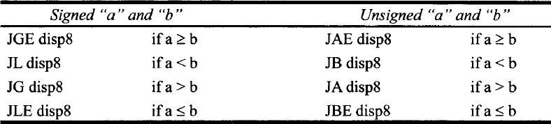
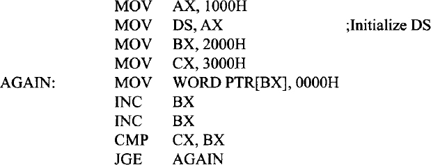
JGE treats CMP operands as twos complement numbers. The loop will terminate when BX = 3002H. Now, suppose that the contents of A and B are as follows: (A) = 8500H and (B) = 0500H.
In this case, after CMP CX,BX is first executed,
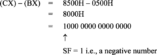
Because 800016 is a negative number, the loop terminates.
The correct approach is to use a branch instruction that treats operands as unsigned numbers (positive numbers) and uses the following instruction sequence:

JAE will work regardless of the values of A and B.
Also, note that addresses are always positive numbers (unsigned). Hence, unsigned conditional jump instruction must be used to obtain the correct answer. The examples above are included for illustrative purposes.
11.5 Iteration Control Instructions
Table 11.7 lists iteration control instructions. All these instructions have relative addressing modes. Also, these instructions use CX register as a 16-bit counter in real mode, and ECX register as a 32-bit counter in protected mode. In this section, iteration control instructions in real mode will be discussed. LOOP disp8 decrements the CX register by 1 without affecting the flags and then acts in the same way as the JMP dsp8 instruction except that if CX ≠ 0, then the JMP is performed: otherwise, the next instruction is executed. The LOOP uses signed 8-bit displacement.
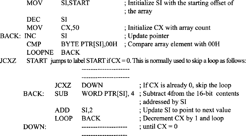
LOOPE (loop while equal)/LOOPZ (loop while zero) decrements CX by 1 without affecting the flags. The contents of CX are then checked for zero, and the zero flag (ZF), which results from execution of previous instruction, is checked for 1. If CX ≠ 0 and ZF =1, the loop continues. If either CX = 0 or ZF = 0, the next instruction after LOOPE or LOOPZ is executed. The following Pentium instruction sequence compares an array of 50 bytes with data byte 00H. As soon as a match is not found or the end of the array is reached, the loop exits. The LOOPE instruction can be used for this purpose. The following Pentium instruction sequence illustrates this.

LOOPNE (LOOP while not equal)/LOOPNZ (Loop while not zero) is similar to LOOPE/LOOPZ except that the loop continues if CX ≠ 0 and ZF = 0. On the other hand, If CX = 0 or ZF = 1, the next instruction is executed. The following Pentium instruction sequence compares an array of 50 bytes with data byte 00H for a match. As soon as a match is found or the end of the array is reached, the loop exits. LOOPNE instruction can be used for this purpose. CX = 0 and ZF = 0 upon execution of the CMP instruction 50 times in the following would imply that data byte 00H was not found in the array. The following Pentium instruction sequence illustrates this.
11.6 Interrupt Instructions
Table 11.8 shows the interrupt instructions. INT n is a software interrupt instruction. Execution of INT n causes the Pentium to push current CS, IP, and flags onto the stack, and loads CS and IP with new values based on interrupt type n; an interrupt service routine is written at this new address. IRET at the end of the service routine transfers control to the main program by popping old CS, IP, and flags from the stack.
The interrupt on overflow is a type 4 (n = 4) interrupt. This interrupt occurs if the overflow flag (OF) is set and the INTO instruction is executed. The overflow flag is affected, for example, after execution of a signed arithmetic (such as IMUL, signed multiplication) instruction. The user can execute an INTO instruction after the IMUL. If there is an overflow, an error service routine written by the user at the type 4 interrupt address vector is executed.
The IRET instruction is used in the real mode and is typically placed at the end of an interrupt service routine. The IRET pops IP, CS, and flags (lowest byte) from the stack.
TABLE 11.7 Pentium Iteration Control Instructions
| LOOP disp8 | Decrement CX by 1 without affecting the flags and branch to label if CX ≠ 0; otherwise, go to the next instruction. |
| LOOPE/LOOPZ disp8 | Decrement CX by 1 without affecting the flags and branch to label if CX ≠ 0 and ZF = 1; otherwise (CX=0 or ZF=0), go to the next instruction. |
| LOOPNE/LOOPNZ disp8 | Decrement CX by 1 without affecting the flags and branch to label if CX ≠ 0 and ZF = 0; otherwise (CX=0 or ZF=l), go to the next instruction. |
| JCXZ disp8 | JMP if register CX = 0; else go the next instruction. |
| JECXZ disp8 | Jump if ECX = 0; else go to the next instruction. |
Interrupt instructions are discussed in detail in Chapter 12.
11.7 Processor Control Instructions
Table 11.9 shows some of the processor control instructions. Let us explain some of the instructions in the table.
- The LOCK prefix allows the Pentium to ensure that another processor does not take control of the system bus while it is executing an instruction that uses the system bus. The LOCK prefix is placed in front of an instruction so that when the instruction is executed, the Pentium outputs a LOW on the LOCK # pin for the duration of the next instruction. This lock signal is connected to an external bus controller which prevents any other processor from taking over the system bus. Thus the LOCK prefix is used in multiprocessing. A typical example of a locked instruction is LOCK:MOV CL, [BX].
- ENTER and LEAVE are used with stack frames used to pass parameters to a subroutine through the stack. The ENTER imml6,imm8 instruction creates a stack frame. The data imm8 defines the nesting depth of the subroutine and can be from 0 to 31. The value 0 specifies the first subroutine only. Data imm8 defines the number of stack frame pointers copied into the new stack frame from the preceding frame. After the instruction is executed, the Pentium uses EBP as the current frame pointer and ESP as the current stack pointer. Data imml6 specifies the number of bytes of local variables for which stack space is to be allocated. If imm8 is zero, ENTER pushes the frame pointer EBP onto the stack; ENTER then subtracts the first operand, imml6, from the ESP and sets EBP to the current ESP.
TABLE 11.8 Pentium Interrupt Instructions
INT n Software interrupt instructions. ( n can be 0-25510) (INT 3210 − 25510 available to the user.) INTO Interrupt on overflow IRET Interrupt return (Real mode) TABLE 11.9 Pentium Processor Control Instructions
ENTER STC Set carry CF  1
1CLC Clear carry CF 0CMC Complement carry, CF 
STD Set direction flag CLD Clear direction flag STI Set interrupt enable flag CLI Clear interrupt enable flag NOP No operation HLT Halt LOCK Lock bus during next instruction ENTER Create stack frame LEAVE Reverses the action of ENTER; High level procedure exit BOUND Check array index against bounds For example, a procedure with 28 bytes of local variables would have an ENTER 28,0 instruction at its entry point and a LEAVE instruction before every RET. The 28 local bytes would be addressed as offset from EBP. Note that the LEAVE instruction sets ESP to EBP and then pops EBP. The Pentium uses BP (the low 16 bits of EBP) and SP (the low 16 bits of ESP) for 16-bit operands and uses EBP and ESP for 32-bit operands.
- The BOUND instruction ensures that a signed array index is within the limits specified by a block of memory containing an upper and a lower bound. The Pentium provides two forms of the BOUND instruction:
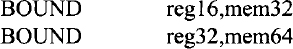
The first form is for 16-bit operands. The second form is for 32-bit operands and is included in the Pentium instruction set. For example, consider BOUND EDI,ADDR. Suppose that (ADDR) = 32-bit lower bound dl and (ADDR + 4) = 32-bit upper bound du. If, after execution of this instruction, (EDI) < dl or > du the Pentium traps to interrupt 5; otherwise, the array is accessed.
The BOUND instruction is usually placed following the computation of an index value to ensure that the limits of the index value are not violated. This permits a check to determine whether or not an address of an array being accessed is within the array boundaries when the register indirect with index mode is used to access an array element. For example, the following instruction sequence will allow accessing an array with base address in ESI, index value in EDI, and an array length of 50 bytes; assuming that the 32-bit contents of memory location, 2000010016 and 2000010416 are 0 and 49, respectively:

11.8 Pentium Delay routine
Typical Pentium software delay loops can be written using MOV and LOOP instructions. For example, the following instruction sequence can be used for a delay loop:
![]()
The initial loop counter value of “count” can be calculated using the cycles required to execute the following Pentium instructions (Appendix F):
![]()
Note that the Pentium LOOP instruction requires two different execution times. LOOP requires six cycles when the Pentium branches if the CX is not equal to zero after autodecrementing CX by 1. However, the Pentium goes to the next instruction and does not branch when CX = 0 after autodecrementing CX by 1, and this requires five cycles. This means that the DELAY loop will require six cycles for (count - 1) times, and the last iteration will take five cycles.
For a 100-MHz Pentium clock, each cycle is 10 ns. For 2 ms, total ![]()
![]() . The loop will require six cycles for (count - 1) times when CX ≠ 0, and five cycles will be required when no branch is taken (CX = 0). Thus, total cycles including the MOV = 1 + 6 × (count - 1) + 5 = 200,000. Hence, count ≅ 33,33310. Therefore, CX must be loaded with 33,33310.
. The loop will require six cycles for (count - 1) times when CX ≠ 0, and five cycles will be required when no branch is taken (CX = 0). Thus, total cycles including the MOV = 1 + 6 × (count - 1) + 5 = 200,000. Hence, count ≅ 33,33310. Therefore, CX must be loaded with 33,33310.
Now, in order to obtain delay of 2 seconds, the above DELAY loop of 2 ms can be used with an external counter. Counter value = (2 sec)/(2 msec) = 1000. The following instruction sequence will provide an approximate delay of 2 seconds:

Next, the delay time provided by the instruction sequence above can be calculated. From Appendix F, we obtain the number of cycles required to execute the following Pentium instructions:
As berore, assuming a l00-MHz Pentium clock, each cycle is 10ns. Ihe total time from the above instruction sequence for 2-second delay = execution time for MOV + 1000 * (2 msec delay) + 1000 * (execution time for DEC ) + 1000* (execution time for JNE) = 1 * 10 ns + 1000 * 2 msec + 1000 * 1 * 10ns + 1000 * 1 * 10ns ≅ 2 seconds discarding the execution times of MOV, DEC, and JNE.