
APPENDIX D
68000 EXECUTION TIMES
D.1 INTRODUCTION
This Appendix contains listings of the instruction execution times in terms of external clock (CLK) periods. In this data, it is assumed that both memory read and write cycle times are four clock periods. A longer memory cycle will cause the generation of wait states which must be added to the total instruction time.
The number of bus read and write cycles for each instruction is also included with the timing data. This data is enclosed in parenthesis following the number of clock periods and is shown as: (r/w) where r is the number of read cycles and w is the number of write cycles included in the clock period number. Recalling that either a read or write cycle requires four clock periods, a timing number given as 18(3/1) relates to 12 clock periods for the three read cycles, plus 4 clock periods for the one write cycle, plus 2 cycles required for some internal function of the processor.
NOTE
The number of periods includes instruction fetch and all applicable operand fetches and stores.
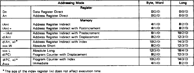
D.2 OPERAND EFFECTIVE ADDRESS CALCULATION TIMING
Table D-1 lists the number of clock periods required to compute an instruction's effective address. It includes fetching of any extension words, the address computation, and fetching of the memory operand. The number of bus read and write cycles is shown in parenthesis as (r/w). Note there are no write cycles involved in processing the effective address.
Table D-1. Effective Address Calculation Times
D.3 MOVE INSTRUCTION EXECUTION TIMES
Tables D-2 and D-3 indicate the number of clock periods for the move instruction. This data includes instruction fetch, operand reads, and operand writes. The number of bus read and write cycles is shown in parenthesis as (r/w).
Table D-2. Move Byte and Word Instruction Execution Times

Table D-3. Move Long Instruction Execution Times

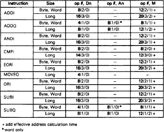
D.4 STANDARD INSTRUCTION EXECUTION TIMES
The number of clock periods shown In Table D-4 Indicates the time required to perform the operations, store the results, and read the next instruction. The number of bus read and write cycles is shown in parenthesis as (r/w). The number of clock periods and the number of read and write cycles must be added respectively to those of the effective address calculation where indicated.
In Table D-4 the headings have the following meanings: An = address register operand, Dn = data register operand, ea = an operand specified by an effective address, and M = memory effective address operand.
Table D-4. Standard Instruction Execution Times

D.5 IMMEDIATE INSTRUCTION EXECUTION TIMES
The number of clock periods shown in Table D-5 includes the time to fetch immediate operands, perform the operations, store the results, and read the next operation. The number of bus read and write cycles is shown in parenthesis as (r/w). The number of clock periods and the number of read and write cycles must be added respectively to those of the effective address calculation where indicated.
In Table D-5, the headings have the following meanings: # = immediate operand, Dn = data register operand, An = address register operand, and M = memory operand. SR = status register.
Table D-5. Immediate Instruction Execution Times
D.6 SINGLE OPERAND INSTRUCTION EXECUTION TIMES
Table D-6 indicates the number of clock periods for the single operand Instructions. The number of bus read and write cycles is shown in parenthesis as (r/w). The number of clock periods and the number of read and write cycles must be added respectively to those of the effective address calculation where indicated.
Table D-6. Single Operand Instruction Execution Times

D.7 SHIFT/ROTATE INSTRUCTION EXECUTION TIMES
Table D-7 indicates the number of clock periods for the shift and rotate instructions. The number of bus read and write cycles is shown in parenthesis as (r/w). The number of clock periods and the number of read and write cycles must be added respectively to those of the effective address calculation where indicated.
Table D-7. Shift/Rotate Instruction Execution Times

D.12 MISCELLANEOUS INSTRUCTION EXECUTION TIMES
Tables D-12 and D-13 Indicate the number of clock periods for the following miscellaneous instructions. The number of bus read and write cycles is shown In parenthesis as (r/w). The number of clock periods plus the number of read and write cycles must be added to those of the effective address calculation where indicated.
Table D-12. Miscellaneous Instruction Execution Times

Table D-13. Move Peripheral Instruction Execution Times

D.13 EXCEPTION PROCESSING EXECUTION TIMES
Table D-14 indicates the number of clock periods for exception processing. The number of clock periods includes the time for all stacking, the vector fetch, and the fetch of the first two Instruction words of the handler routine. The number of bus read and write cycles is shown in parenthesis as (r/w).
Table D-14. Exception Processing Execution Times
