
17
The 16F62X microcontroller
The 16F62X family of microcontrollers includes the two devices 16F627 and 16F628.
The 16F62X microcontrollers are flash devices and have 18 pins and data EEPROM just like the 16F84, but they have more functions. Notably there is an on board oscillator so an external crystal is not required. This frees up two pins for extra I/O. The 16F62X in fact can use 16 of its 18 pins as I/O.
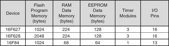
Table 17.1 shows the specification of the 16F62X devices and the 16F84 for comparison.
Table 17.1 The 16F62X specification
16F62X oscillator modes
The 16F62X can be operated in 8 different oscillator modes. They are selected when programming the device just like the 16F84, or by inserting the configuration bits in the header.
| Low Power Crystal, 32.768kHz | |
| 4MHz Crystal | |
| High Speed Crystal, 20MHz | |
| External Resistor (2 modes) | |
| Internal Resistor/Capacitor (2 modes) | |
| External Clock in |
The two modes for the internal resistor/capacitor configuration are 4MHz and 37kHz. The default setting is 4MHz. The 16F627 header, HEAD62RC.ASM, selects the 37kHz oscillator by clearing the OSCF (oscillator frequency) bit, bit3 in the Peripheral Control Register, PCON with BCF PCON,3.
There was obviously a good reason for Microchip choosing 37kHz for the oscillator instead of 32.768kHz, I only wish I knew what it was! 32.768kHz as we have seen before (HEADER84.ASM) can give us TMR0 pulses of 32 a second when setting the option register to divide the program timing pulses by 256.
The most attractive proposition I can see using 37kHz is:
• Program execution frequency is 37kHz/4 = 9250Hz.
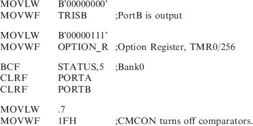
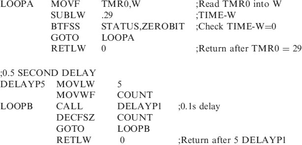
• Setting the prescaler to /32 gives TMR0 pulses of 9250/32 = 289.0625Hz = 0.03459459s for each pulse.
• Counting 29 TMR0 pulses gives a time of 0.100324324s i.e. 0.1s + 0.3% error. If this error, about 4.5 minutes a day, is unacceptable then a 32.768kHz crystal can be used as we did with the 16F84.
Since the programs used previously on the 16F84 did not require any accurate timing our 16F62X header will set the prescaler to divide by 32 and use a subroutine to count 29 TMR0 pulses to give a time of 0.1s.
All of the 16F84 programs can then be transferred to the 16F62X header.
The choice of a 32.768kHz crystal or the 37kHz internal RC will obviously make a difference to the timing routines in the header. I have therefore included two headers for the 16F62X devices. HEAD62LP.ASM for use with the 32kHz crystal and HEAD62RC.ASM for use with the 37kHz internal RC oscillator.

16F62X Port configuration
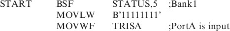
The header (HEAD62RC.ASM) will configure the 16F62X I/O as shown in Figure 17.1.
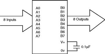
Figure 17.1 The 16F62X port configuration in HEAD62RC.ASM
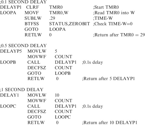
The header (HEAD62LP.ASM) will configure the 16F62X I/O as shown in Figure 17.2.
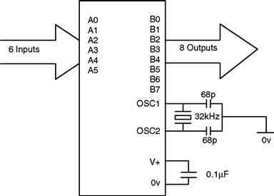
Figure 17.2 The 16F62X port configuration in HEAD62LP.ASM
16F62X Memory map
The 16F62X Memory Map at the end of the chapter (page 256).
The 16F62X headers
HEAD62LP.ASM
| HEAD62LP.ASM using the 32kHz crystal | |
| ;PortA bits 0 to 5 are inputs | |
| ;PortB bits 0 to 7 are outputs | |
| ;Prescaler/256 |
;********************************************
;EQUATES SECTION
| TMR0 | EQU | 1 |
| OPTION_R | EQU | 1 |
| PORTA | EQU | 5 |
| PORTB | EQU | 6 |
| TRISA | EQU | 5 |
| TRISB | EQU | 6 |
| STATUS | EQU | 3 |
| ZEROBIT | EQU | 2 |
| CARRY | EQU | 0 |
| EEADR | EQU | 1BH |
| EEDATA | EQU | 1AH |
| EECON1 | EQU | 1CH |
| EECON2 | EQU | 1DH |
| RD | EQU | 0 |
| WR | EQU | 1 |
| WREN | EQU | 2 |
| COUNT | EQU | 20H |
;*****************************************************
| LIST | P=16F627 | ;using the 627 |
| ORG | 0 | |
| GOTO | START |
;*******************************************************
| __CONFIG H′3F00′ | ;selects LP oscillator, WDT off, |
| ;Code Protection disabled. |
;*******************************************************
;SUBROUTINE SECTION.
;**********************************************************
;CONFIGURATION SECTION.
;*********************************************************
END
HEAD62RC.ASM
| ;HEAD62RC.ASM using the 37kHz internal RC | |
| ;PortA bits 0 to 7 are inputs | |
| ;PortB bits 0 to 7 are outputs | |
| ;Prescaler/32 |
;********************************************
;EQUATES SECTION
| TMR0 | EQU | 1 |
| OPTION_R | EQU | 1 |
| PORTA | EQU | 5 |
| PORTB | EQU | 6 |
| TRISA | EQU | 5 |
| TRISB | EQU | 6 |
| STATUS | EQU | 3 |
| ZEROBIT | EQU | 2 |
| CARRY | EQU | 0 |
| EEADR | EQU | 1BH |
| EEDATA | EQU | 1AH |
| EECON1 | EQU | 1CH |
| EECON2 | EQU | 1DH |
| RD | EQU | 0 |
| WR | EQU | 1 |
| WREN | EQU | 2 |
| PCON | EQU | 0EH |
| COUNT | EQU | 20H |
;*****************************************************
| LIST | P=16F627 | ;using the 627 |
| ORG | 0 | |
| GOTO | START |
;*******************************************************
| __CONFIG H′3F10′ | ;selects Internal RC oscillator, WDT off, |
| ;Code Protection disabled. |
;*******************************************************
;SUBROUTINE SECTION.
;************************************************************
;CONFIGURATION SECTION.

;*********************************************************
A 16F627 application – flashing an LED on and off
In order to introduce the operation of the 16F672 device we will consider the simple example of the single LED flashing on and off, which was introduced in Chapter 2.
The 16F627 will be operated in the INTRC mode using the internal 37kHz oscillator.
The circuit diagram for this is shown in Figure 17.3.
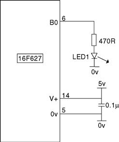
Figure 17.3 The 16F627 LED flashing circuit
The 16F627 LED flasher code
| ;FLASH_RC.ASM using the 37kHz internal RC | |
| ;PortA bits 0 to 7 are inputs | |
| ;PortB bits 0 to 7 are outputs | |
| ;Prescaler/32 |
;********************************************
;EQUATES SECTION
| TMR0 | EQU | 1 |
| OPTION_R | EQU | 1 |
| PORTA | EQU | 5 |
| PORTB | EQU | 6 |
| TRISA | EQU | 5 |
| TRISB | EQU | 6 |
| STATUS | EQU | 3 |
| ZEROBIT | EQU | 2 |
| CARRY | EQU | 0 |
| EEADR | EQU | 1BH |
| EEDATA | EQU | 1AH |
| EECON1 | EQU | 1CH |
| EECON2 | EQU | 1DH |
| RD | EQU | 0 |
| WR | EQU | 1 |
| WREN | EQU | 2 |
| PCON | EQU | 0EH |
| COUNT | EQU | 20H |
;*****************************************************
| LIST | P=16F627 | ;using the 627 |
| ORG | 0 | |
| GOTO | START |
;*******************************************************
;Configuration Bits
| __CONFIG H′3F10′ | ;selects Internal RC oscillator, WDT off, |
| ;Code Protection disabled. |
;*******************************************************
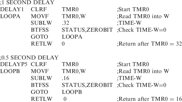
;SUBROUTINE SECTION.
![]()
;******************************************************************
;*********************************************************
;Program starts now.
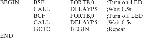
The operation of the program after ‘Program starts now’, is exactly the same as in FLASHER.ASM in Chapter 2, using the 16F84.
All of the programs using the 16F84 can be transferred by copying the code starting at ‘Program starts now’ and pasting into HEAD62RC.ASM or HEAD62LP.ASM as required.
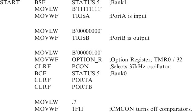
Configuration settings for the 16F627
When programming the Code FLASH_RC.HEX into the 16F627 use the configuration settings shown in Figure 17.4. This setting equates to H’3F10’ which can be written into the Configuration Bits setting in your code.

Figure 17.4 Configuration settings for FLASH_RC.HEX
Other features of the 16F62X
The 16F62X also includes,
• An analogue comparator module with 2 analogue comparators and an on-chip voltage reference module.
• Timer1 a 16 bit timer/counter module with external crystal/clock capability and Timer2 an 8 bit timer/counter with prescaler and postscaler.
Please refer to the 16F62X data sheet for operation of these other features.
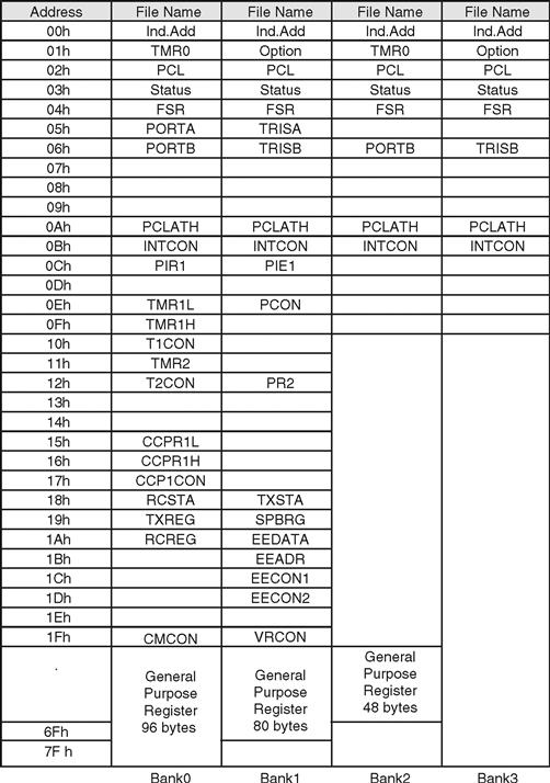
The 16F62X memory map