
12
Radio transmitters and receivers
Radio circuits used to frighten me but now with the introduction of low cost modules the radio novice like myself can transmit data easily.
This section details the use of the 418 MHz Radio Transmitter and Receiver Modules (RT1-418 and RR3-418). They do not need a license to operate and there are many varieties available. The transmitters only have 3 connections, 2 power supply and one data input, the transmitting aerial is incorporated on the unit. The receiver has 4 connections, 2 power supply, 1 aerial input and 1 data output. The receiving aerial only needs to be a piece of wire about 25cm long.
The basic circuit diagram of the radio system is shown in Figure 12.1.
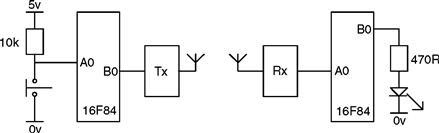
Figure 12.1 Radio data transmission system
The microcontroller generates the data and then passes the data pulses to the transmitter. The receiver receives the data pulses and a microcontroller decodes the information and processes it.
A microcontroller-radio system could measure the temperature outside and transmit this temperature to be displayed on a unit inside.
How does it work?
The transmitter
Data is generated by the microcontroller say by pressing a switch or from a temperature sensor via the 16F818 doing an A/D conversion. Suppose this data is 27H, this would then be stored in a user file, called, say, NUMA.
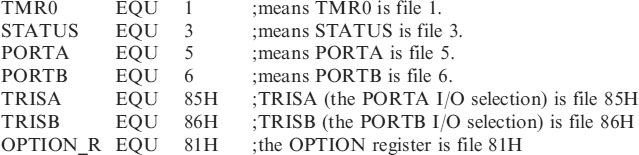
So file NUMA would appear as shown in Figure 12.2.
![]()
Figure 12.2 File NUMA containing 27H
The data then needs to be passed from the micro to the data input of the transmitter. The transmitter output will then be turned on and off by the data pulses. The length of time the transmitter is on will indicate if the data was a 1, a 0 or the transmission start pulse.
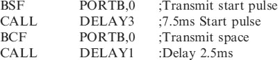
I have decided to use a start bit that is 7.5ms wide, a 5ms pulse to represent a logic 1 and a 2.5ms pulse to represent a logic 0. All pulses are separated by a space of 2.5ms. The pulse train for NUMA is then as shown in Figure 12.3.

Figure 12.3 NUMA pulse train
In order to generate this train the software turns the output on for the 7.5ms start pulse, off for 2.5ms, on for 5ms for the first 1, off for 2.5ms, on for 5ms for the next logic 1, off for 2.5ms, on for 5ms for the next logic 1, off for 2.5ms, on for 2.5ms for the logic 0, etc.
To generate the data each bit in the file NUMA is tested in turn. If the bit is 0 then the output is turned on for 2.5ms, if the bit is 1 then the output is turned on for 5ms. The code for this data would be:
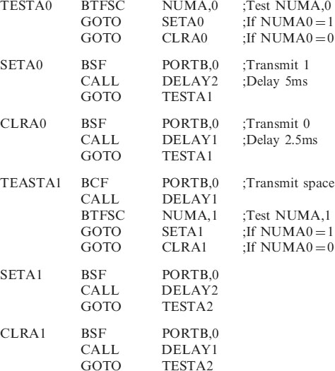
This bit testing is repeated until all 8 bits are transmitted.
The receiver
The receiver works the opposite way round. The data is received and stored in a file NUMA. Several data bytes could be transmitted depending on how many switches are used. Or the data may be continually varying from a temperature sensor. In this example we are only looking for one byte i.e. the number 27H which was transmitted. The data is passed from the receiver to the input A0 of the microcontroller.
We wait to receive the 7.5ms start bit. When this is detected we then measure the next 8 pulses.
If a pulse is 5ms wide then a one has been transmitted and we SET the relative bit in the file NUMA. If the pulse is only 2.5ms long then we leave the bit CLEAR.
Measuring the received pulse width
Measuring the width of a pulse is a little more difficult than setting a pulse width. Consider the pulse in Figure 12.4.

Figure 12.4 Measuring the width of a pulse
The input is continually tested until it goes high and then the timer, TMR0, is cleared to start timing. The input is continually tested until it goes low and then the value of TMR0 is read. This is done by:
| MOVF | TMR0,W which puts the value of TMR0 into W. |
We can then check to see if the pulse is 5ms long i.e. a logic 1, if not then a shorter pulse means a logic 0 was transmitted. If the pulse is greater than 3.5ms then it must be a logic1, at 5ms. If the pulse is less than 3.5ms then it must be a logic0. TMR0 will hold a value of 3 after a time of 3.5ms, so we check to see if the width of the pulse is greater or less than 3.
The code for this is:

This measuring of the pulse width continues until all 8 pulses are read and the relevant bits stored in the file NUMA. A TMR0 value >6 indicates the pulse was a Start pulse.
We then check to see if the number stored in the file NUMA is 27H. This is done as we have done before by subtracting 27H from it, if the answer is zero, i.e. 27−27 = 0, then the number transmitted was 27H and we turn on the LED. It seems such a waste to go to all this trouble to turn an LED on. I hope you can be a little more imaginative − this is only an example.
The complete codes for the transmitter and receiver are shown below as TX.ASM and RX.ASM.
The OPTION register has been set to produce timing pulses of 1ms.
Transmitter program code
;tx.asm transmits code from a switch.

;*********************************************************
| LIST | P = 16F84 | ; we are using the 16F84. |
| ORG | 0 | ;the start address in memory is 0 |
| GOTO | START | ; goto start! |
;**********************************************************
;Configuration Bits
| __CONFIG H′3FF0′ | ;selects LP oscillator, WDT off, PUT on, |
| ; Code Protection disabled. |
;*********************************************************

;**********************************************************
;CONFIGURATION SECTION
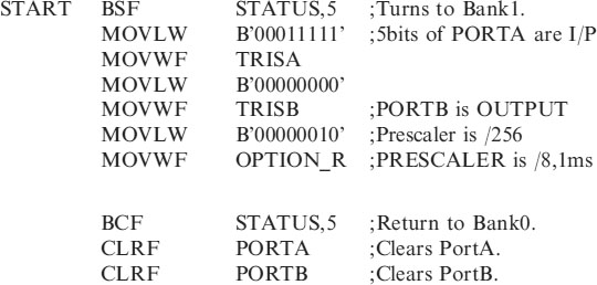
;*********************************************************


Receiver program code:

;*********************************************************
| LIST | P = 16F84 | ;we are using the 16F84. |
| ORG | 0 | ;the start address in memory is 0 |
| GOTO | START | ;goto start! |
;**********************************************************
| __CONFIG H′3FF0′ | ;selects LP oscillator, WDT off, PUT on, |
| ;Code Protection disabled. |
;**********************************************************
;CONFIGURATION SECTION.

;*********************************************************
;Program starts now.


Using the transmit and receive subroutines
The transmit and receive subroutines may seem a little complex, but all you need to do in your code is call them.
• To transmitPut the data you wish to transmit in the file NUMA then CALLTRANSMIT. The data in the file NUMA is transmitted.
• To receiveCALL RECEIVE, the received data will be present in the file NUMA for you to use.
These programs have illustrated how to switch an LED on (this could be a remote control for a car burglar alarm). You may of course want to add more lines of code to be able to turn the LED off. This could be done in the receiver section by waiting for say 2 seconds and on the next transmission turn the LED off, providing of course the code was again 27H. Other codes could of course be added for other switches or keypad buttons, the possibilities are endless.
The transmitter and receiver micros could be hard wired together first to test the software without the radio link. The radio transmitter and receiver can then replace the wire to give a wireless transmission.