
2
Programming the 16F84 microcontroller
Microcontrollers are now providing us with a new way of designing circuits. Designs, which at one time required many Digital ICs and lengthy Boolean Algebra calculations, can now be programmed simply into one Micro controller. For example a set of traffic lights would have required an oscillator circuit, counting and decoding circuits plus an assortment of logic gate ICs.
In order to use this exciting new technology we must learn how to program these Microcontrollers.
The Microcontroller I have chosen to start with is the 16F84-04/P, which means it is a flash device that can be electrically erased and reprogrammed without using an Ultra Violet Eraser. It can be used up to an oscillation frequency of 4MHz and comes in a standard 18pin Plastic package.
It has 35 instructions in its vocabulary, but like all languages not all of the instructions are used all of the time you can go a long way on just a few. In order to teach you how to use these instructions I have started off with a simple program to flash an LED on and off continually. This program introduces you to 4 instructions in 5 lines of code.
You are then encouraged to write your own program to flash two LEDs on and off alternately. The idea being, when you have understood my code you can then modify it for your own program, thus understanding better. Once you have written your first program you are then off and running. The book then continues with further applications such as traffic lights and disco lights to introduce more of the instructions increasing your microcontroller vocabulary.
Microcontroller inputs and outputs (I/O)
The microcontroller is a very versatile chip and can be programmed to operate in a number of different configurations. The 16F84 is a 13 I/O device, which means it has 13 Inputs and Outputs. The I/O can be configured in any combination i.e. 1 input 12 outputs, 6 inputs 7 outputs, or 13 outputs depending on your application. These I/O are connected to the outside world through registers called Ports. The 16F84 has two ports, PORTA and PORTB. PORTA is a 5-bit port it has 5 I/O lines and PORTB has 8 I/O.
Timing with the microcontroller
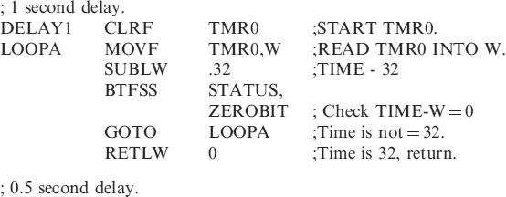
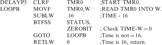
All microcontrollers have timer circuits onboard; some have 4 different timers. The 16F84 has one timer register called TIMER0. These timers run at a speed of ¼ of the clock speed. So if we use a 32,768Hz crystal the internal timer will run at ¼ of 32768Hz i.e. 8192Hz. If we want to turn an LED on for say 1 second we would need to count 8192 of these timing pulses. This is a lot of pulses! Fortunately within the microcontroller there is a register called an OPTION Register, that allows us to slow down these pulses by a factor of 2, 4, 8, 16, 32, 64, 128 or 256. The OPTION Register is discussed in the Instruction Set, Files and Register section in Chapter 19. Setting the prescaler, as it is called to divide by 256 in the OPTION register means that our timing pulses are now 8192/256 = 32Hz, i.e. 32 pulses a second. So to turn our LED on for 1 second we need only to count 32 pulses in TIMER0, or 16 for 0.5 seconds, or 160 for 5 seconds etc.
Programming the microcontroller
In order to program the microcontroller we need to:
• Write the instructions in a program.
• Change the text into machine code that the microcontroller understands using a piece of software called an assembler.
Let's consider the first task, writing the program. This can be done on any text editor, such as notepad. I prefer to use an editor supplied by the microcontroller manufacturers, ‘Microchip’. This software is called MPLAB and is available free on www.microchip.com.
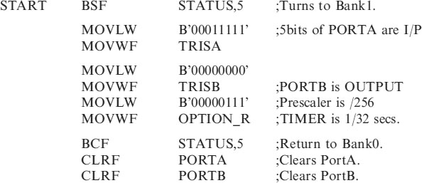
As you have seen above we need to configure the I/O and set the Prescaler for the timing. If we do not set them the default conditions are that all PORT bits are inputs. A micro with no outputs is not much use! The default for the Prescaler is that the clock rate is divided by 2.
The program also needs to know what device it is intended for and also what the start address in the memory is.
If this is starting to sound confusing – do not worry, I have written a header program, which sets the all the above conditions for you to use. These conditions can be changed later when you understand more about what you are doing.
The header for the 16F84 sets the 5 bits of PORTA as inputs and the 8 bits of PORTB as outputs. It also sets the prescaler to divide by 256. We will use the 32,768Hz crystal so our timing is 32 pulses per sec. The program instructions will run at ¼ of the 32,768Hz clock, i.e. 8192 instructions per second. The header also includes two timing subroutines for you to use they are DELAY1 – a 1 second delay and DELAYP5 – a half-second delay. A subroutine is a section of code that can be called, when needed, to save writing it again. For the moment do not worry about how the header or the delay subroutines work. We will work through them, in Chapter 6, once we have programmed a couple of applications.
Just one more point, the different ways of entering data.
Entering data
Consider the decimal number 37, this has a Hex value of 25 or a Binary value of 0010 0101. The assembler will accept this as .37 in decimal (note the . is not a decimal point) or as 25H in hex or B’00100101’ in binary.
181 decimal would be entered as .181 in decimal, 0B5H in hex or B’10110101’ in binary. NB. If a hex number starts with a letter it must be prefixed with a 0, i.e. 0B5H not B5H.
NB. The default radix for the assembler MPASM is hex.
Appendix C. illustrates how to change between Decimal, Binary and Hexadecimal numbers.
The PIC Microcontrollers are 8 bit micros. This means that the memory locations, i.e. user files and registers contain 8 bits. So the smallest 8 bit number is of course 0000 0000 which is equal to a decimal number 0 (of course). The largest 8 bit number is 1111 1111 which is equal to a decimal number of 255. To use numbers bigger than 255 we have to combine memory locations. Two memory locations combine to give 16 bits with numbers up to 65,536. Three memory locations combine to give 24 bits allowing numbers up to 16,777,215 and so on. These large numbers are introduced in Chapter 8, Numbers Larger than 255.
The Header for the 16F84, HEADER84.ASM
The listing below shows the header for the 16F84 microcontroller. I suggest you start all of your programs, for this chip, with this header, or a modified version of it. A full explanation of this header file is given in Chapter 6.
; HEADER84.ASM for 16F84. This sets PORTA as an INPUT (NB 1means input).
; and PORTB as an OUTPUT (NB 0 means output).
; The OPTION Register is set to /256 to give timing pulses of 1/32 of a second.
;1second and 0.5 second delays are included in the subroutine section.
;*********************************************************
; EQUATES SECTION

;*********************************************************
| LIST | P = 16F84 | ; we are using the 16F84. |
| ORG | 0 | ;the start address in memory is 0 |
| GOTO | START | ; goto start! |
;******************************************************************
; Configuration Bits
| __CONFIG H’3FF0’ | ;selects LP oscillator, WDT off, PUT on, |
| ;Code Protection disabled. |
;*********************************************************
;SUBROUTINE SECTION.
;*********************************************************
;*********************************************************
;Program starts now.
| END | ;This must always come at the end of your code |
NB. In the program any text on a line following the semicolon (;) is ignored by the assembler software. Program comments can then be placed there.
The section is saved as HEADER84.ASM you can use it to start all of your 16F84 programs. HEADER84 is the name of our program and ASM is its extension.
Program example
The best way to begin to understand how to use a microcontroller is to start with a simple example and then build on this.
Let us consider a program to flash an LED ON and OFF at 0.5 second intervals. The LED is connected to PortB bit 0 as shown in Figure 2.1.
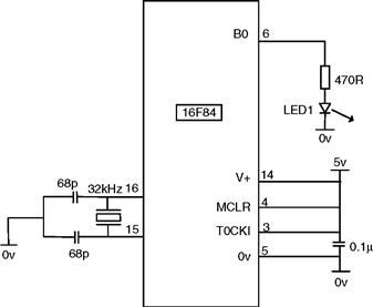
Figure 2.1 Circuit diagram of the microcontroller flasher
Notice from Figure 2.1 how few components the microcontroller needs – 2 × 68pF capacitors, a 32.768kHz crystal for the oscillator and a 0.1μF capacitor for decoupling the power supply. Other oscillator and crystal configurations are possible – see Microchip's data sheets for other combinations. I have chosen the 32kHz crystal because it enables times of seconds to be produced easily.
The program for this circuit can be written on any text editor, such as Notepad or on Microchip's editor MPLAB.
Open HEADER84.ASM or start a new file and type the program in, saving as HEADER84.ASM If using Notepad saveas type “All Files” to avoid Notepad adding the extension .TXT
Once you have HEADER84.ASM saved on disk and loaded onto the screen alter it by including your program as shown below:-
; HEADER84.ASM for 16F84. This sets PORTA as an INPUT (NB 1means input).
; and PORTB as an OUTPUT (NB 0 means output).
;The OPTION Register is set to /256 to give timing pulses of 1/32 of a second.
;1second and 0.5 second delays are included in the subroutine section.
;*******************************************************
; EQUATES SECTION
;*********************************************************
| LIST | P = 16F84 | ;we are using the 16F84. |
| ORG | 0 | ;the start address in memory is 0 |
| GOTO | START | ;goto start! |
;******************************************************************
; Configuration Bits
| __CONFIG H’3FF0’ | ;selects LP oscillator, WDT off, PUT on, |
| ;Code Protection disabled. |
;*****************************************************
;SUBROUTINE SECTION.


;*********************************************************

;*********************************************************
;Program starts now.

How Does It Work?
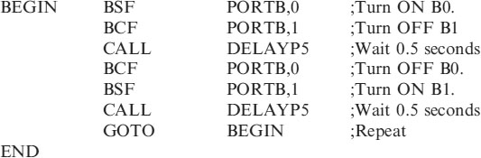
The 5 lines of code starting at BEGIN are responsible for flashing the LED ON and OFF. This is all the code we will require for now. The rest of the code, the header is explained in Chapter 6 once you have seen the program working.
• BEGIN is a label. A label is used as a location for the program to go to.
• Line1 the instruction BSF and its data PORTB,0 is shorthand for Bit Set in File, which means Set the Bit in the File PORTB, where bit0 is the designated bit. This will cause PORTB,0 to be Set to a logic1, in hardware terms this means pin6 in Figure 2.1 is at 5v turning the LED on.
NB. There must not be any spaces in a label, an instruction or its data. I keep the program tidy by using the TAB key on the keyboard.
• Line2 CALL DELAYP5 causes the program to wait 0.5 seconds while the subroutine DELAYP5 in the header is executed.
• Line3 BCF PORTB,0 is the opposite of Line1, this code is shorthand for Bit Clear in File, which means Clear the Bit in the File PORTB, where bit0 is the designated bit. This will cause PORTB,0 to be Cleared to a logic0, in hardware terms this means pin6 in Figure 2.1 is at 0v turning the LED off.
• Line4 CALL DELAYP5 is the same as Line2.
• Line5 GOTO BEGIN sends the program back to the label BEGIN to repeat the process of flashing the LED on and off.
Any of the 8 outputs can be turned ON and OFF using the 2 instructions BSF and BCF for example:
Saving and assembling the code
The program is then saved as FLASHER.ASM. The next task is to assemble this text into the HEX code that the microcontroller understands.
Open MPLAB the screen shown below in Figure 2.2 will open up.
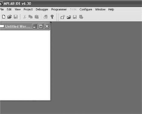
Figure 2.2 MPLAB initial screen
Open the file FLASHER.ASM using the FILE menu as shown in Figure 2.3.
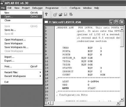
Figure 2.3 Opening FLASHER.ASM
From the CONFIGURE Menu, Select Device then choose the micro 16F84 in this example, as indicated in Figure 2.4.
Figure 2.4 CONFIGURE –; select device
Next choose CONFIGURE – Configuration Bits as shown in Figure 2.5 and set as indicated.
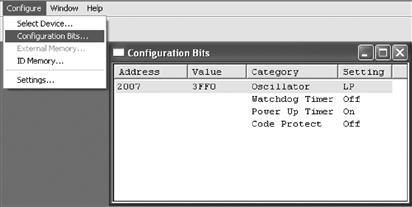
Figure 2.5 Configuration bits setting
Our configuration bits setting, select the LP Oscillator, turn the Watchdog Timer Off, turn the Power Up Timer on and turn Code Protect off.
Notice the value of this configuration is 3FF0 in hex. This configuration setting can be written into the header program so there is no need to here. The code is __CONFIG H’3FF0’
The choice of configuration bit settings for the 16F84 are:
• the Oscillator, RC, LP, XT, HS. i.e. LP
• Watchdog Timer ON/OFF i.e. OFF
Then we have to convert our text, FLASHER.ASM into a machine code file FLASHER.HEX to do this choose PROJECT – Quickbuild Flasher.ASM as shown in Figure 2.6.
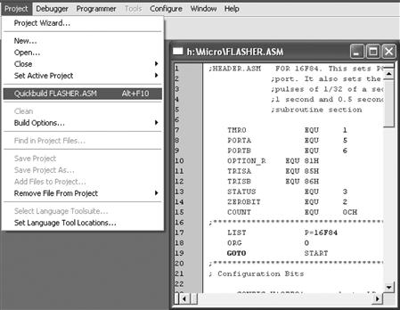
Figure 2.6 Compiling FLASHER.ASM to FLASHER.HEX
If the program has compiled without any errors then MPLAB will return with a message Build Succeeded as indicated in Figure 2.7. There may be some warnings and messages but do not worry about them, the compiler has seen something it wasn't expecting.
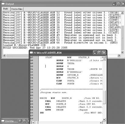
Figure 2.7 Build Succeeded
Incidently, I always have line numbers on my code to find my way around, especially in larger programs. Line numbers can be turned on and off with the path: EDIT – PROPERTIES.
Suppose that you have a syntax error in your code. The message Build Failed will appear as shown in Figure 2.8. You then have to correct the errors. MPLAB has indicated the error in the message box. If you ‘double click’ on the error message then MPLAB will indicate, with an arrow, where the error is in your code. Correct the errors and compile (Quickbuild) again to produce an error free build.

Figure 2.8 Build failed
The error I have written into my code occurs in line 61, with the message, ‘symbol not previously defined (PORT)’. I should have written PORTB the compiler does not understand ‘PORT’.
After successfully building the program, the HEX code is ready to be programmed into the Microcontroller.
You can view your compilation using VIEW – PROGRAM MEMORY as shown in Figure 2.9.

Figure 2.9 Program memory
The FLASHER.HEX file is now ready to be programmed into the chip.
PICSTART PLUS programmer
If you do not have a programmer I would recommend Arizona Microchip's own PICSTART PLUS. When Arizona bring out a new microcontroller as they do regularly, the driver software is updated and can be downloaded free off the internet from MICROCHIP.COM.
Once installed on your PC it is opened from MPLAB i.e.
Switch on the PICSTART Plus Programmer.
Select, Programmer – Select Programmer – PICSTART Plus, shown in Figure 2.10.
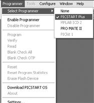
Figure 2.10 Selecting the PICSTART plus programmer
Select Enable Programmer from the Programmer box, Figure 2.10.
The final stage is to program your code onto the chip. To do this click the programming icon shown in Figure 2.11 or via the menu on Programmer – Program.
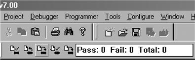
Figure 2.11 Programming icon
After a short while the message success will appear on the screen.
You will be greeted with the success statement for a few seconds only, if you miss it check the program statistics for Pass 1 Fail 0 Total 1, which will be continually updated.
The code has been successfully blown into your chip and is ready for use.
If this process fails – check the chip is inserted correctly in the socket, if it is then try another chip.
So we are now able to use the microcontroller to switch an LED on and off – Fantastic!
But use your imagination. There are 35 instructions in your micro vocabulary. The PIC Microcontroller range at the moment includes devices with 64k bytes of EPROM-program memory, 3938 bytes of RAM-data memory, 1024 bytes of EEPROM, 72 Input and Output pins, 11 interrupts, 15 channel A/D converter, 20MHz. clock, real time clock, 4 counter/timers, 55 word instruction set. See Appendix A for a detailed list. If the 64k of EPROM or 3938 bytes of RAM is not enough your system can be expanded using extra EPROM and RAM. In the end the only real limits will be your imagination.

Problem: flashing two LEDs
There has been a lot to do and think about to get this first program into the microcontroller and make it work in a circuit. But just so that you are sure what you are doing – Write a program that will flash two LEDs on and off alternately. Put LED0 on B0 and LED1 on B1. NB you can use the file FLASHER.ASM it only needs two extra lines adding! Then save it as FLASHER2.ASM
The circuit layout is shown in Figure 2.12.
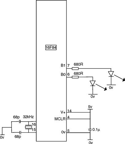
Figure 2.12 Circuit to flash 2 LEDs
Try not to look at the solution below before you have attempted it.
Solution to the problem, flashing two LEDs
The header is the same as in FLASHER.ASM. just include in the section, program starts now, the following lines:
;Program starts now.
Did you manage to do this? If not have a look at my solution and see what the lines are doing. Now try flashing 4 LEDs on and off, with 2 on and two off alternately. You might like to have them on for 1 second and off for half a second. Can you see how to use the 1-second delay in place of the half-second delay.
The different combinations of switching any 8 LEDs on PORTB should be relatively easy once you have mastered these steps.
Perhaps the most difficult step in understanding any new technology is getting started. The next chapter will introduce a few more projects similar to Flasher.ASM to help you progress.