
19
Instruction set, files and registers
Microcontrollers work essentially by manipulating data in memory locations. Some of these memory locations are special registers others are user files. In a control application data may be read from an input port, manipulated and passed to an output port.
To use the microcontroller you need to know how to move and manipulate this data in the memory. There are 35 instructions in the PIC 16F84 to enable you to do this. Using the Microcontroller is then about using these instructions in a program. Like any vocabulary you do not use all the words all of the time, some you never use others only now and again. The PIC Instruction Set is like this – you can probably manage quite well with say 15 instructions.
Most of these instructions involve the use of the WORKING REGISTER or Wreg. The W register is at the heart of the PIC Microcontroller. To move data from File A to File B you have to move it from File A to W and then from W to File B, rather like a telephone system routes one caller to another via the exchange. The W reg also does the arithmetic and logical manipulating on the data.
The PIC microcontroller instruction set
To communicate with the PIC microcontroller you have to learn how to program it using its instruction set. The 16F84 chip has a 1k × 14 bit word EEPROM program memory, 68 × 8bit general purpose registers and a 35 word instruction set made up of three groups of instructions, bit, byte and literal and control operations.
The instructions can be sub-divided into 3 types:
• Bit Instructions, which act on 1 bit in a file.
• Byte Instructions, which act on all 8 bits in a file.
• Literal and Control Operations, which modify files with variables or control the movement of data from one file to another.
Bit instructions
The bit instructions act on a particular bit in a file, so the instruction would be followed by the data which specifies the file number and bit number.
I.e. BSF 6,3 This code is not too informative so we would use something like BSF PORTB, BUZZER where PORTB is file 6 and the buzzer is connected to bit 3 of the output port. In the equates section we would see PORTB EQU 6 and BUZZER EQU 3.
| BCF | Bit Clear in File. |
| BSF | Bit Set in File. |
| BTFSC | Bit Test in File Skip if Clear. |
| BTFSS | Bit Test in File Skip if Set. |
Byte instructions
Byte instructions work on all 8 bits in the file. So a byte instruction would be followed by the appropriate file number.
I.e. DECF 0CH. This statement is not too informative so we would again indicate the name of the file such as DECF COUNT. Of course we would need to declare in the equates section that COUNT was file 0CH, by COUNT EQU 0CH.
| ADDWF | ADD W and F. |
| ANDWF | AND W and F. |
| CLRF | CLeaR File. |
| CLRW | CLeaR Working register. |
| COMF | COMplement File. |
| DECF | DECrement File. |
| DECFSZ | DECrement File Skip if Zero. |
| INCF | INCrement File. |
| INCFSZ | INCrement File Skip if Zero. |
| IORWF | Inclusive-OR W and F. |
| MOVF | MOVe F to W. |
| MOVWF | MOVe W to F. |
| NOP | No OPeration. |
| RLF | Rotate File one place Left. |
| RRF | Rotate File one place Right. |
| SUBWF | SUBtract W from F. |
| SWAPF | SWAp halves of F. |
| XORWF | eXclusive-OR W and F. |
Literal and control operations
Literal and control operations manipulate data and perform program branching (jumps).
| ADDLW | ADD Literal with W. |
| ANDLW | AND Literal with W. |
| CALL | CALL subroutine. |
| CLRWDT | CLeaR watchdog Timer. |
| GOTO | GOTO address. |
| IORLW | Inclusive-OR Literal with W. |
| MOVLW | MOVe Literal to W. |
| RETFIE | RETurn From IntErrupt. |
| RETLW | RETurn place Literal in W. |
| RETURN | RETURN from subroutine. |
| SLEEP | Go into standby mode. |
| SUBLW | SUBtract Literal from W. |
| XORLW | eXclusive-OR Literal and W. |
These instructions operate mainly on two 8 bit registers – the Working register or W register and a File F which can be one of the 15 special registers or one of the 68 general purpose file registers which form the user memory (RAM) of the 16F84.
The memory map of the 16F84 is shown in Figure 6.1.
The PIC Microcontrollers are 8 bit devices – this means that the maximum number that can be stored in any one memory location is 255. Some PICs like the 17C43 have 454 bytes of data memory. So to address memory locations greater than 255 the idea of pages or Banks has been introduced. Bank0 holds address locations up to 255, while Bank1 can hold a further 255 and Bank2 a further 255 etc. So you need to know what Bank a particular register or file is in.
Banks are not used in the 16C54.
Registers
Registers are made up of 8 bits as shown in Figure 19.1.
![]()
Figure 19.1 Register layout
Bit 0 is the Least Significant Bit (LSB) and Bit 7 is the Most Significant Bit (MSB).
Register 01 TMR0, TIMER 0/counter register
This register can be written to or read like any other register. It is used for counting or timing events. The contents of the register can be incremented (add 1) by the application of an external pulse applied to the TOCKI pin i.e. counting cars into a car park or by the internal instruction cycle clock which runs at ¼ of the crystal frequency to time events.
Register 02 PCL, program counter
The Program Counter automatically increments to execute program instructions. An application of the use of the Program Counter is illustrated in the section on the Look Up Table, in Chapter 8.
Register 03, status register
The Status Register contains the result of the arithmetic or logical operations of the program. The 8 bits of the Status Register are shown in Figure 19.2.
![]()
Figure 19.2 Status Register
• Bit 0, C, Carry Bit. This is (set to a 1) if there is a carry from an addition or subtraction instruction.E.g. if one 8 bit number is added to another;
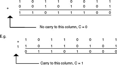
If the result of a subtraction is +ve or zero then the carry bit is set.If the result of a subtraction is −ve then the carry bit is clear.
• Bit 2, Z, Zero Bit. This is set if the result of an arithmetic or logic operation is zero. i.e. countdown to zero.An important use of this bit is checking if a variable in memory is equal to a fixed value. I.e. does file CARS contain 150.
| MOVLW | .150 | ;Put 150 in W |
| SUBWF | CARS,W | ;Subtract W from CARS, i.e. CARS-150 |
| BTFSS | STATUS, ZEROBIT | ;Zerobit set if CARS = 150 |
• Bits 6 and 5, RP1 and RP0, are the bank select bits to address banks 0,1,2 and 3 to select the different registers and user files.00 would select bank0, 01 selects bank1, 10 selects bank2 and 11 selects bank3.
Register 04 FSR file select register
The file select register is used in conjunction with the Indirect Data Addressing Register, Register 00. They are used in indirect addressing to read or write data not from a specific file, but to or from a file indicated by the data in the file select register.
Register 05 PORT A and register 06 PORT B
Ports are the pin connections that allow the microcontroller to communicate with its surroundings. Port A is a 5 bit port on the 16F84, only the 5 LSB's are used. Port A bit0 can also be programmed to be a clock input (T0CKI). Port B is an 8 bit port. To set up a port the instruction TRIS is used. Tris is an abbreviation for tristate, three states which can be a high impedance input, a high (5v) output or a low (0v) output.
Register 8FH oscillator control register (16F818)
The oscillator control register is used to select the clock frequency when using the internal oscillator.
| bit 6–4 | IRCF2:IRFC0: Internal Oscillator Frequency Select Bits. |
| 111 = 8 MHz (8MHz source drives clock directly) | |
| 110 = 4 MHz | |
| 101 = 2 MHz | |
| 100 = 1 MHz | |
| 011 = 500 kHz | |
| 010 = 250 kHz | |
| 001 = 125 kHz | |
| 000 = 31.25 kHz (INTRC source drives clock directly) | |
| bit2 | IOFS:INTOSC Frequency Stable Bit. |
![]()
Figure 19.3 Oscillator control register
W Register
The W register holds the result of an operation or an internal data transfer. It is like a telephone exchange – data comes into the W register and is transferred out to another file.
Option Register
This register is used to prescale the Real Time Clock/Counter. TMR0 clock runs at ¼ of the crystal frequency but can be divided down by the prescaler for longer time measurements.
Stack
Stack is the name given to the memory location that keeps track of the program address when a Call instruction is made. There is an eight level stack in the 16F84, which means that the program can jump to a subroutine and from there jump to another subroutine, making 8 jumps in total and the stack will be able to return it back to the program. The 16C54 has a two level stack.
Instruction set summary
| ADDLW | Adds a number (literal) to W. | ||||||
| E.g. ADDLW 7 will add 7 to W, the result is placed in W. | |||||||
| ADDWF | Adds the contents of W to F. | ||||||
| E.g. ADDWF 7 will add the contents of the W register and file 7 | |||||||
| N.B. the result is placed in file 7. | |||||||
| E.g. ADDWF 7,W the result is placed in W. | |||||||
| Status affected C,DC,and Z. | |||||||
| ANDLW | The contents of W are ANDed with an 8 bit number (literal). | ||||||
| The result is placed in W. | |||||||
| E.g. ANDLW 12H or ANDLW | |||||||
| Status affected Z. | |||||||
| ANDWF | The contents of W are ANDed with F. | ||||||
| E.g. ANDWF 12,W the contents of file 12 is ANDed to the contents of W.N.B. The result is placed in W. | |||||||
| E.g. ANDWF 12 the result is placed in file 12. | |||||||
| Status affected Z. | |||||||
| BCF | Clear the bit in file F. | ||||||
| E.g. BCF 6,4 bit 4 is cleared in file 6. | |||||||
| File 6 is port B this clears bit 4, i.e. bit 4 = 0. | |||||||
| BSF | Set bit in file F. | ||||||
| E.g. BSF 6,4 this sets bit 4 in File 6, i.e. bit 4 = 1. | |||||||
| BTFSC | Test bit in file skip if clear. | ||||||
| E.g. BTFSC 3,2 this tests bit 2 in file 3 if it is clear then the next instruction is missed. File 3 is the status register bit 2 is the zero bit so the program jumps if the result of an instruction was zero. | |||||||
| BTFSS | Test bit in file skip if set. | ||||||
| E.g. BTFSS 3,2 if bit 2 in file 3 is set then the next instruction is skipped. | |||||||
| CALL | This calls a subroutine in a program. | ||||||
| E.g. CALL WAIT1MIN This will call a routine (you have written) to wait for 1 minute. May be to turn a lamp on for 1 minute, and then return back to the program. | |||||||
| CLRF | This clears file F i.e. all 8 bits in file F are cleared. | ||||||
| E.g. CLRF 5. | |||||||
| Status affected Z. | |||||||
| CLRW | This clears the W register. | ||||||
| Status affected Z. | |||||||
| CLRWT | The watchdog timer is cleared. The watchdog is a safety device in the microcontroller if the program crashes the watchdog timer times out then restarts the program. | ||||||
| Status affected TO, PD. | |||||||
| COMF | The 8 bits in file F are complemented i.e. inverted. | ||||||
| E.g. COMF 6. | |||||||
| Status affected Z. | |||||||
| DECF | Subtract 1 from file F. Useful for counting down to zero. | ||||||
| E.g. DECF 12 will store the result in 12. | |||||||
| DECF 12,W will store the result in W leaving 12 unchanged. | |||||||
| Status affected Z. | |||||||
| DECFSZ | The contents of F are decremented and the next instruction is skipped if the result is zero. | ||||||
| E.g. DECFSZ 12 or DECFSZ COUNT | |||||||
| GOTO | This is an unconditional jump to a specified location in the program. | ||||||
| E.g. GOTO SIREN. | |||||||
| INCF | Add 1 to F. This value could then be compared to another to see if a total had been achieved. | ||||||
| E.g. INCF 14 or INCF COUNT | |||||||
| Status affected Z. | |||||||
| INCFSZ | Add 1 to F if the result is zero then skip the next instruction. | ||||||
| E.g. INCFSZ 19 or INCFSZ COUNT | |||||||
| IORLW | The contents of the W register are ORed with a literal. | ||||||
| E.g. IORLW 27. | |||||||
| |||||||
| This is a very useful way of determining if any bit in a file is set i.e. by ORing a file with 00000000 if all the bits in the file are zero the OR result is zero and the zero bit is set in the status register. | |||||||
| Status affected Z. | |||||||
| IORWF | The contents of the W register are ORed with the file F. | ||||||
| E.g. IORWF 7,W The result is stored in W. | |||||||
| E.g. IORWF 7 The result is stored in file 7. | |||||||
| Status affected Z. | |||||||
| MOVF | The contents of the file F are moved into the W register, from there the data can be moved to an output port. | ||||||
| E.g. MOVF 12,W File 12 is moved to W. | |||||||
| E.g. MOVF 12 File 12 is moved to file 12? Zero is affected. | |||||||
| Status affected Z. | |||||||
| MOVLW | The 8 bit literal is moved directly into W. | ||||||
| E.g. MOVLW. 127 | |||||||
| Status affected Z. | |||||||
| MOVWF | The contents of the W register are moved to F. | ||||||
| E.g. MOVWF 6 the data in the W register is placed on port B. | |||||||
| NOP | No operation – may seem like a daft idea but it is very useful for small delays. The NOP instruction delays for = of the clock speed. | ||||||
| OPTION | The contents of W are loaded into the OPTION register. This instruction is used to prescale i.e. set TMR0 timing rate as shown in Figure 19.4. | ||||||
| RETFIE | This instruction is used to return from an interrupt. | ||||||
| RETLW | This instruction is used at the end of a subroutine to return to the program following a CALL instruction. The literal value is placed in the W register. This instruction can also be used with a look up table. | ||||||
| E.g. RETLW 0 | |||||||
| RETURN | This instruction is used to return from a subroutine. | ||||||
| RLF | The contents of the file F are rotated 1 place to the left through the carry flag. Shifting a binary number to the left means that the number has been multiplied by 2. This instruction is used when multiplying binary numbers. | ||||||
| E.g. RLF 12,W The result is placed in W. | |||||||
| E.g. RLF 12 The result is placed in file 12. | |||||||
| The diagram below shows file 12 being rotated left. | |||||||
 | |||||||
| RRF | This is the same as RLF except the file is rotated one place to the right. | ||||||
| SLEEP | When executing this instruction the chip is put into sleep mode. | ||||||
| The power-down status bit (PD) is cleared, the time-out status bit is set, the watchdog timer and its prescaler are cleared and the oscillator driver is turned off. The watchdog timer still keeps running from its own internal clock. | |||||||
| E.g. SLEEP | |||||||
| Status affected TO, PD. | |||||||
| SUBLW | The contents of the W register are subtracted from a number. | ||||||
| E.g. SUBLW 14 executes 14-W the result is placed in W. The carry bit and the zero bit in the status register are affected | |||||||
| |||||||
| Status affected C, DC, and Z. | |||||||
| SUBWF | The contents of the W register are subtracted from the contents of the file F. | ||||||
| E.g. SUBWF 14,W executes F-W the result is placed in W. | |||||||
| E.g. SUBWF 14 executes F-W the result is placed in F. | |||||||
| |||||||
| Status affected C, DC, and Z. | |||||||
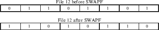
| SWAPF | The upper and lower nibbles (4 bits) of file F are swapped. | ||||||
| E.g. SWAPF 12,W The result is placed in W. | |||||||
| E.g. SWAPF 12 The result is placed in file 12. | |||||||
| |||||||
| TRIS | Load the TRIS register. | ||||||
| The contents of the W register are loaded into the TRIS register. | |||||||
| This then configures an I/O port as input or output. | |||||||
| |||||||
| This sets the 4 LSB's of port B as inputs and the 4 MSB's as outputs. N.B. 1 for an input, 0 for an output. | |||||||
| XORLW | The contents of the W register are Exclusive Ored with the literal. If the result is zero then the contents match. | ||||||
| i.e. If a number on the input port, indicating temperature, is the same as the literal then the result is zero and the zero bit is set. | |||||||
| i.e. 0 ⊕ 0 = 0, 0 ⊕ 1 = 1, 1 ⊕ 0 = 1, 1 ⊕ 1 = 0. | |||||||
| E.g. XORLW 67 | |||||||
| Status affected Z. | |||||||
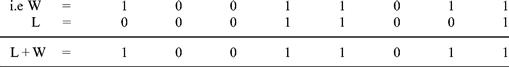
| XORWF | The contents of the W register are Exclusive Ored with the contents of the file F. i.e. If a number on the input port, indicating temperature, is the same as the W register then the result is zero and the zero bit is set. N.B. you can not Exclusive OR the input port directly with a file, you have to do this by loading the file into the W register with an MOVF instruction. | ||||||
| E.g. XORWF 17,W The result is placed in W. | |||||||
| E.g. XORWF 17 The result is placed in 17. | |||||||
| Status affected Z. | |||||||
Did you notice how vital the W register is in the operation of the microcontroller?
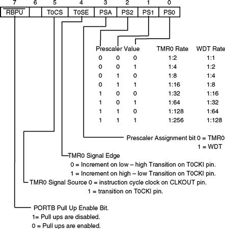
Figure 19.4 Option register
Data cannot go directly from A to B, it goes from A to W and then from W to B.