
13
EEPROM data memory
One of the special features of the 16F84, the 16F818 and some other micros is the EEPROM Data Memory. This is a section of Memory not in the usual program memory space. It is a block of data like the user files, but unlike the user files the data in the EEPROM Data Memory is saved when the microcontroller is switched off, i.e. it is non-volatile. Suppose we were counting cars in and out of a car park and we lost the power to our circuit. If we stored the count in EEPROM then we could load our count file with this data and continue without loss of data, when the power returns.
To access the data, i.e. read and write to the EEPROM memory locations, we must of course instruct the microcontroller. There are 64 bytes of EEPROM memory on the 16F84, 128 on the 16F818 and 256 on the 16F819. So we must tell the micro which address we require and if we are reading or writing to it.
When reading we identify the address from 0 to 3Fh (for the 16F84) using the address register EEADR. The data is then available in register EEDATA. When writing to the EEPROM data memory we specify the data in the register EEDATA and the location in the register EEADR.
Two other files are used to enable the process, they are EECON1 and EECON2, two EEPROM control registers.
Register EECON1 and EECON2 have addresses 8 and 9 respectively in Bank1.
The Register EECON1 is shown below in Figure 13.1.
![]()
Figure 13.1 The EECON1 register
| Bit 0, | RD is set to a 1 to perform a read. It is cleared by the micro when the read is finished. |
| Bit 1, | WR is set to a 1 to perform a write. It is cleared by the micro when the write is finished. |
| Bit 2, | WREN, WRite ENable a 1 allows the write cycle, a 0 prohibits it. |
| Bit 3, | WRERR reads a 1 if a write is not completed, reads a 0 if the write is completed successfully. |
| Bit 4, | EEIF interrupt flag for the EEDATA it is a 1 if the write operation is completed, it reads 0 if it is not completed or not started (for the 16F84). This bit has another purpose for the 16F818. We have not used this bit in this book. |
| Bit 7, | EEPGD, Program/Data EEPROM Select Bit. (Not used on 16F84.) This bit allows either the program memory or the data memory to be selected. 0 selects Data, 1 selects program memory. |
Example using the EEPROM
As usual, I think the best way of understanding how this memory works is to look at a simple example.
Suppose we wish to count events, people going into a building, cars going into a carpark etc. So if we loose the power to the circuit the data is still retained. The circuit for this is shown in Figure 13.2.

Figure 13.2 Switch press counting circuit
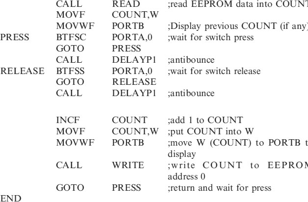
Switch 1 is used to simulate the counting process and the 8 LEDs on PORTB display the count in binary. (This is a good chance to practice counting in binary.) The switch of course needs de-bouncing.
Remember the idea of this circuit, we are counting events and displaying the count on PORTB. But if we loose power – when the power is re-applied we want to continue the count as if nothing had happened.
So when we switch on we must move the previous EEPROM Data into the COUNT file.
The flowchart is shown below in Figure 13.3.

Figure 13.3 The switch press count flowchart
Just a couple of points before we look at the program:
1. It is a good idea to make sure the EEPROM DATA MEMORY is reset at the very beginning. This can be done by writing 00h to EEPROM DATA address 00h when we blow the program into the chip – this is done with the following lines of code.
| ORG | 2100H |
| DE | 00H |
2100H is the address of the first EEPROM data memory file i.e. 00h.
DE is Define EEPROM data memory, so we are initializing it with 00h, and of course 2101H is EEPROM address1 etc.
Data can also be written into the EEPROM using MPLAB, with VIEW, EEPROM and writing the data in the EEPROM box as shown in Figure 13.4.
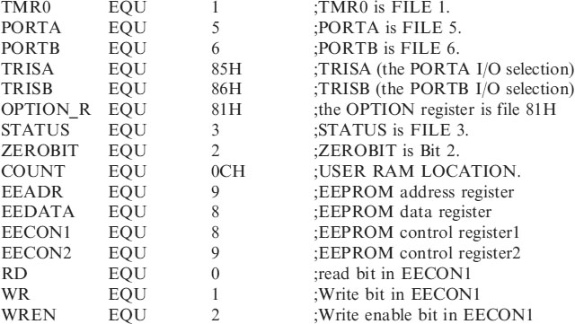
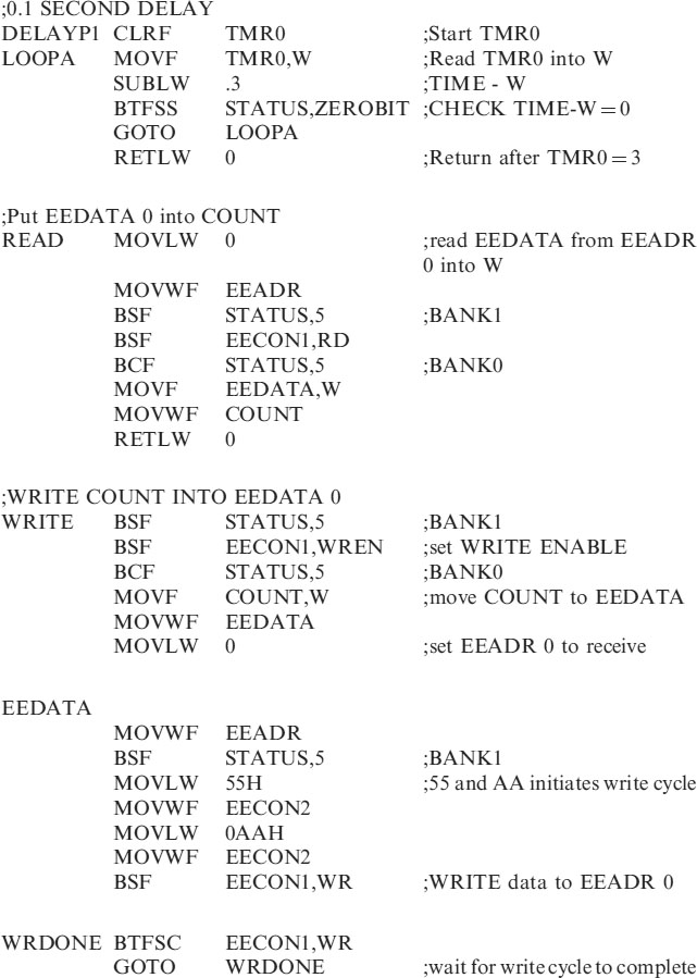
2. Reading and Writing to EEPROM data is not as straightforward as with user files, you probably suspected that! There is a block of code you need to use – just add it to your program as required.
When reading EEPROM data at address 0 to the file COUNT then CALL READ. The subroutine written in the header.
When writing the file COUNT to EEPROM data address 0, CALL WRITE.
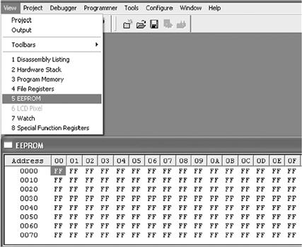
Figure 13.4 Writing EEPROM data
EEPROM program code
The complete program EEDATAWR.ASM is shown below:
| ;EEDATAWR.ASM | This program will count and display switch |
| ; | presses. |
| ; | The count is saved when the power is removed |
| ; | and continues when the |
| ; | power is re-applied. |
;**********************************************************
| LIST | P=16F84 | ;We are using the 16F84. |
| ORG | 2100H | ;ADDRESS EEADR 0 |
| DE | 00H | ;put 00H in EEADR 0 |
| ORG | 0 | ;0 is the start address. |
| GOTO | START | ;goto start! |
;**********************************************************
;Configuration Bits
| __CONFIG H′3FF0′ | ;selects LP oscillator, WDT off, PUT on, |
| ;Code Protection disabled. |
;*****************************************************

;**********************************************************

;**********************************************************
;Program starts now.
Microchip are continually expanding their range of microcontrollers and a new series of flash micros have been introduced, namely the 16F87X series which include 8k of program memory, 368 bytes of user RAM, 256 bytes of EEPROM data memory and an 8 channel 10 bit A/D converter. So now analogue measurements can be stored and saved in EEPROM Data!