
8
Program examples
New instructions used in this chapter:
Counting events
Counting of course is a useful feature for any control circuit. We may wish to count the number of times a door has opened or closed, or count a number of pulses from a rotating disc. If we count cars into a car park we would increment a file count every time a car entered, using the instruction INCF COUNT. If we needed to know how many cars were in the car park we would have course have to reduce the count by one every time a car left. We would do this by DECF COUNT. To clear the user file COUNT to start we would CLRF COUNT. In this way the file count would store the number of cars in the car park. If you prefer COUNT could be called CARS. It is a user file call it what you like.
Let's look at an application.
Design a circuit that will count 10 presses of a switch, then turn an LED on and reset when the next ten presses are started. The hardware is that of Figure 5.1 with A0 as the switch input and B0 as the output to the LED.
There are two ways to count, UP and DOWN. We usually count up and know automatically when we have reached 10. A computer however knows when it reaches a count of 10 by subtracting the count from 10. If the answer is zero, then bingo. A simpler way however is to start at 10 and count down to zero – after 10 events we will have reached zero without doing a subtraction. Zero for the microcontroller is a really useful number.
The initial flowchart for this problem is shown in Figure 8.1.

Figure 8.1 Initial counting flowchart
To ensure that the LED is OFF after the switch is pressed for the eleventh time put in TURN OFF LED after the switch is pressed, as shown in Figure 8.2.
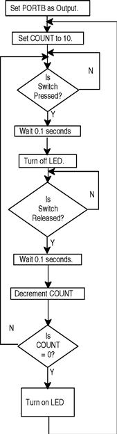
Figure 8.2 Final counting flowchart
N.B. The switch will bounce and the micro is fast enough to count these bounces, thinking that the switch has been pressed several times. A 0.1 second delay is inserted after each switch operation to allow time for the bounces to stop.
The final flowchart is shown in Figure 8.2.
The program for the counting circuit
;COUNT84.ASM using the 16F84 with a 32kHz. crystal
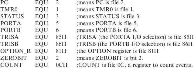
;EQUATES SECTION
![]()

;*********************************************************
| LIST | P = 16F84 | ;we are using the 16F84. |
| ORG | 0 | ;the start address in memory is 0 |
| GOTO | START | ;goto start! |
;*********************************************************
| __CONFIG H′3FF0′ | ;selects LP oscillator, WDT off, PUT on, |
| ;Code Protection disabled. |
;*********************************************************
;SUBROUTINE SECTION.
;*********************************************************
;CONFIGURATION SECTION

;*********************************************************

How does it work?
• The file COUNT is first loaded with the count i.e. 10 with:
| MOVLW | .10 | |
| MOVWF | COUNT | ;Put 10 into COUNT. |
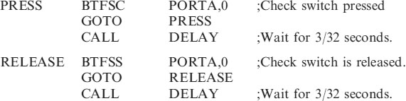
• We then wait for the switch to be pressed, by PORTA,0 going low:
![]()
| CALL | DELAY | ;Wait for 3/32 seconds. |
| BCF | PORTB,0 |
• Wait for switch to be released
![]()
| CALL | DELAY | ;Wait for 3/32 seconds. |
• Decrement the file COUNT, if zero turn on LED and return to begin. If not zero continue pressing the switch.
| DECFSZ | COUNT | ;Dec COUNT skip if 0. |
| GOTO | PRESS | ;Wait for another press. |
| BSF | PORTB,0 | ;Turn on LED. |
| GOTO | BEGIN | ;Restart |
This may appear to be a lot of programming to count presses of a switch, but once saved as a subroutine it can be reused in any other programs.
Look up table
A look up table is used to change data from one form to another i.e. pounds to kilograms, °C to °F, inches to centimeters etc. The explanation of the operation of a look up table is best understood by way of an example.
7-Segment display
Design a circuit that will count and display on a 7-segment display, the number of times a button is pressed, up to 10. The circuit diagram for this is shown in Figure 8.3.

Figure 8.3 Circuit diagram of the 7-segment display driver
The flowchart for the 7-Segment Display Driver is shown in Figure 8.4.
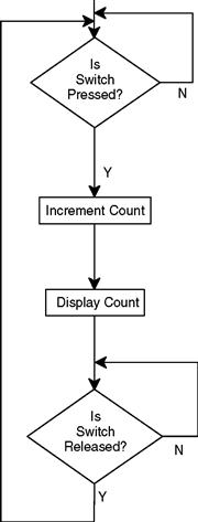
Figure 8.4 Initial flowchart for the 7-segment driver
This is a basic solution that has a few omissions:
• The switch bounces when pressed.
• Clear the count at the start.
• The micro counts in binary, we require a 7-segment decimal display. So we need to convert the binary count to drive the relevant segments on the display.
The amended flowchart is shown in Figure 8.5.

Figure 8.5 Amended flowchart for 7-segment display
The flowchart is missing just one thing! What happens when the count reaches 10 The counter needs resetting (it would count up to 255 before resetting). The final flowchart is shown in Figure 8.6.

Figure 8.6 Final flowchart for 7-segment display
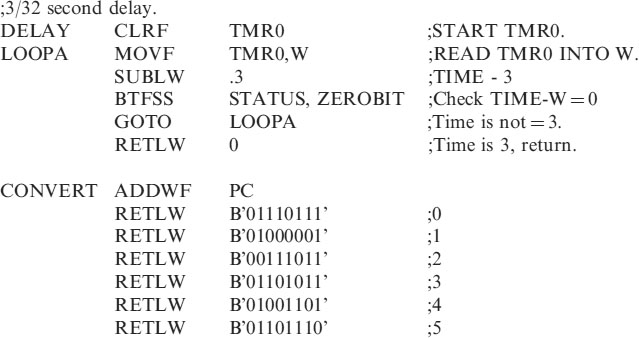
Now about this look up table:
Table 8.1 shows the configuration of PORTB to drive the 7-segment display. (Refer also to Figure 8.3).
Table 8.1 Binary code to drive 7-segment display

The look up table for this is:

How does the look up table work?
Suppose we need to display a 0.
We move 0 into W and CALL the look up table, here it is called CONVERT.
The first line says ADD W to the Program Count, since W = 0 then go to the next line of the program which will return with the 7-segment value 0.
Suppose we need to display a 6.
Move 6 into W and CALL CONVERT. The first line says ADD W to the Program Count, since W contains 6 then go to the next line of the program and move down 6 more lines and return with the code for 6, etc.
Just one more thing: To check that a count has reached 10, subtract 10 from the count if the answer is 0, bingo!
The program listing for the complete program is:
;EQUATES SECTION
;********************************************************
| LIST | P = 16F84 | ;we are using the 16F84. |
| ORG | 0 | ;the start address in memory is 0 |
| GOTO | START | ;goto start! |
;*********************************************************
;Configuration Bits
| __CONFIG H′3FF0′ | ;selects LP oscillator, WDT off, PUT on, |
| ;Code Protection disabled. |
;*********************************************************
;SUBROUTINE SECTION.

;*********************************************************

;*********************************************************
;Program starts now.

How does the program work?
• The file count is cleared (to zero) and we wait for the switch to be pressed.

• Wait for 0.1 seconds, Anti-bounce.
| CALL | DELAY |
• Add 1 to COUNT and check to see if it 10:
| INCF | COUNT | ;Add 1 to COUNT. |
| MOVF | COUNT,W | ;Move COUNT to W. |
| SUBLW | .10 | ;COUNT-10, W is altered. |
| BTFSC | STATUS, ZEROBIT | ;Is COUNT - 10 = 0? |
• If COUNT is 10, Clear it to 0 and output the count as 0. If the COUNT is not 10 then output the count.
| CLRF | COUNT | ;Count = 10 Make Count = 0 |
| MOVF | COUNT,W | ;Put Count in W again. |
| CALL | CONVERT | ;Count is not 10, carry on. |
| MOVWF | PORTB | ;Output number to display. |
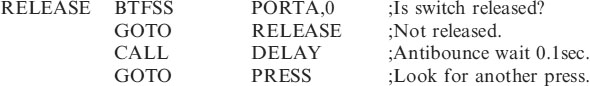
• Wait for the switch to be released and de-bounce. Then return to monitor the presses.
Test your understanding
A look up table to change °C to °F is shown below, called DEGREE
DEGREE ADDWF PC; ADD W to Program Count.


Another application of the use of the look up table is a solution for a previous example i.e. the “Control Application – A Hot Air Blower.” Introduced in Chapter 5.
In this example when PORTA was read the data was treated as a binary number, but we could just as easily treat the data as decimal number.
| i.e. A2 A1 A0 | = 000 or 0 |
| = 001 or 1 | |
| = 010 or 2 | |
| = 011 or 3 | |
| = 100 or 4 | |
| = 101 or 5 | |
| = 110 or 6 | |
| = 111 or 7 |
The look up table for this would be:

The complete program listing for the program DISPLAY2 would be:
;DISPLAY2.ASM
;EQUATES SECTION

;*********************************************************
| LIST | P = 16F84 | ;we are using the 16F84. |
| ORG | 0 | ;the start address in memory is 0 |
| GOTO | START | ;goto start! |
;**********************************************************
;Configuration Bits
| __CONFIG H′3FF0′ | ;selects LP oscillator, WDT off, PUT on, |
| ;Code Protection disabled. |
;*****************************************************

;******************************************************
;CONFIGURATION SECTION

;*********************************************************
;Program starts now.

How does the program work?
• The program first of all reads the value of PORTA into the working register, W:
| MOVF | PORTA,W |
• The CONVERT routine is called which returns with the correct setting of the outputs in W. i.e. If the value of PORTA was 3 then the look up table would return with 00000001 in W to turn on B0 and turn off B1:
| CALL | CONVERT | ;Obtain O/Ps from I/Ps. |
| MOVWF | PORTB | ;switch on O/Ps |
• The program then returns to check the setting of PORTA again.
Numbers larger than 255
The PIC Microcontrollers are 8 bit devices, this means that they can easily count up to 255 using one memory location. But to count higher then more than one memory location has to be used for the count.
Consider counting a switch press up to 1000 and then turn on an LED to show this count has been achieved. The circuit for this is shown in Figure 8.7.

Figure 8.7 Circuit for 1000 count
To count up to 1000 in decimal i.e. 03E8 in hex, files COUNTB and COUNTA will store the count (a count of 65535 is then possible).
COUNTB will count up to 03H then when COUNTA has reached E8H, LED1 will light indicating the count of 1000 has been reached.
The flowchart for this 1000 count is shown in Figure 8.8.
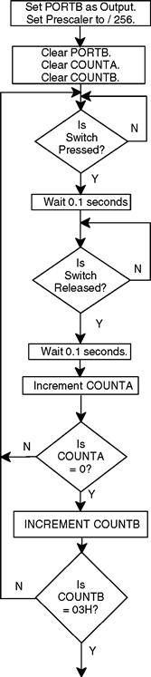

Figure 8.8 Count of 1000 flowchart
Flowchart explanation
• The program is waiting for SW1 to be pressed. When it is, there is a delay of 0.1 seconds to allow the switch bounce to stop.
• The program then looks for the switch to be released and waits 0.1 seconds for the bounce to stop.
• 1 is then added to COUNTA and a check is made to see if the count has overflowed i.e. reached 256. (255 is the maximum it will hold, when it reaches 256 it will reset to zero just like a two digit counter would reset to zero going from 99 to 100.)
• If COUNTA has overflowed then we increment COUNTB.
• A check is made to see if COUNTB has reached 03H, if not we return to keep counting.
• If COUNTB has reached 03H then we count presses until COUNTA reaches E8H. The count in decimal is then 1000 and the LED is lit.
Any count can be attained by altering the values COUNTB and COUNTA are allowed to count up to i.e. to count up to 5000 in decimal which is 1388H. Ask if COUNTB = 13H then count until COUNTA has reached 88H.
The program listing
;CNT1000.ASM
;EQUATES SECTION

;*********************************************************
| LIST | P = 16F84 | ;we are using the 16F84. |
| ORG | 0 | ;the start address in memory is 0 |
| GOTO | START | ;goto start! |
;*********************************************************
;Configuration Bits
| __CONFIG H′3FF0′ | ;selects LP oscillator, WDT off, PUT on, |
| ;Code Protection disabled. |
;*****************************************************

;*********************************************************
;CONFIGURATION SECTION

;*********************************************************
;Program starts now.


How does the program work?
• The two files used for counting are cleared.
| CLRF | COUNTA |
| CLRF | COUNTB |
• As we have done previously we wait for the switch to be pressed and released and to stop bouncing:
• We add1 to file COUNTA and check to see if it zero. If it isn't then continue monitoring presses. (The file would be zero when we add 1 to the 8 bit number 1111 1111, it overflows to 0000 0000):
| INCFSZ | COUNTA | ;Inc. COUNT skip if 0. |
| GOTO | PRESS |
• If the file COUNTA has overflowed then we add 1 to the file COUNTB, just like you would do with two columns of numbers. We then need to know if COUNTB has reached 03H. If COUNTB is not 03H then we return to PRESS and continue monitoring the presses.
| INCF | COUNTB | |
| MOVLW | 03H | ;Put 03H in W. |
| SUBWF | COUNTB,W | ;COUNTB - W (i.e. 03) |
| BTFSS | STATUS, ZEROBIT | ;IS COUNTB = 03H? |
| GOTO | PRESS | ;No |
• Once COUNTB has reached 03H we need only wait until COUNTA reaches 0E8H and we would have counted up to 03E8H i.e. 5000 in decimal. Then we turn on the LED.

This listing can be used as a subroutine in your program to count up to any number to 65535 (or more if you use a COUNTC file). Just alter COUNTB and COUNTA values to whatever values you wish, in the two places marked * in the program.
Question. How would you count up to 20,000?
Answer. (Have you tried it first!!).
20,000 = 4E20H so COUNTB would count up to 4EH and COUNTA would then count to 20H.
Question. How would you count to 100,000?
Answer. 100,000 = 0186A0H, you would use a third file COUNTC to count to 01H, COUNTB would count to 86H and COUNTA would count to A0H.
Programming can be made a lot simpler by keeping a library of subroutines. Here is another … .
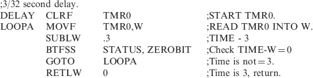
Long time intervals
Probably the more frequent use of a large count is to count TMR0 pulses to generate long time intervals. We have previously seen in the section on delay that we can slow the internal timer clock down to 1/32 seconds. Counting a maximum of 255 of these gives a time of 255 × 1/32 = 8 seconds. Suppose we want to turn on an LED for 5 minutes when a switch is pressed.
5 minutes = 300 seconds = 300 × 32 (1/32 seconds) i.e. a TMR0 count of 9600. This is 2580 in hex. The circuit is the same as Figure 8.7 for the 1000-count circuit, and the flowchart is shown in Figure 8.9.
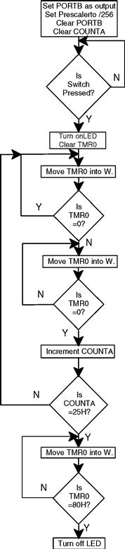
Figure 8.9 Flowchart for the 5 minute delay
Explanation of the flowchart
1. Wait until the switch is pressed, the LED is then turned on.
2. TMR0 is cleared to start the timing interval.
3. TMR0 is moved into W (read) to catch the first count.
4. Then wait for TMR0 to return to zero, (the count will be 256) i.e. 100 in hex.
5. COUNTA is then incremented and steps 3 and 4 repeated until COUNTA reaches 25H.
6. Wait until TMR0 has reached 80H.
7. The count has reached 2580H i.e. 9600 in decimal. 5 minutes has elapsed and the LED is turned off.
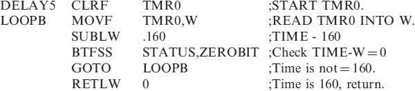
Program listing for 5 minute delay
;EQUATES SECTION

;*********************************************************
| LIST | P = 16F84 | ;we are using the 16F84. |
| ORG | 0 | ;the start address in memory is 0 |
| GOTO | START | ;goto start! |
;*********************************************************
;Configuration Bits
| __CONFIG H′3FF0′ | ;selects LP oscillator, WDT off, PUT on, |
| ;Code Protection disabled. |
;********************************************************
;CONFIGURATION SECTION

;*********************************************************
;Program starts now.
![]()

The explanation of this program operation is similar to that of the count to 1000, done earlier in this chapter.
This listing can be used as a subroutine and times upto 65535 × 1/32 seconds i.e. 34 minutes can be obtained.
Problem: Change the listing to produce a 30 minute delay.
Hint. 1800sec in hex is 0708H.
One hour delay
Another and probably a simpler way of obtaining a delay of say 1 hour, is
• CALL it 6 times, this gives a delay of 30 seconds,
• put this in a loop to repeat 120 times, i.e.120 × 30 seconds = 1 hour.
This code for the 1 hour subroutine will look like:-


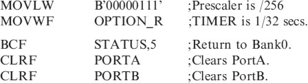
The program for the one-hour delay
| ;ONEHOUR.ASM for 16F84. | This sets PORTA as an INPUT (NB 1 |
| ; | means input) and PORTB as an OUTPUT |
| ; | (NB 0 means output). The OPTION |
| ; | register is set to /256 to give timing pulses |
| ; | of 1/32 of a second. |
| ; | 1hour and 5 second delays are |
| ; | included in the subroutine section. |
;*********************************************************
;EQUATES SECTION

;*********************************************************
| LIST | P = 16F84 | ;we are using the 16F84. |
| ORG | 0 | ;the start address in memory is 0 |
| GOTO | START | ;goto start! |
;**********************************************************
;Configuration Bits
| __CONFIG H′3FF0′ | ;selects LP oscillator, WDT off, PUT on, |
| ;Code Protection disabled. |
;*****************************************************
;SUBROUTINE SECTION.
![]()

;*********************************************************
;*********************************************************
