
3
Introductory projects
New instructions used in this chapter:
Let's have a look at a few variations of flashing the LEDs on and off to develop our programming skills.
LED_Flasher2
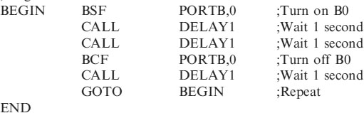
Suppose we want to switch the LED on for 2 seconds and off for 1 second. Figure 2.1 shows the circuit diagram for this application. The code for this would be:
;Program starts now.
NB. This code would be added to HEADER84.ASM into the section called, “Program starts now”.
To do this open MPLAB, then FILE – OPEN – HEADER84.ASM
Add the code and saveas LED_FLASHER2.ASM
The text would then be assembled by the MPLAB software and then blown into the Microcontroller as explained in Chapter 2.
How does it work?
The comments alongside the code explain what the lines are doing. Because we do not have a 2 second delay we wait for 1 second twice. You can of course write a 2 second delay routine but we will be looking at this later.
SOS
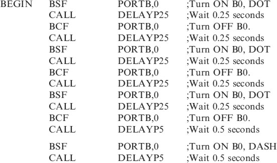
For our next example let us switch B0 on and off just as we have been doing but this time we will use delays of ¼ second and ½ second. This is not much different than we have done previously, but instead of turning an LED on and off we will replace it by a buzzer. The program is not just going to turn a buzzer on and off, but do it in a way that generates the signal, SOS. Which is DOT,DOT,DOT DASH,DASH,DASH DOT,DOT, DOT. Where the DOT is the buzzer on for ¼ second and the DASH is the buzzer on for ½ second with ¼ second between the beeps.
The circuit diagram for the SOS circuit is shown in Figure 3.1.
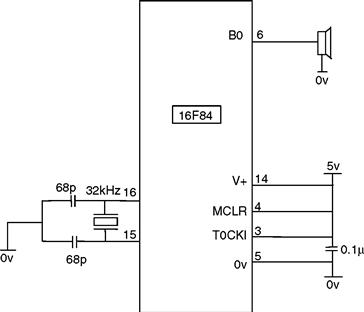
Figure 3.1 SOS circuit diagram
Code for SOS circuit
The complete code for the SOS circuit is shown below because an extra subroutine, DELAYP25, has been added.
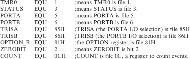
;SOS.ASM for 16F84. This sets PORTA as an INPUT (NB 1means input)
;and PORTB as an OUTPUT (NB 0 means output).
;The OPTION Register is set to /256 to give timing pulses of 1/32 of a second.
;1second, 0.5 second and 0.25 second delays are included in the subroutine
;section.
;*********************************************************
;EQUATES SECTION
;*********************************************************
| LIST | P = 16F84 | ;we are using the 16F84. |
| ORG | 0 | ;the start address in memory is 0 |
| GOTO | START | ;goto start! |
;******************************************************************
;Configuration Bits
| __CONFIG H’3FF0’ | ;selects LP oscillator, WDT off, PUT on, |
| ;Code Protection disabled. |
;*****************************************************
;SUBROUTINE SECTION


;*********************************************************
;*********************************************************
;Program starts now.
How does it work?
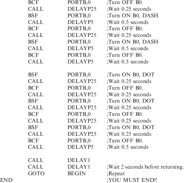
I think the explanation of the code is clear from the comments. At the end of the SOS the program has a delay of 2 seconds before repeating. This should be a useful addition to any alarm project.
We will now move onto switching a number of outputs on and off. Consider flashing all 8 outputs on PORTB on and off at ½ second intervals.
Flashing 8 LEDs
The circuit for this is shown in Figure 3.2.
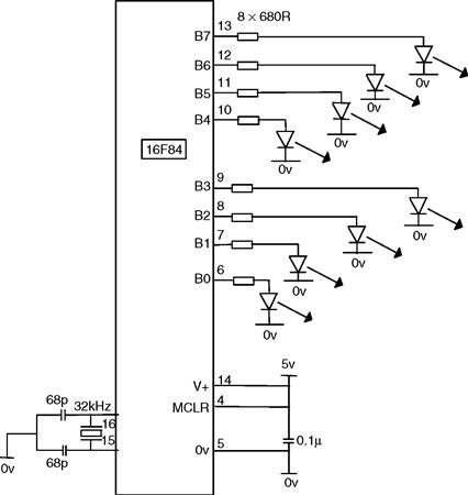
Figure 3.2 Flashing 8 LEDs
This code is to be added to HEADER84.ASM as in LED_FLASHER2.ASM
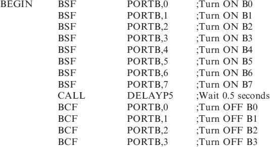
Save the program as FLASH8.ASM, assemble and program the 16F84 as indicated in Chapter 2.
There is an easier way than this of switching all outputs on a port, which we look at later in this chapter with a set of disco lights.
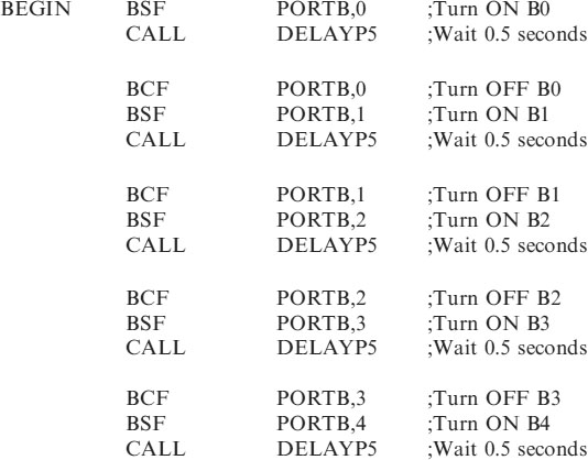
Chasing 8 LEDs
Let's now consider the code to chase the 8 LEDs. The circuit of Figure 3.2 is required for this. The code will switch B0 on and off, then B1, then B2 etc.
;Program starts now.
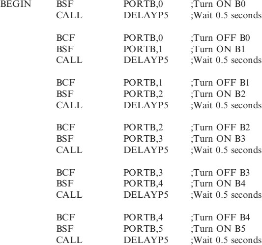
This code once again is added to the bottom of HEADER84.ASM and is saved as
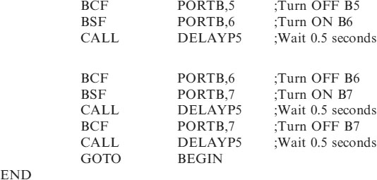
Now that we have chased the LEDs one way let's run them back the other way and call the program CHASE8B.ASM. I think you know the routine add the code to the bottom of HEADER84.ASM etc. So I will not mention it again.
;Program starts now.
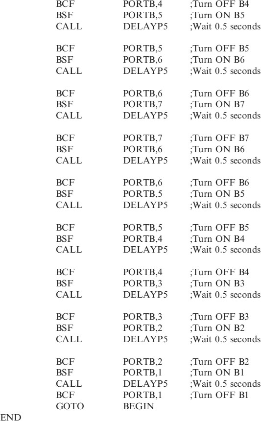
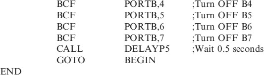
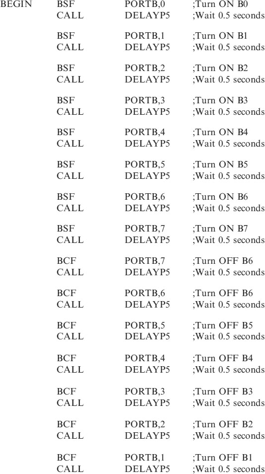
Just one last flasher program. Let us switch each output on in turn leaving them on as we go and then switch them off in turn. Try this for yourselves before looking at the solution!
The program is saved as UPANDDOWN.ASM
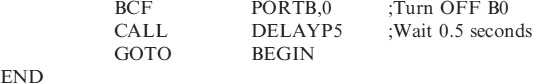
There are lots of other combinations for you to practice on. I'll leave you to experiment further.
Consider another example of the delay routine:
Traffic lights
If you have ever tried to design a ‘simple’ set of traffic lights then you will appreciate how much circuitry is required. An oscillator circuit, counters and logic decode circuitry.
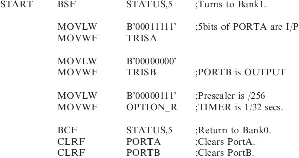
The microcontroller circuit is a much better solution even for this ‘simple’ arrangement. The circuit is shown in Figure 3.3.
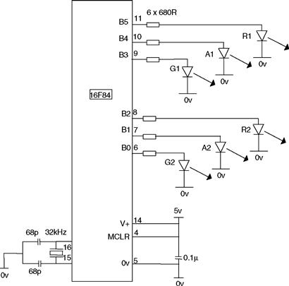
Figure 3.3 Traffic lights circuit
A truth table of the operation of the lights is probably a better aid to a solution rather than a flowchart.
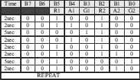
Program listing for the traffic lights
;*********************************************************
;Program starts now.
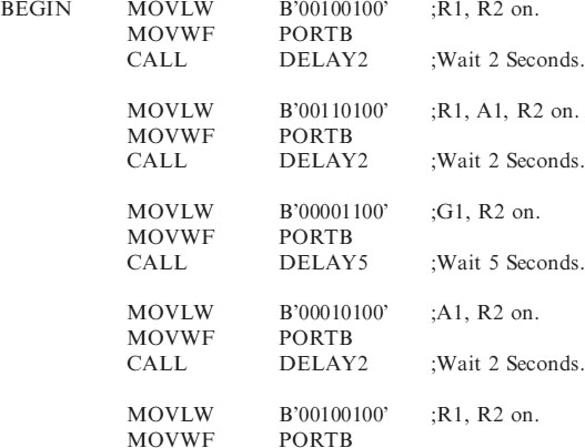
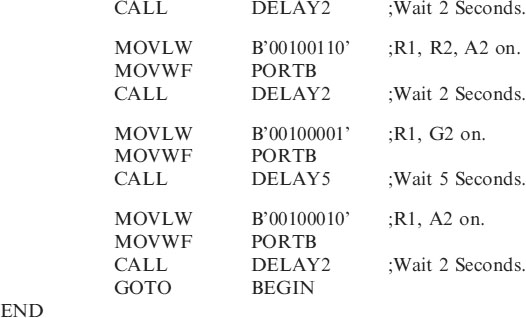
How does it work
In a previous examples we turned LEDs on and off with the two commands BSF and BCF, but a much better way has been used with the TRAFFIC.ASM program.
The basic difference is the introduction of two more commands:
The data, in this example, binary numbers, are moved to W and then to the file which is the output PORTB to switch the LEDs on and off. Unfortunately the data cannot be placed in PORTB with only one instruction it has to go via the W register.
So:
| MOVLW | B’00100100’ | clears B7, B6, sets B5, clears B4, B3, sets B2 and clears B1, B0 in the W register |
| MOVWF | PORTB | moves the data from the W register to PORTB to turn the relevant LEDs on and off. |
All 8 outputs are turned on/off with these 2 instructions.
CALL DELAY2 and CALL DELAY5 waits 2 seconds and 5 seconds before continuing with the next operation. DELAY2 and DELAY5 need adding to the subroutine section as:
![]()

The W register
The W or working register is the most important register in the micro. It is in the W register were all the calculations and logical manipulations such as addition, subtraction, and-ing, or-ing etc., are done.
The W register shunts data around like a telephone exchange re-routes tele phone calls. In order to move data from locationA to locationB, the data has to be moved from locationA to W and then from W to location B
NB. If the three lines in the TRAFFIC.ASM program are repeated then any pattern and any delay can be used to sequence the lights – you can make your own disco lights!
Repetition (e.g. disco lights)
Instead of just repeating one sequence over and over, suppose we wish to repeat several sequences before returning to the start as with a set of disco lights.
Consider the circuit shown in Figure 3.4. The 8 ‘Disco Lights’ B0-B7 are to be run as two sequences.
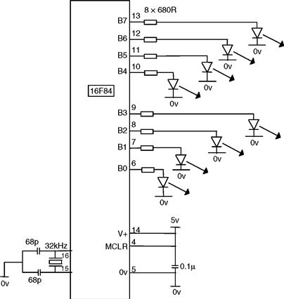
Figure 3.4 Disco lights
| Sequence 1 | Turn all lights on. |
| Wait. | |
| Turn all lights off | |
| Wait | |
| Sequence 2 | Turn B7-B4 ON, B3-B0 OFF |
| Wait | |
| Turn B7-B4 OFF, B3-B0 ON | |
| Wait |
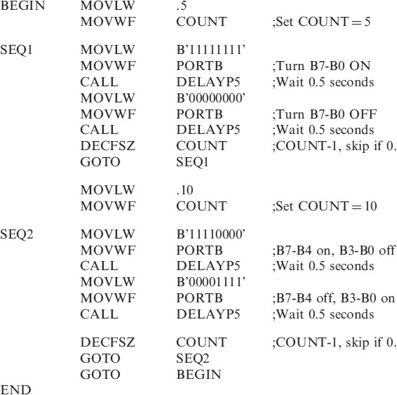
Suppose we wish Sequence 1 to run 5 times before going onto Sequence 2 to run 10 times and then repeat. A section of program is repeated a number of times with 4 lines of code shown below:
| MOVLW | .5 | ;Move 5 into W |
| MOVWF | COUNT | ;Move W into user file COUNT |
| . | ||
| SEQ1 | ||
| . | ||
| DECFSZ | COUNT | ;decrement file COUNT skip if zero. |
| GOTO | SEQ1 | ;COUNT not yet zero, repeat sequence |
• The first two lines set up a file COUNT with 5. (Count is the first user file and is found in memory location 0CH.) 5 is first of all moved into W then from there to file COUNT.
• The DECFSZ COUNT instruction, DECrement File and Skip if Zero, decrements, takes 1 off, the file COUNT and skips GOTO SEQ1 if the count is zero, if not zero then do SEQ1 again.
This way SEQ1 is executed 5 times and COUNT goes from 5 to 4 to 3 to 2 to 1 to 0 when we skip and follow onto SEQ2. SEQ2 is then done 10 times, say, and the code would be:
| MOVLW | .10 | ;Move 10 into W |
| MOVWF | COUNT | ;Move W into user file COUNT |
| . | ||
| SEQ2 | ||
| . | ||
| DECFSZ | COUNT | ;decrement file COUNT skip if zero. |
| GOTO | SEQ2 | ;COUNT not yet zero, repeat sequence |
Program code for the disco lights
;*********************************************************
;Program starts now.
Using the idea of repeating sequences like this any number of combinations can be repeated. The times of course do not need to be of 0.5 seconds duration. The flash rate can be speeded up or slowed down depending on the combination.
Try programming a set of your own Disco Lights. This should keep you quiet for hours (days!).
More than 8 outputs
Suppose we wish to have a set of disco lights in a 3 × 3 matrix as shown in Figure 3.5. This configuration of course requires 9 outputs. We have 8 outputs on PORTB so we need to make one of the PORTA bits an output also, say PORTA bit0.
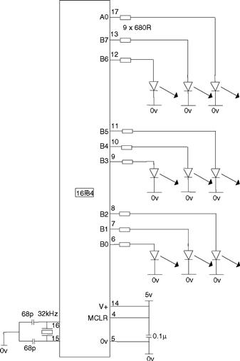
Figure 3.5 9 Disco light set
To change PORTA bit0 from an input to an output change the lines in the Configuration section from:
| MOVLW | B’00011111’ |
| MOVWF | TRISA |
| to | |
| MOVLW | B’00011110’ |
| MOVWF | TRISA |
NB a 1 signifies an input a 0 signifies an output.
So to set a ‘+’ pattern in the lights we turn on B7, B4, B1, B3 and B5, keeping the others off. The code for this would be:
| MOVLW | B’00000000’ | |
| MOVWF | PORTA | ;A0 is clear |
| MOVLW | B’10111010’ | |
| MOVWF | PORTB | ;B7, B5, B4, B3 and B1 are on |
So to set an ‘X’ pattern in the lights we turn on B6, B4, B2, A0 and B0, keeping the others off. The code for this would be:
| MOVLW | B’00000001’ | |
| MOVWF | PORTA | ;A0 is on |
| MOVLW | B’01010101’ | |
| MOVWF | PORTB | ;B6, B4, B2 and B0 are on |
There are endless combinations you can make with 9 lights. In fact there are 512. That is 29. This should give you something to go at!