
Chapter 5. Relational Database Design
In this chapter
Working with Entities and Attributes
Understanding the Role of Keys in Database Design
Many-to-Many Relationships: Solving the Puzzle
Normalizing Data: What Goes Where
The Basics of Process Analysis
FileMaker Extra: Complex Many-to-Many Relationships
Understanding Database Design
By now you’ve designed a simple FileMaker database and built some nice data-entry screens and some reports. Your friends and co-workers are clamoring for you to add features. Can your system do invoicing? Inventory tracking? Bar-coding?
Well, it can probably do all those things. But it’s going to take some planning. If this is your first time out with FileMaker, you’re like the home carpenter who’s just built her first birdhouse. It’s a nice birdhouse, but your kids want a tree fort. That’s not just going to take more work; it’s going to take more thought as well.
FileMaker is a tool for building database applications. Both parts of that term are important. By applications, we mean coherent pieces of software with which users can interact in defined and predictable ways. And by databases, of course, we mean databases, pointing to the fact that FileMaker applications are, in the end, designed to help generate, store, and retrieve data.
Much of the rest of this book concentrates on either the application angle or the database angle. In this chapter, we’re going to lay out for you the fundamentals of database design. When you’re designing a simple contact manager or recipe book, the database structure is pretty clear. You know what fields you need to track and what kinds of fields they are. But when you get into tracking additional categories of data in the same database, things get trickier. If you want to build bigger and better databases, you’ll need a firm grounding in database analysis and database design. Don’t worry if that sounds ominous. It’s easier than it appears.
Database Analysis
One of the great beauties of FileMaker is that it’s very easy to just jump right in and start building things that work. And this is fine, as long as you can keep the whole plan in your head.
Earlier chapters have looked at some practical techniques for separating and organizing data in a FileMaker database system. This chapter takes that work another step. Here you’ll learn some tools for analyzing database problems and translating them into buildable designs.
This chapter approaches things and their relationships somewhat abstractly. Your goal here won’t be a finished FileMaker system, but rather a more general design document. You’ll learn a simple but powerful design process to help you take a real-world problem description and translate it into a blueprint that a database designer could use to build the database in a real-world database development system. This design document is an entity-relationship diagram (ERD). The process for creating an entity-relationship diagram, somewhat simplified, looks like this:
- Identify all the types of things involved in the problem being modeled (customers and sales, for example, or trucks, drivers, and routes).
- For each type of thing, identify its attributes (customers have first and last names, truck routes have a beginning and an end).
- Looking across all the types of things, determine the fundamental relationships between them (truck drivers have routes, trucks have drivers).
- Draw up your findings into an entity-relationship diagram.
The ERD, again, is an abstract document that you can implement (build) with FileMaker or some other database tool. The sections that follow examine each of the steps of this process in much more detail.
Working with Entities and Attributes
When you set out to design a database system, there are two concepts you simply must be familiar with before you can say you have a solid planning foundation. You need to know the types of things your system will track, and you need to know the characteristics of each of those things. In a recipe list, for example, you track one kind of thing: recipes. A recipe’s characteristics are, for example, recipe name, recipe type, calories, ingredients, and cooking time. You could draw it out like this:
Recipe
- Name
- Type
- Ingredients
- Cooking Time
- Calories
- Directions
Here is one thing followed by a collection of its characteristics. A bigger database system might store information about several kinds of things, each with its own set of characteristics. For example, if I want to write a database system for a motorcycle company, I might want to track information about motorcycles, customers, and sales. Now I have three kinds of things, each with its own set of characteristics.
In database design terminology, the things in your database system are entities. Each entity is a specific, distinct kind of thing, about which you need to track information. This system tracks data about three distinct kinds of things. And each kind of thing has certain characteristics, which in the technical jargon are attributes. The motorcycle example includes three entities, and each has some specific number of attributes (see Table 5.1).
Table 5.1. Simple Analysis of a Database Structure
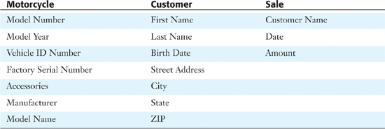
The first indispensable step in solid database design is to determine what entities (things) your proposed system needs to track, and what the attributes (characteristics) of each entity are. It’s not just the first step, though—it’s also the third, fifth, seventh, and so forth. Your list of things and their characteristics will inevitably change during your analysis, sometimes quite frequently. This is not a bad thing. It’s a natural part of database design. You’ll inevitably revisit and refine your list of entities and their attributes several times in the course of designing the system.
Roughly speaking, an entity is a class of things that all look more or less alike. In other words, from a database standpoint, you track many instances of an entity, and you track the same kind of information about each one. In a banking system, you’d probably have an entity called Customer because a banking database wants to keep track of many different customers, and wants to record roughly the same kinds of data about each one. You’ll always want to know a customer’s birth date, Social Security number, home address, and the like.
Attributes, on the other hand, refer to the kinds of information you track about each entity. If Customer is an entity in our banking database, birth date, home address, and Social Security number are among the attributes of a customer.
It won’t surprise you to learn that entities often correspond to actual database tables, and attributes often correspond to database fields. More likely than not, a banking database will have a Customer table with fields for date of birth, address, and Social Security number.
The entities in these diagrams are purely abstract things. They might or might not translate directly into database tables or even physical objects. Your FileMaker solution might (and almost certainly will) end up with tables not represented on your design diagram.
It’s fairly easy to represent entities and attributes in the graphical notation of an ERD. Sometimes it’s more convenient to draw an entity without showing any of its attributes, in which case you can draw it in a simple box, as shown in Figure 5.1.
Figure 5.1. A simple preliminary ERD showing entities for customers and accounts, with no attributes shown.
![]()
Sometimes it’s appropriate to show entities with some or all of their attributes, in which case you can add the attributes as shown in Figure 5.2.
Figure 5.2. An ERD showing entities for customers and accounts, with attributes shown.
All design processes are iterative. As you move along, constantly check your logic; it is easy to enthusiastically wander down a garden path into a swamp. For example, in the database structure described here, look to see whether you made any invalid assumptions. Not every assumption is wrong, but you should know if you are in any way limiting or distorting the data.
For example, the attributes of customers include a birth date. That means that a customer can be only a single person with a single birth date. Is that a reasonable assumption? It might be. Perhaps there is a terminology tweak: If your customer is a company, the birth date field might be the date of incorporation or registration of the company. You would then change the name of the field so that both circumstances are covered. Depending on the purpose to which the field is to be used, it might be that in the case of two people joining together to buy a motorcycle, the birth date might be that of the younger (or older).
Or, after realizing that the inclusion of that field raises questions, you might go back to the user (or to yourself if you are the user) and ask why that field is included. Sometimes the review and questioning process clarifies the data structure by simplifying it and removing unneeded data.
Entities Versus Attributes: A Case Study
The focus of this chapter is in taking descriptions of real-world problems and turning them into usable ERDs. As was noted earlier, your first step in trying to model a problem into an ERD is sorting out the entities from the attributes. To see how to tackle this, let’s begin with an example of a simple process description.
Now you know the basics of Maurizio’s business. Next you need to develop a list of potential entities. Here are some possibilities:
Fish
Storefront
Sale
Consumer
Load of fish
Variety
Quantity
Cost
Purchase
Vendor
Volume discount
Usually the rule of thumb to apply when coming up with a list of possible entities is to pull out every word that’s a noun; in other words, every word that represents a specific thing.
These are typically referred to as candidate entities in that they all represent possible entities in the system. But are they all entities? You can immediately cross Storefront, Sale, and Consumer off the list, for the simple reason that the process description already says that these are parts of his business that Maurizio doesn’t want to automate at this time. That leaves us with the following potential entities:
Fish
Load of fish
Variety
Quantity
Cost
Purchase
Vendor
Volume discount
Well, Fish and Load of Fish look like they refer to the same thing. According to the process description, a load of fish is actually a quantity of fish that Maurizio bought to resell. Put in those terms, it’s clearly the same thing as a purchase. Now the list looks like this:
Purchase (of fish)
Variety
Quantity
Cost
Vendor
Volume discount
These all seem like reasonable things to track in a database system. But are they all entities? Remember that an entity is a kind of thing. The thing will probably appear many times in a database, and the system will always track a coherent set of information about the thing. Put that way, a purchase of fish sounds like an entity. You’ll record information about many fish purchases in Maurizio’s database.
What about something like cost? The Cost in the process description refers to the price Maurizio paid for a load of fish, so cost isn’t really an entity. It’s the price paid for one load of fish. It’s actually a piece of information about a fish purchase because each fish purchase has an associated cost. The same is also true for Variety and Quantity. These are all attributes of the Purchase entity.
Then you get to Vendor. A vendor is clearly a category of thing; you’ll probably want to store information about many vendors in this database, so you can consider a vendor to be an entity. This leaves Volume Discount. Well, that one’s a bit tricky. It probably applies to a vendor, and might reasonably be called an attribute of a vendor. If you assume that each vendor can offer a discount of some kind, it makes sense for Volume Discount to be an attribute of a Vendor. Figure 5.3 shows what the fledgling ERD for this system might look like with the two entities from the process description and their various attributes.
Figure 5.3. An ERD showing entities for fish purchases and vendors, with attributes shown.
Design as an Iterative Process
Your general task when designing a database (or indeed any piece of software) is to take a set of things in a real-world problem domain and translate them into corresponding things in the software domain. In your software, you create a simplified model of reality. Concepts such as “fish purchase” and “fish vendor” in the problem domain turn into concepts such as “purchase entity” and “vendor entity” in a design, and might ultimately turn into things such as “purchase table” and “vendor table” in the finished database.
But this translation (from problem domain to software) is not a one-way street. It’s rare that there’s a single, unambiguous software model that corresponds perfectly to a real-world problem. Usually, your software constructs are approximations of the real world, and how you arrive at those approximations depends a lot on the goal toward which you’re working.
In general, software design follows an iterative path, meaning you perform a similar set of steps over and over again until you end up with something that’s “close enough.” For example, in your initial reading of the design problem, you might miss an entity or two, or you might create entities you don’t really need on later examination. Later, as you do more work on the project and learn more about the problem domain, you may revise your understanding of the model. Some entities might disappear and become attributes of other entities. Some attributes might turn out to be entities in their own right. You might find it’s possible to combine two similar entities into one. Or you might find out that one entity really needs to be split in two. We’re not trying to make you feel uncertain or hesitant about your design decisions. Just recognize that it’s not imperative, or necessarily even possible, to get the design exactly right the first time. You’ll revisit your design assumptions frequently over the course of the design process, and this is a natural part of the process.
Understanding Relationships
We’ve dealt with the first two steps of the design process now: the sorting out of entities and attributes. After you have what you think is a decent draft of a set of entities and attributes, the next thing to do is to start considering how these entities relate to one another. You need to become familiar with the fundamental types of entity relationships, and with a simple notation for representing relationships graphically in a diagram.
Representing Relationships in a Diagram
Consider a system that stores information about farmers and pigs, among other things. Farmers and pigs are each entities, and these two entities have a direct relationship, in that each pig ties back to a single farmer.
There’s a name for the farmer-pig relationship. It’s called a one-to-many relationship, meaning that for each farmer there may be any number of pigs. “One farmer,” as we usually put it, “can have many pigs.”
Now you can expand on the entity-relationship notation. You already have a graphical shorthand for depicting the entities and attributes in a database system. Next you should add some conventions for showing the relationships among them. Each entity can be represented by a box, as before, and each relationship can be represented by a line that indicates the relationship type. In this simple notation, you’d depict the relationship between farmers and pigs along the lines of what’s shown in Figure 5.4.
Figure 5.4. Entity-relationship notation for a database that stores information about farmers and pigs.
Notice that the line between the two entities that depicts their relationship branches out where it touches the Pig entity. In a one-to-many relationship, this fork or branch indicates the “many” end of the relationship. This notation tells us that one farmer can be linked to many pigs. If the fork were on the other end, it would imply that one pig could be associated with many farmers, which would be a very different assertion about the data we’re trying to model.
Relationship Types
Those simple graphical conventions are the foundation of what you need to draw your entity-relationship diagrams. Another important concept is an understanding of the different relationship types you could encounter. You need to reckon with four types: the one-to-one relationship; the one-to-many and many-to-one relationships (the latter is simply a one-to-many relationship looked at from the other direction); and the many-to-many relationship, a common but more complicated relationship to which we’ll need to devote special attention. We’ll consider each of these relationship types in turn, and show how to represent them in the ERD notation.
One-to-One Relationships
Consider a data set concerning children and their birth records. Let’s say that for now, you’ve decided that children and birth records should represent separate entities.
In a standard analysis sequence, after you’ve decided on entities and attributes, you’ll start to ask questions about relationships. What’s the relationship between children and birth records? Can one child have many birth records? No, each child is born only once. And can one birth record pertain to more than one child? Again, probably not. So, the relationship between a child and a birth record appears to be one-to-one. You can depict that as shown in Figure 5.5.
Figure 5.5. This ERD shows the one-to-one relationship between children and birth records. A single line with no “crow’s-foot” is used.
You’ll often fold one of the one-to-one entities into the other. In this case, you might decide to move all the attributes of a birth record into the Child entity and get rid of Birth Record as a separate entity.
But there are many cases in which a one-to-one relationship is the appropriate choice. Perhaps the most common is the situation which the data involved comes from two separate domains (or even two databases, using external data sources such as ODBC databases). If you have a complete database structure for contacts complete with one-to-many relationships for contacts and their multiple addresses as well as contacts and their multiple activities, you might choose to leave that entire structure intact. You could choose to forge a one-to-one relationship between employee, a key part of your own database, and the contact which is in another database or another area of your database.
One of the biggest obstacles to successful database development is the tendency for some designers to insist that their database is the center of the universe. In fact, the most successful databases are those that work well with other well-designed databases.
One-to-Many Relationships
We’ve already devoted some attention to the one-to-many relationship. The relationships of a customer to sales, of a farmer to pigs, and of a worker to timesheets are all examples of one-to-many relationships. And you’ve seen the crow’s-foot notation for indicating these relationships, in which the fork notation indicates the “many” side of the relationship.
There’s another piece of terminology for one-to-many relationships that’s helpful to know. You’ll frequently see the entity that represents the “one” side of the relationship referred to as the parent entity, whereas the “many” side is often referred to as the child entity.
Many-to-One Relationships
There’s no difference at all between the concepts of a one-to-many and a many-to-one relationship. They’re the same idea, just seen from different points of view. If the relationship between customers and sales is one-to-many, it’s equally true that the relationship between sales and customers is many-to-one. Customer is the parent of Sale, Sale is the child of Customer. These statements are equivalent. Figure 5.6 shows the Customer-Sale relationship. Whether you choose to describe this as a one-to-many or a many-to-one depends on which side you start from in your description. The relationship of a customer to a sale is one-to-many; the relationship of a sale to a customer is many-to-one. One-to-many and many-to-one are two sides of the same coin; a relationship can’t be one without being the other.
Figure 5.6. The Customer-Sale relationship drawn as both a one-to-many and a many-to-one relationship.
![]()
Many-to-Many Relationships
Consider the relationship between actors and movies. One actor can play roles in many movies, and one movie involves roles played by many actors. So, each actor can relate to many movies, and each movie may be associated with many actors. In fact, one actor might even play several roles in a single movie. This is a classic many-to-many relationship. You can depict it as shown in Figure 5.7.
Figure 5.7. Entity-relationship notation for a many-to-many relationship.
![]()
Many-to-many relationships are extremely common in relational database systems. Here are examples of some other many-to-many relationships:
- Attorney-Case— One attorney can serve on many cases, and one case can involve many attorneys.
- Player-Game— One player can play in many games, and one game involves many players.
- Product-Invoice— One invoice can contain orders for many products, and one product can be ordered on many different invoices.
- Student-Class— One student can participate in many classes, and one class can have many students enrolled.
You can probably think of your own examples pretty easily as well.
Many-to-many relationships are a bit trickier than the others to actually implement in real life. When we get to the details of how to build a FileMaker database based on an ERD, you’ll see the specific techniques you need to bring a many-to-many relationship to life in FileMaker. For now, though, we’ll just use the ERD as an analysis tool, and not worry about implementation.
Relationship Cardinality
You’ve seen how to filter a process description into a list of entities and their attributes, and you’ve seen a useful language for describing the relationships between those entities. So far, in describing these relationships, we’ve been mainly concerned with the question “How many?” How many purchases can relate to a customer? One or many? And how many customers can participate in a purchase?
The answers to these questions tell you into which of the three or four relationship types a given relationship falls. This information is sometimes referred to as the cardinality of the relationship. Cardinality specifies whether a relationship is one-to-one, one-to-many, many-to-one, or many-to-many.
Relationship Optionality
Relationship cardinality answers a simple question: Given an entity A, how many instances, at most, of another entity B might potentially be linked to a given instance of A? The answer could be “zero” (in which case there’s no relationship between the entities), but in general the answer is either “one” or “many” (in other words, more than one).
It can be useful to know one additional piece of information about a relationship. This is what’s called the relationship’s optionality. This information is not strictly necessary for a complete ERD, but it can be very useful information to gather.
Cardinality allows you to answer the question “How many?” What is the maximum number of orders with which a customer may be linked? One or many? Optionality, by contrast, answers the question “How few?” What is the minimum number of orders with which a customer can be linked and still be considered a valid customer? Is it permissible to have a customer with no recorded orders? Answering these questions often reveals important information about business rules and workflow in the intended system. The answers probably won’t mean designing your data structures any differently, but could be quite important when it comes to data validation and workflow in the finished system.
The FileMaker Pro Relationships Graph represents relationships and cardinality as described previously in this chapter. The Relationships Graph does not represent optionality although it is a design aspect that you must consider in designing your database.
Optionality in Many-to-Many Relationships
Suppose that you have a database system designed to track information about college students, including their high school transcripts and grades from other schools, sports, student organizations, and classes. Two of the entities in this system are a Student entity (of course) and a Class entity. The relationship between these two entities is many-to-many. You know that one student record can potentially be linked to many class records, if a student is enrolled in many classes. But is there a minimum number of classes that a student must be associated with at any time? Put differently, should it be permissible to have a student record in the system that’s not associated with any class records?
Your first instinct might be to say no. After all, students have to take at least one class, don’t they? But that’s not quite the question that’s being asked. The question is not whether all student records eventually have to be associated with at least one class record. Presumably they do. The question is, must a student record, always and at all times in its existence, be associated with at least one class record? And the answer to this question is clearly no. New students, or transfers, are not associated with class records until they first enroll for classes. But their records might be entered into the system weeks or even months prior to enrollment. So the answer here is that it’s acceptable for student records to have no associated classes.
Here’s how to show this rule in the ERD notation. Look at Figure 5.8 and notice that we’ve added some adornment to the Class end of the Student-Class relationship. In addition to the crow’s-foot, which shows the fact that, potentially, multiple class records can be associated with a single student, we now also have an open circle to indicate that it’s all right for a student to have no associated class records.
Figure 5.8. Entity-relationship notation for the Student-Class relationship, with optionality shown at the Class side.
![]()
In an ERD in which you fully diagram all the optionalities, each end of a relationship line has two notations: one to show the smallest number of records that have to exist in the related entity (the optionality) and the other to show the largest number that can exist (the cardinality). The graphical notation closest to the entity specifies the cardinality, and the one farther away specifies the optionality. So the way to read the notations at the Class end of the diagram in Figure 5.8 is something like this: “One student record may be associated with as few as zero class records or with many class records.”
Now consider the other end of the relationship, the Student side. What’s the fewest number of students with which a class can be associated? Well, before anyone enrolls for the class, the answer is zero. And what’s the largest number of students with which the class can be associated? It doesn’t matter whether the answer is 10 or 100. As long as the answer is more than 1, you can just use the generic term “many” again. The Student end of this relationship is drawn as shown in Figure 5.9.
Figure 5.9. Entity-relationship notation for the Student-Class relationship, with optionality shown at both sides.
![]()
This diagram now provides a bit more information than a plain, unadorned ERD would have. Now you’ve specified not only that the relationship of Class to Student is many-to-many, but also that it’s permissible to have classes with no associated students, and students with no associated classes.
This set of questions about optionality applies equally to all relationship types. But each relationship type has some optionality scenarios that are, for lack of a better term, more typical of that relationship type. In the sections that follow, we’ll examine some of these typical scenarios. Nothing in the sections that follow, though, should suggest that a given relationship type will never exhibit other types of optionality.
Optionality in One-to-Many Relationships
In dealing with one-to-many (and, by extension, with many-to-one) relationships, there are two broad scenarios, which can be called loose binding and tight binding.
Optionality in One-to-Many Relationships: Loose Binding
Consider the relationship between the Customer and Sale entities. It seems to be one-to-many: One customer can have many sales. That’s the cardinality. What about the optionality? Take it one side at a time. Is it permissible to have a customer with no associated sale records? This is a business rules question; in many business scenarios, it seems likely that this would be all right. Until people actually buy something, they’re better described as prospects than customers, but we probably still want to allow them in the database without a sale. So, a customer can have anywhere from zero to “many” sale records.
Now look from the other side. Is it permissible for a sale record not to be associated with any customer records? This, again, is a business rules question, and must be determined based on the system’s intended use. If the answer is no, a sale must be associated with at least one customer. Zero customers on a sale would not be permitted.
Figure 5.10 shows this relationship with all the optionalities drawn in on both sides. This optionality pattern is very typical of one-to-many or many-to-one relationships: The “many” side may range from zero to many associated items, whereas on the “one” side each child record must have exactly one parent, no more, no less. The double lines on the Customer side indicate the cardinality and optionality of a Customer seen from the perspective of a Sale: Each Sale must have a minimum of one Customer, and a maximum of one Customer. Put more succinctly, a sale is associated with one and only one customer.
Figure 5.10. Entity-relationship notation for the Customer-Sale relationship. This is a very typical optionality pattern for one-to-many and many-to-one relationships.
![]()
We call this optionality configuration a loose binding because it’s permissible to have Customer records with no associated Sales. A given customer might have one or more sale records—or then again, she might not.
Optionality in One-to-Many Relationships: Tight Binding
Consider another common business model: the model for an order of some kind. Each order can contain requests for multiple kinds of goods. You would put each request on its own order line: five kumquats on the first line, three bass lures on the second, and so on. Each order can have as many order lines as it needs in order to list everything that was ordered.
So, clearly, you have a one-to-many relationship from order to order line. If you look at the “one” side first, you’ll see that, as with other one-to-many relationships you’ve seen, the “one” side is pretty hard and fast: Each order line must be tied to one and only one order. On the other side, we know that an order can possibly contain many order items. But what’s the fewest items an order can contain and still be considered a valid order? Should it be permissible to leave an order sitting there with no items on it?
This, as is generally the case with optionality questions, could end up being a question about business rules that a database designer might not be able to decide on his own without conferring with someone involved on the business side of the process being modeled. Let’s assume that you learn that it should not be permissible to create an order with no associated order items. Every order has to be an order for something. You can’t leave it blank. So, an order needs a minimum of one associated order line, and the ERD with optionalities will look as shown in Figure 5.11.
Figure 5.11. Entity-relationship notation for the Order–Order Line relationship. This shows a parent entity that must always have at least one child.
![]()
This kind of tight binding between a parent and a child entity is not as common as the looser type of one-to-many relationship, in which it’s permissible for the parent to be childless (so to speak). But it does happen, so you should be familiar with it.
Optionality in One-to-One Relationships
Optionality is a concept that’s easily learned by example, so let’s look at a few more samples. Look again at the earlier example of a legitimate one-to-one relationship. The scenario previously discussed included spacecraft that would have an associated Decommission record created at the end of their lives. So, a Craft spends most of its time without an associated Decommission record. As a result, the minimum number of Decommission records associated with a craft is zero: It’s fine to have a Craft with no associated Decommission record. That’s just an active Craft!
From the other side, it’s not logical to have a Decommission record that doesn’t relate back to some Craft record. Having a Decommission record that stood alone would be meaningless. So, your optionalities for this relationship appear as shown in Figure 5.12. The optionalities tell a lot in this case. With the optionalities added to the ERD, you can easily tell which of these two is the “strong” entity and which is the “weak” or optional one. This diagram reveals clearly that there will always be a Craft record, and there will sometimes be an associated Decommission record.
Figure 5.12. Entity-relationship notation for the Craft-Decommission relationship. This is a typical optionality pattern for one-to-one relationships.
![]()
It’s worth noting that this specific optionality pattern is the one that’s most likely to lead to preserving two separate entities in a one-to-one relationship. When one of the two entities is optional and loosely coupled to the other, it is often the most compelling argument for keeping the loosely coupled entity distinct.
Understanding the Role of Keys in Database Design
So far, this chapter has presented quite a few ERDs. Many of them depicting relationships, but so far there’s been no discussion of exactly how a relationship between two entities is created and maintained. The answer is simple: We create fields in each entity called keys, which allow instances of one entity to be associated with instances of another. You might relate orders to customers, for example, by using a customer’s Social Security number as a key. Each order would then contain the Social Security number of the related customer as one of its attributes. The following sections explore the concept of keys in more detail.
Keys That Determine Uniqueness
One of the crucial tenets of relational database theory is that it has to be possible to identify any database row, anywhere, without ambiguity. Put differently, every row in every table should have a unique identifier. If I have a record in a table of orders, I want to be able to ask it “What customer do you tie to?” and get an unambiguous answer. I need a simple answer: “Customer 400.” End of story. The number 400, as it appears in the customer table, is a unique identifier.
A piece of data capable of uniquely identifying a database row is a primary key. A primary key is an attribute the values of which are (and always will be) unique for every single row in the database. It’s a unique identifier, like a Social Security number, an ISBN number for a book, or a library card catalog number.
We recommend that every database table you design have a primary key, without exception. Some database systems force you to create a primary key for each new table. FileMaker Pro doesn’t, but we strongly recommend that you do so anyway. There’s very little to lose and a great deal to gain by following this practice. The discussions in this chapter assume that every table you design, without exception, has a primary key.
Keys That Refer to Other Tables
Keys are essential to specifying relationships between tables. Going back to the example of customers and orders, the relationship between these entities is one-to-many: One customer can have many orders.
If you’ve followed the rule about always having a primary key, your Customer entity has a primary key, which you might call Customer ID. Now, each unique customer may have many related orders. To forge that relationship, each record in the Order table needs to store the Customer ID (the primary key) of the related customer. This value, when it’s stored in the Order table, is a foreign key. The reason for the term is simple: The value in the Order table refers to a primary key value from a different (“foreign”) table.
Figure 5.13 demonstrates how primary and foreign keys work together to create relationships between database tables. In a one-to-many relationship, the “many” side of the relationship always needs to contain a foreign key that points back to the “one” side. The child record thus “knows” who its parent is.
Figure 5.13. A one-to-many relationship between customers and orders, showing primary and foreign keys.
![]() FileMaker Pro has several built-in capabilities that help you add strong key structures to your FileMaker databases. For some ideas on how best to define key fields in FileMaker Pro, see “Working with Keys and Match Fields,” p. 201.
FileMaker Pro has several built-in capabilities that help you add strong key structures to your FileMaker databases. For some ideas on how best to define key fields in FileMaker Pro, see “Working with Keys and Match Fields,” p. 201.
Many-to-Many Relationships: Solving the Puzzle
It was mentioned earlier that many-to-many relationships are slightly tricky. When you have an understanding of keys and have seen how they work in a simple ERD, the solution to the many-to-many problem becomes clearer. But first you should understand why it’s a problem.
Assume that you’re building a class registration database. It’s intended to show which students are enrolled in which classes. It sounds as if you just need to deal with two entities: students and classes. Students and classes have a many-to-many relationship. One student might participate in many classes, and one class can contain many students. That sounds fine, but how would you actually construct the relationship?
Based on the fundamental rule mentioned earlier, you need a primary key for each entity. Student needs a Student ID, and Class needs a Class ID. If you look at things from the student side for a moment, you know that one student can have many classes. Accordingly, from that viewpoint, Student and Class have a one-to-many relationship. If that’s the case, from what you now know about foreign keys, you might conclude that each Class record should store a Student ID to indicate the student record to which it relates.
This won’t work, though, for the simple reason that one class can contain many students. This means that the Student ID attribute in Class would have to contain not just one student ID, but a list of student IDs—one for each enrolled student. The same would be true in the other direction: Each student record needs a Class ID attribute that stores a list of all classes in which the student is enrolled.
One rule of relational database design that has already been touched on is that it’s almost always a bad idea to store lists of things in database fields. As a general rule, when you find you’re using a field to store a list of some kind, that’s a sign that you need to add another entity to your system where you can then store the list items as single records. This should suggest to you that the many-to-many problem can’t be solved without some kind of additional entity. This is true, and it leads to a simple rule:
Resolve a many-to-many relationship by adding an additional entity between the two in question.
Figure 5.14 shows an ERD for students and classes with an additional entity to solve the many-to-many problem.
Figure 5.14. An ERD for students and classes.
This middle entity is often called a join table. Each of the outer entities now has a one-to-many relationship with this middle entity. Not surprisingly, then, the middle entity has two foreign keys because it’s on the “many” side of two different relationships. It needs to hold both a Student ID and a Class ID.
What, if anything, does this entity represent in the real world and what should it be called? One useful exercise, after you’ve resolved a many-to-many relationship, is to say to yourself, “This join entity represents the association of one A with one B.” In the example of students and classes, the middle entity represents the association of a specific student with a specific class. If you think of the entity as a database table (which it will almost certainly become), each row of the table holds one student ID and one class ID. If such a row holds the student ID for student number 1009023 (Sam Tanaka) and the class ID for class H440 (History of the Sub-Sahara), this record tells us that Sam is (or was at some point) enrolled in History 440. This also suggests a good name for the entity: Enrollment. Each record in this table records the enrollment of one student in one class.
Attributes in a Join Entity
You’ve seen that this join entity needs, at the very least, two foreign keys: one pointing to each side of a many-to-many relationship. What other attributes does it need?
We emphasized earlier that “every entity, without exception, should have a primary key.” Does this mean you should be adding an Enrollment ID to the Enrollment entity? Well, maybe, but not necessarily. Often the two foreign keys, taken together, constitute a unique key in themselves. In the enrollment example, it wouldn’t make sense to have a student enrolled twice in the same class. So, student ID 1009023 and class ID H440 should never both occur in the same record more than once. This is an example of something we haven’t discussed yet: a multicolumn key. The two foreign keys in a join entity often constitute a primary key when taken together.
You’ll need to assess this situation for yourself. If the two foreign keys together constitute a primary key, you’re off the hook. But if the combination of those two keys isn’t necessarily unique, you need an additional primary key in the join entity. As an example, suppose that you have a many-to-many relationship between People and Projects. A join table between the two contains Project Assignments. But in this system, a person can play several roles on a project, and thus be assigned to the project several times, in different capacities. In this case, the combination of ProjectID and PersonID in the join table is not unique, and you are well advised to add an additional unique AssignmentID.
Besides primary and foreign keys, are there other attributes that are appropriate in a join entity? Well, looking at the example of students and classes, you might wonder where you’d store an important piece of information such as a student’s GPA. A student has only one GPA at one time, so you should store that as an attribute of the student. But what about course grades? Where do you record the fact that Sam earned a B+ in H440? Well, Sam can be enrolled in many courses, and so can receive many grades. So, it’s not appropriate to try to store the grade somewhere on Sam’s student record. It belongs instead on the enrollment record for that specific course. And, if attendance was being taken, Sam’s attendance would logically go on his enrollment record as well.
Sometimes join entities have attributes of their own, and sometimes they don’t. You’ll have to ask yourself whether you’re merely trying to record the fact that the entities are associated or whether there are additional attributes of their association.
The question of adding keys to a join table is moot if you follow the suggestion to use five standard fields in every table (zID, zCreator, zModifier, zCreationTS, and zModificationTS). They take up little space, and FileMaker takes care of maintaining the data. You can use them to track down anomalies and bugs in the database.
Additional Many-to-Many Examples
Resolving many-to-many relationships correctly is something that becomes easier with practice. We’ll present a few more examples here, just to make the concepts clearer.
Actors and Movies
One actor can be in many movies, and one movie generally involves several actors. To resolve this, you need a join entity containing an Actor ID and a Movie ID. This entity records the participation of one actor in one movie: An appropriate name might be Role or Casting. Do Actor ID and Movie ID together form a primary key? Put differently, can a single actor appear more than once in the same movie? Well, yes—some virtuoso actors occasionally take several roles in a movie. So, you’d want a Role ID in addition to the other two keys. Attributes of the join table might include the name of the character played by the actor and the salary received for the role.
Books and Libraries
One library obviously holds many books. But can one book be in many libraries? It depends. If you mean a physical copy of a book, the answer is no. If by “book” you mean something more like “title,” the answer is yes. Only one library can hold a given physical copy of Ole Rolvaag’s Giants in the Earth. But as a book title, it can be held by many libraries.
Let’s concentrate on the idea of the book as a title. In this case, the relationship of Titles to Libraries is many-to-many. The join entity contains a Title ID and a Library ID. Is this combination of keys unique? No, it isn’t. One library could hold several physical copies of Giants in the Earth. So, if you call your join entity a Holding, you can either add a special Holding ID or add something else, such as a copy number, as an additional attribute. In the latter case, the combination of Title ID, Library ID, and Copy Number would be unique, and would constitute a compound primary key.
Good names for join entities can greatly increase the clarity of your designs. If you can find a descriptive name such as Role, Enrollment, or Holding, you should use it. If no clearer name presents itself, we recommend naming the join entity by a combination of the names of the entities it’s joining: AttorneyClient, for example.
As you build the Relationships graph in FileMaker Pro, the name of the join table becomes irrelevant. What FileMaker Pro does it to use the join table to get from one primary table to another (from Actor to Movie, for example). Where you might need to worry about naming is in handling the limitation that there must be only one route between tables in a Relationships graph. Thus, you might wind up with an Actor table instance, and a MovieByActor instance based on a Movie table; a join table for Producer and Movie might reference a MovieByProducer table instance based on Movie as well. Chapter 6, “Working with Multiple Tables,” contains more discussion of this topic.
Normalizing Data: What Goes Where
In addition to looking at the relationships among entities, a standard process of relational database design involves normalizing the data. This is a process whereby the data within tables is examined to see whether its logical structure can be simplified. Fully normalized relational database tables generally function more efficiently than non-normalized (or less normalized) tables. There is a widespread belief that normalizing data can use more storage space or even more processing resources, but experienced database designers tend not to agree with that belief.
First Normal Form: Eliminate Repeating Groups
Perhaps the most common type of repeating group is addresses or phone numbers for a contact. The Contact Management Starter Solutions demonstrates this problem: each contact can have two addresses with Phone 1 and Phone 2, City 1 and City 2, and so forth. The main and secondary address information is shown at the bottom of the main layout in two tabs of a tab control, labeled “Main Address” and “Secondary Address.”
Two problems immediately arise. What if someone has three addresses? There is no room for a third address. A second problem, solved in the Starter Solution, is swapping the two addresses. A button and accompanying script will swap the Main and Secondary address.
A normalized database would move the address information to a subsidiary table. In that way, a contact could have any number of addresses, and there would be no need to swap addresses between a main and secondary set of fields. The need to create a subsidiary table and a relationship (which is very easy to do in FileMaker Pro) is the reason some people believe that normalized data is expensive. But the power of the related table is worth it. Not only is there no wasted storage and no arbitrary limit on the number of addresses to be stored, but you can add a Type field to each address so that people can flag each address as Home, Work, Weekend, and the like. There is no need to create and use (or not use) fields in the main table such as Work Phone, Weekend Phone, Mobile Phone, Voicemail Phone, and so forth.
Repeating fields might be giveaways of violations of first normal form. Fields ending with numbers also are clues, as in Employee 1, Employee 2, and so forth or Ingredient 1, Ingredient 2, and the like.
Second Normal Form: Eliminate Redundant Data
There is no reason to store the same data in two places. It wastes space, and the two representations of the same data can easily get out of sync.
In the case of a subsidiary table of addresses for a contact, you would not store the name of the contact in both the main and the subsidiary table: doing so would violate second normal form. But if a different data item, such as the name to use in addressing correspondence, varies depending on the address, you would store that data twice. Sometimes people in the public eye are known by one name in town and by another name—perhaps just an initial for the first name—in a weekend getaway.
Another common situation arises with invoicing of items sold. The price of an item is stored in a table describing the item. To store the price again in an invoice table might violate the second normal form: storing the same data twice.
In this case, it is not the same data. If the product table contains the current price of a product, then the price that is stored in the invoice table is the price that was charged when the item was invoiced—a different piece of information. Storing the price in two places (with two meanings) means that you can, indeed, have the two values get out of sync—which is what you want. You want to be able to change the product price without inadvertently changing already-invoiced prices.
Third Normal Form: Eliminate Fields Not Dependent on the Key
Third normal form is a way of saying that you should not store data that can be derived from data that you do store. Do store the data if the derivation might differ over time as related data changes, but do not bother with unchanging data.
With FileMaker Pro, you can modify this stricture. By using calculation fields, you make it clear that the data you are using is derived. The main point of third normal form is not to create fields that you fill yourself with a derivable computation.
The Basics of Process Analysis
So far this chapter has illustrated the principles of relational database design, and provided examples of a notation (the ERD notation) that can produce a compact visual representation of a database structure. But this activity needs to fit into a broader type of activity that we refer to as process analysis.
Process analysis (in this book, anyway) refers to the act of deriving a database design from a real-world problem. In a sense, almost all database design needs to be preceded by some form of analysis to determine the scope of the problem being solved and focus on what needs to be built and why. Process analysis begins with a process description and ends with an ERD. That ERD will be the basis for implementing a real solution in FileMaker, a process covered in more detail in Chapter 6. To perform such analysis, you must have a firm grip on entities, attributes, and relationships. Understanding relationship optionality is also a helpful tool. Here again is the strategy for going from a problem to an ERD:
- Capture the problem in a process description of some kind. You might already have one, or might need to interview one or more people and write one up yourself.
- Boil the process description down into a list of candidate entities.
- Figure out which of the candidate entities are “real” entities.
- Figure out the attributes of each entity.
- Determine the important relationships that link the entities together. Include cardinality information.
- For greater clarity, determine the optionalities of the relationships from step 5.
As database designers know, this process frequently winds up being more about business analysis than database design. Sometimes you are modeling a process that does not yet exist; other times, you are modeling a process that exists in an admittedly poor fashion and that you have been brought in to update.
Process Analysis: Legal Documents
Karen Schulenberg’s law office handles a great many estate issues. In particular, it handles a lot of wills. It needs a software system to track individual wills. For each will, the staff members need to know the identities of the testator, the executor, the beneficiaries, and any witnesses. They also need to know the date of the will itself and, if applicable, the testator’s date of death. This information constitutes your process description.
Determining Entities
Next, you need a list of candidate entities. One rule of thumb, you might remember, is to pull out anything that looks like a noun.
Doing so, you’d get a list like the following:
Law office
Estate issue
Will
Testator
Executor
Beneficiary
Witness
Date of will
Date of death
The challenge here is to decide which of these are types of things (entities), and which are characteristics of things (attributes). For example, Date of Will and Date of Death both seem like characteristics of things (characteristics of a will and a testator, respectively). Witnesses and beneficiaries, by contrast, look like types of things: You could store additional information about witnesses and beneficiaries (name, address, height, and so on).
As far as the rest of the entity list, you can discard Law Office and Estate Issue because these pertain to the running of the law office, which is not what the desired database is about. Will is clearly an entity; in fact, it’s the central entity of the proposed system.
What about Testator and Executor? By the logic we applied to witnesses and beneficiaries, these could both be entities: You could track plenty of additional information about them. So for now, leave them as entities. The current universe of entities is shown in Figure 5.15.
Figure 5.15. An initial diagram showing entities for will, testator, executor, beneficiary, and witness.
With this entity list in place, you need to fill in the attributes. Some of these might arise from the process description, whereas you might have to fill in others based on common sense or further investigation. Look at the entities one by one.
For the will, you know that the date is one important attribute. Witnesses and beneficiaries are important too, but you’ve decided that these are entities in their own right. So, for now, leave the Will entity with just a date.
The Testator is a person, so even though nothing lengthy was specified in the process description, you can reasonably assume that you’d want to capture information such as name and address. The process description states that you need to capture the death date, and you might as well ask for birth date also.
Similar logic applies to the Executor, Witness, and Beneficiary entities. All are people, so you’d presumably want their names and probably addresses as well. For witnesses, you’d also like to know the date on which they witnessed the will. Figure 5.16 shows the developing diagram with these attributes added.
Figure 5.16. Developing ERD for a database of wills, with attributes added.
With this done, you need to consider the relationships that apply among these entities. Because Will is the critical entity, your instinct should be to look first at the way wills relate to the things around them. For each entity pair you examine, you should determine the relationship type: one-to-one, one-to-many, or many-to-many.
Consider first the relationship between a will and its witnesses. This is clearly a one-to-many relationship: A will might have only one witness, but it could certainly have several as well. The same is true of the relationship of a will to its beneficiaries. What about the relationship of a will to an executor? Well, there is generally only one executor, but in extraordinary cases there might be more than one. Again you have a one-to-many relationship.
Finally, what about the relationship between a will and a testator? A will can apply to only one testator, so you might first be tempted to call this a one-to-one relationship. But one person (testator) could in theory have several wills, one superseding the other over time. To retain that flexibility, you might be better off thinking of this as a one-to-many relationship (one testator, many wills).
What about other relationships? Is it meaningful to talk about a relationship between witnesses and beneficiaries, for example? Probably not. In any case, you now have an ERD that connects all the entities together: Each entity is now related to every other entity through the main entity, which is Will. The resulting ERD is shown in Figure 5.17.
Figure 5.17. The Wills ERD with all relationships drawn.
The last step in the process, although not a mandatory one, is to add the optionalities to the existing relationships. There won’t be too many surprises with this system. The couplings here are generally loose. It might well be permissible to have a testator with no wills in the system, for example. It’s not likely that a will would have no beneficiaries, but it is possible. And a will need not have associated witnesses, at least not until it’s signed. A will might even sit in limbo for a while with no executor assigned. So, these relationships are all fairly loose. The ERD with optionalities might appear as in Figure 5.18.
Figure 5.18. The wills ERD with optionalities added.
We’ve made a slight simplification here for the purpose of clarity. The diagram indicates that one witness can ever witness only one will. In truth, one person could witness quite a number of wills, which would entail a many-to-many relationship between witnesses and wills. Here, we’re effectively presuming that we’ll make a new Witness record every time someone witnesses a will, whether or not that person has already done so.
Adding Attributes
Now you have a pretty good list of entities, but they still need attributes. These, again, are likely to turn into database fields when you actually build the system.
Add the Primary Keys
You might remember that earlier it was recommended that every entity, without exception, have a primary key. So, the first thing to do is add a primary key to each entity in the diagram. Figure 5.19 shows the result.
Figure 5.19. The wills ERD with primary keys added.
Add the Foreign Keys
Foreign keys, you’ll remember, tie the rows of one table to the primary key of another table. Anywhere you have a one-to-many relationship indicated on your ERD, you need two things: a primary key on the “one” side and a foreign key on the “many” side. In the current example, beneficiaries and witnesses both have a many-to-one relationship with wills. So, in addition to their own primary keys (Beneficiary ID and Witness ID, which you’ve already added), they each need to store a foreign key called Will ID that ties each beneficiary or witness record back to a unique record in the Will table. Figure 5.20 shows the ERD with foreign keys added.
Figure 5.20. The Wills ERD with foreign keys added.
Add the “Other” Attributes
The keys you’ve just added represent the ERD’s structural attributes. These are the minimal attributes needed to create the relationships you identified in earlier steps. What’s left, of course, is all the “actual” data—the information a user of the system expects to work with.
You have identified some of these attributes during the initial design process and might have wrestled with the question of whether they should appear as attributes or entities (as with testator and executor in this example, both of which we’re calling entities in this design). You’ll find out about others as you dig deeper into the requirements for the particular system you’re building. In the current example, there might be many other pieces of data about a will that these lawyers want to track. All that information would appear as additional attributes of the Will entity.
Strictly speaking, attributes don’t need to appear in an ERD. An ERD, after all, is mostly about entities and relationships. In a system with complex entities, showing all the attributes on the ERD would be unwieldy and would obscure the main structure of the ERD. Just make sure that an attribute list for each entity appears somewhere in your design documents.
When you first start sketching your ERD, you might just be scribbling on the back of an envelope. But sooner or later, especially for large projects, you’ll want to turn your ERD into an electronic document of some kind. We recommend that you find a suitable tool for doing this. If you want to go with a dedicated diagramming tool, Visio is popular for the PC platform, and on the Mac, OmniGraffle is an excellent tool.
But if you don’t want to spring for (or worse, spend time learning) a new tool, FileMaker’s Layout mode also makes a great ERD tool! It’s easy to whip up a small set of ERD adornments and cut and paste them where needed. That way, each of your FileMaker solutions can contain its own ERD, squirreled away in a hidden layout somewhere.
FileMaker Extra: Complex Many-to-Many Relationships
Most of the examples in this chapter involved fairly simple, commonly found data modeling problems. But in the real world, matters can get quite complex. Some problems are hard to model in the language of relational databases. Others involve concepts you’ve already seen, but in more complex forms.
Let’s say that you have to sketch out a database system for a trucking company. The company needs to track which drivers are driving which trucks, and where they’re driving them. After some thought, you decide you’re dealing with three entities: Driver, Truck, and Route. A route consists of a start location, a destination, and a number of miles driven.
With the entities fixed, you start to think about relationships. Driver and Truck seem to have a many-to-many relationship: One driver can (over time) drive many different trucks for the company, and one truck will be driven by many drivers (again, over time). Driver and Route also seem to have a many-to-many relationship. Route and Truck also are many-to-many, for similar reasons. A first sketch of the system might look as shown in Figure 5.21.
Figure 5.21. The initial ERD for a trucking system.
Earlier you learned how to resolve a many-to-many relationship. For any two entities that have a many-to-many relationship, you add a join entity between them that holds a primary key from each side of the relationship. You relate each side to the new join entity in a one-to-many relationship. If you fix the diagram of Figure 5.21 using those rules, you end up with something that looks as shown in Figure 5.22.
Figure 5.22. The trucking-system ERD with the many-to-many relationships resolved.
This diagram seems to be following the rules, but it’s hard to know what it means or how it would work. What happens when trucker Samson drives truck T14302-B from Lubbock to Odessa? You need to record this fact by making entries in three places—once in each of the join entities. You note the association of the truck and driver in one place, the association of the driver and the route in a second place, and the association of the truck and the route in a third place. What’s more, it’s possible to make an incomplete entry. What if you make additions to only two of the three join tables? It seems very confusing.
Let’s say that the trip starts on Monday and ends on Wednesday, and you want to record that fact. With three join entities, where do you put that data? In theory, you’d need to put it into each of the three join records. That amounts to repetitive data entry, and in relational database modeling, a design that promotes redundant data entry is usually a sign that something’s not quite right.
One clue is that these three associations (Truck-Driver, Truck-Route, Driver-Route) are not independent of each other. They all happen at the same time. When a trucker drives a truck from point A to point B, all three associations happen at once. Why not put them all into just one record? That’s the right answer, as it turns out, and it implies the structure shown in Figure 5.23.
Figure 5.23. The trucking system ERD with a single central join entity.
What you’re dealing with here is not three many-to-many relationships, but a single “many-to-many-to-many” relationship. This kind of structure is sometimes referred to as a star join. The central entity in a star join (which in the example stores information about the associations between a truck, a driver, and a route) is sometimes called a fact table. If you see a number of join entities in your diagram that are symmetrical, as they are here, and seem to capture different pieces of the same data, you might want to think about whether you have a star join of some kind on your hands.