Hygrothermal behaviour and occupant comfort in modern earth buildings
Abstract:
This chapter starts by introducing the subject of hygrothermal behaviour and some of the key scientific concepts underpinning this. This includes the transport and storage of both heat and moisture in porous construction materials and, more specifically, the hygrothermal behaviour of these materials including all relevant functional properties. The approach to numerically modelling this behaviour is explained, along with the key commercial packages currently in use. Detailed discussion of the hygrothermal behaviour of rammed earth materials is presented along with results from several recent and current research projects. Finally, the correlation between hygrothermal behaviour, the resultant quality of indoor air and thermal comfort are summarised. Details of further sources of information are presented for those wishing to explore some of the concepts discussed in this chapter in more detail.
2.1 Introduction
In order to comply with the latest Building Codes/Regulations, all buildings need to provide adequate comfort for the occupants and to achieve this in the most energy efficient manner possible. Building physics includes the study of the interactions between heat, moisture and air movement between indoor and outdoor environments, and also the fabric of the building. As with all buildings, earth walls must provide suitable levels of thermal insulation in order to maintain a comfortable indoor environment by using as little energy as possible. The study of comfort is partly scientific, in terms of a person’s physical and mental health, and partly subjective in terms of a person’s perceptions. Compared to many conventional construction materials such as brick, concrete and plaster that is covered with paint or wallpaper, earth buildings can offer very high levels of thermal comfort combined with improved energy efficiency through their ability to regulate the amount of change in indoor air temperature and relative humidity. This chapter explains the scientific concepts underpinning all of these themes. It also combines this with the findings of recent and current research showing the latest advances in our understanding of how and why earth materials behave as they do, and what we can do to design and specify those properties.
One of the most environmentally damaging trends in terms of the way we use energy in buildings is the widespread use of air conditioning. In addition, if poorly designed or maintained, air conditioned environments can be uncomfortable for the occupants and sometimes result in respiratory health risks. It is often claimed that rammed earth walls (both unstabilised and stabilised) can be used as a building-integrated form of ‘passive’ air conditioning. The walls are ‘building integrated’ because they form part of the building structure and are load bearing. Critically, they offer the ability to passively cool a building by absorbing heat from the adjacent air. They can store this heat and re-radiate it when the ambient temperature falls, for example, at night time. This property of temperature buffering is referred to as the thermal flywheel effect and can greatly increase indoor comfort levels. The porous nature of rammed earth materials is coupled with the presence of hygroscopic clay minerals that also enable the walls to passively buffer the relative humidity (RH) of a building’s internal environment, i.e. hygric mass. There have been relatively few comprehensive research investigations aimed at quantifying the ‘passive air conditioning’ properties of earth materials, despite the fact that this behaviour has been exploited and monitored in many case study buildings.
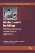
Previously the thermal properties of rammed earth have been studied in isolation using steady-state heat gain/loss models, while the main advantage of the material is in fact its dynamic behaviour and the utilisation of this with passive design. Some publications give values for the thermal resistance of rammed earth materials, which is their resistance to conduction of heat under steady-state conditions defined by d/λ (m2 K/W). According to Standards New Zealand (1998), in the absence of any laboratory test data the thermal resistivity (R) of a stabilised rammed earth (SRE) wall can be approximated as R = 2.04d + 0.12. The CSIRO have published some experimental data, along with Walker et al. (2005) in the Rammed Earth Design and Construction Guidelines book showing the significant relationship that exists between the bulk density of earth materials and their dry-state thermal conductivity as shown in Table 2.1.
Table 2.1
The correlation between bulk density and dry-state thermal conductivity for rammed earth materials (Walker et al., 2005)
2.2 Hygrothermal loads and modelling
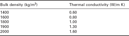
The hygrothermal behaviour of a material can be defined as the change in a material’s physical properties as a result of the simultaneous absorption, storage and release of both heat and moisture (liquid and/or vapour phase). In a building envelope these loads may be thermal or hygric and are experienced on both internal and external aspects. The thermal and hygric loads commonly experienced by a building are illustrated in Fig. 2.1. A building envelope protects the indoor environment from the outside, i.e. there will be large fluctuations in both temperature and humidity outside, but because of the envelope, only a minor part of these fluctuations is transmitted to the indoor environment. The heat and moisture fluxes that generate these loads may also change direction as the air temperature and relative humidity change throughout the day and also across the seasons. The principal hygrothermal loads experienced by the envelope can be summarised as:
2.1 Hygrothermal loads affecting a typical building (Künzel et al., 2005).
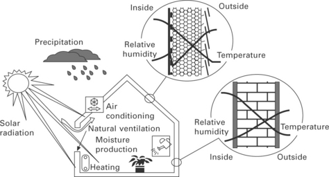
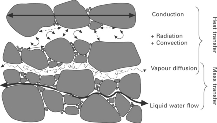
The hygrothermal behaviour of a material results from the fluxes of (i) heat transfer to and from the material, (ii) heat storage within the material, (iii) liquid and vapour moisture transfer to and from the material and (iv) moisture storage within the material. The possible directions of these fluxes are illustrated in Fig. 2.2. Each hygrothermal flux does not act independently, but instead all are inter-dependent and occur simultaneously in a complex manner.
2.2 Hygrothermal fluxes and their alternating directions across an earth wall (adapted from ASHRAE, 2009).
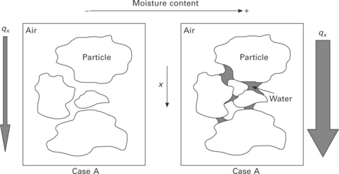
When a dry porous material is moved to a high(er) moisture content environment it may start to fill with water, assuming the porous structure is permeable, which can have the effect of dramatically increasing the thermal conductivity and thus the wall’s thermal resistance will be reduced. This is partially due to the capillaries within the material filling with water, which, in the case of soils, leads to the formation of menisci at points of inter- particle contact (Hall and Allinson, 2009a). These menisci form a ‘bridge’ increasing inter-particle contact area and allowing greater heat flux within the material as depicted by Fig. 2.3. A further consideration must be the transport of heat by convection within the pores which, in a partially saturated material, includes either liquid or water vapour. Where it is possible for the water to evaporate from larger pores, transport in the form of vapour, and then condense at another location within the material the heat flux increases dramatically due to the latent energy of vaporisation–condensation. This is a complex topic that can be studied in further detail by referring to ISO 10456 (1999) and Hall and Allinson (2010a), or from dedicated texts on transport phenomena such as Bird et al. (2001).
Alongside the hygrothermal building loads, knowledge of the hygrothermal functional properties of all construction materials used in the building envelope is also required for any predictive modelling of its behaviour. These properties include:
• Specific heat capacity (cp) - the amount of energy required to raise one unit of mass by one Kelvin (J/kg K) and at constant pressure, which can also be converted to volumetric heat capacity by multiplying by the material bulk density
• Moisture content-dependent heat capacity (cp*) – the heat capacity of a porous material increases significantly with the degree of saturation, since the specific heat capacity of water is comparably high, and so is a function of moisture content for partially- or fully saturated materials
• Bulk porosity (n) – the ratio of the volume of pore space to the total volume of a material, where the ratio of dry mass to total volume is bulk density (ρd)
• Thermal conductivity (λ) – the coefficient for thermal conduction through matter due to a temperature gradient
• Moisture content-dependent thermal conductivity (λ*) – thermal conductivity increases significantly with degree of saturation and so is a function of moisture content for partially or fully saturated materials
• Water vapour diffusion resistance factor (μ) – the ratio of the vapour diffusion resistance of air to the vapour diffusion resistance of the porous material
• Moisture storage function – the isothermal relationship between the equilibrium moisture content (EMC) of a porous material at each value of relative humidity from 0–100%, also referred to as the ‘sorption isotherm’
• Water absorption coefficient (Aw) – the rate of water (mass) absorption against the square root of elapsed time due to capillarity in a porous material, also known as the sorptivity (S).
The development and significance of numerical modelling in building physics has been growing for many years. However, until the advent of fully transient hygrothermal models, modelling of building fabric traditionally considered heat transfer/storage and moisture transfer/storage in isolation, to some degree. Two previously accepted standard building physics models are the Glaser Model and the Admittance Model, although other more recent models also exist such as the Heat Balance Method (ASHRAE, 2009). These have been the basis of many computer-based modelling packages such as EnergyPlus (USDE, 2007), IES Virtual Environment and TAS (EDSL, 2010) amongst others. According to BS EN 15026: 2007 (BSi, 2007) all hygrothermal models must include the following transport and storage phenomena:
• heat storage in dry building materials and any absorbed water
• heat transport by moisture-dependent thermal conduction
• latent heat transfer by vapour diffusion
• moisture storage by vapour sorption and capillary forces
• moisture transport by vapour diffusion
• moisture transport by liquid transport (surface diffusion and capillary flow).
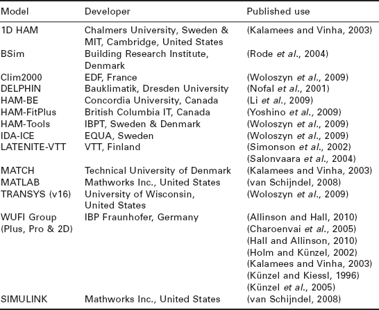
Some of the hygrothermal numerical models that have been developed are listed in Table 2.2. For further information refer to Materials for Energy Efficiency and Thermal Comfort in Buildings (Hall, 2010).
2.2.1 Calculation and results
The outputs from a hygrothermal numerical model can be categorised into two distinct sections:
1. temperature and heat flux distributions and their evolution
2. water content, RH and moisture flux distributions and their evolution.
The format of these results can be as numerical data for further input/analysis, or can be displayed graphically as a time-dependent simulation of the fluxes and distribution through a building envelope cross-section. Hygrothermal models allow the user to monitor many points throughout the envelope, including critical boundaries between differing materials. An example of this is the graphic output from the WUFI Pro v4.1 model shown in Fig. 2.4.
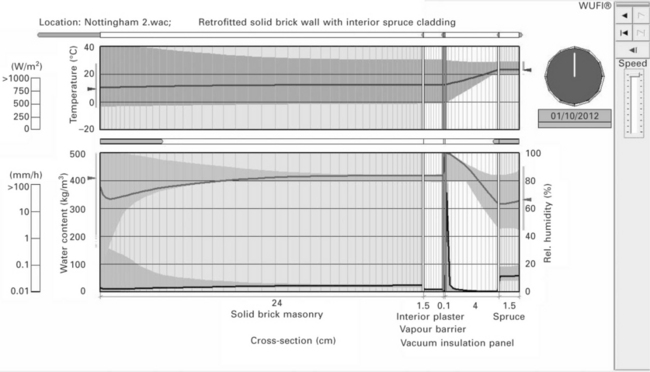
2.4 A graphical output from WUFI Pro v4.1 hygrothermal modelling software for a solid masonry wall with retrofit internal insulation based in Nottingham, UK, showing the temperature and moisture content profiles along with indicators of relative magnitude and direction of flux at the boundary between each material layer.
Interpretation of modelling results can be addressed in three stages:
1. The model requires validation to ensure all predicted results are accurate and consistent with physical modelling of the same/similar scenarios
2. Interpretation of heat and moisture levels on and within the building envelope
3. Post-processing of the results to predict corrosion, ageing, energy consumption/saving, susceptibility to rot and mould growth, etc.
The results, once validated, can be used to predict moisture levels in the envelope over a specified time scale (months, years, etc.). Specific materials in the envelope will have service limits for temperature and moisture content, and using the results one can predict whether these limits are being exceeded. It is also possible to predict the drying out of initial moisture from construction and performance of specialised envelope components such as selective vapour barriers and insulation elements. Post-processing of the results can be beneficial in predicting the formation of mould in critical areas (e.g. cold bridges), rotting and premature ageing of the envelope materials due to increased moisture levels, and corrosion of ferrous envelope components (e.g. steel wall ties). These issues are discussed in further detail in Moisture Control in Buildings by Trechsel (1994).
2.2.2 Validation and applications
The WUFI group of hygrothermal models have been extensively validated against physical models and field work in many studies. Both the 1-D version (WUFI Pro v4.1) (Hall and Allinson, 2010b) and the whole building energetic model version (WUFI Plus v1.2) have been used for validation of SRE walls and buildings by Allinson and Hall (2010). The research showed that SRE has very good potential for passive indoor climatic control by significantly reducing the amplitude of RH fluctuations, when compared to standard building materials (i.e. unpainted and painted plaster board), as well as having high thermal mass comparable to that of dense concrete. In another study, the drying of an autoclaved aerated concrete (AAC) roof was successfully simulated by Holm and Künzel (2002) to determine whether an unvented flat AAC roof would perform correctly without a vapour retarder, in order to avoid the issue of construction moisture being prevented from drying, which could lead to a net loss in the insulation value of the roof. The model was also successfully validated against field experiments on natural stone facades by Künzel and Kiessl (1996).
WUFI 2-D was validated against experimental results for assessing the performance of three different wall fabrics with different insulation and vapour barriers by Kalamees and Vinha (2003). The study was conducted by simulating wall behaviour under ambient Nordic climatic conditions from autumn to spring using three different models (1D-HAM, MATCH and WUFI 2D) and then validating these results against laboratory experiments. The study concluded that, whilst the experimental results validated all three of the models in general, some inaccuracies were found due to simplifications, limitations and/or approximations of the material properties in the model and also the limiting accuracy of the experimental measurements themselves.
The full energetic building (3D) version of the programme, WUFI Plus, has been accurately validated against field results for an unoccupied SRE test building that was monitored for a continuous period of 10 months by Allinson and Hall (2010). Künzel et al. (2005) validated the model against the humidity buffering performance of wood-lined rooms. Testing has also been performed in two custom-built test rooms at the IBP Fraunhofer facility in Germany (Künzel et al., 2004). One room was constructed using aluminium foil as the interior lining, leaving the room with negligible vapour permeability and hence sorption capacity, while the other room was lined with plasterboard to simulate a standard room. The addition of wood linings to the aluminium room allowed for assessment of the humidity buffering performance of the wood, and the results from the model were in close agreement with those from the experiments.
2.3 Thermal and hygric properties of earth materials
The material functional properties required as inputs for hygrothermal modelling are described in section 2.1. Experimental measurement of these properties is more involved than for steady-state properties as the majority are functions as opposed to single value coefficients. The thermal conductivity, for example, cannot be specified as a single value rather as a function of moisture content and so has a range of values from when the material is completely dry to when it is completely saturated and anywhere in between. The difference in these functional properties between one type of material and another is often significant. Before their hygrothermal behaviour can be accurately studied, these functional properties have to be experimentally determined. In the case of rammed earth, the specific heat capacity of the soil can be determined across a specified temperature range using Differential Scanning Calorimetry (DSC). However, this technique requires small samples of the order of 25 mg for testing and the soil is composed of a range of mineral types. A more common approach for non- homogeneous materials such as soil is to measure their bulk heat capacity by determining the dominant mineral type(s) and then multiplying the specific heat capacity for that mineral by the bulk density of the material (ρ Cp), which gives the volumetric heat capacity. If the ‘soil’ is a blend of more than one soil/mineral type, and contains cement or another stabiliser, then the bulk heat capacity can be calculated in terms of the mass proportion of each phase. This approach can be further extended to include the relative water content, w, so that the moisture content-dependent heat capacity can be calculated using (Hall and Allinson, 2008):
The thermal conductivity of earth materials can be experimentally determined using the heat flow meter method, either in the dry state as described in ISO 8301 (1991), or in the partially or fully saturated state in accordance with ISO 10051 (1996). The degree of saturation, S, in soils is defined in Chapter 8 (Augarde) and ranges from 0 when dry up to 1 when fully saturated. Thermal conductivity in soils, concrete and similar materials are often observed to increase linearly with S. The slope of this line can obviously be assessed by linear regression and gives a value called the moisture factor, mf, which is a measure of the material’s sensitivity to moisture content in terms of its thermal conductivity. The moisture content-dependent thermal conductivity can therefore be determined using λ* = λ(1 + S × mf). The vapour permeability of earth materials can be assessed using the wet cup/dry cup method as detailed in BS EN ISO 12572:2001 ‘Hygrothermal performance of building materials and products – determination of water vapour transmission properties’ (BSi, 2001). In this case the motivating potential for vapour to transport through the pore structure of the material is the partial vapour pressure (relative humidity) differential. Liquid water transport is commonly assessed by determining the sorptivity (also known as the water absorption coefficient) by the gravimetric partial immersion method as described in Hall et al. (1984). This applies to partially saturated materials where the motivating potential for water absorption (and transport within the material) is capillary potential, sometimes referred to as ‘suction’. In the case of a fully saturated specimen the capillary potential is zero and hence the liquid will only transport within the pore network if there is an applied pressure differential. In this case the hydraulic conductivity is assessed with reference to Darcy’s Law. Clearly, the geometry of the pore network inside the earth materials determines the hygrothermal functional properties as illustrated in Fig. 2.5:
2.5 Illustration of the origins of hygrothermal functional properties within the micro-structure of rammed earth (Hall and Allinson, 2009b).
A range of hygrothermal functional properties for a limited number of stabilised rammed earth materials have been published by Hall and Allinson (2009b), as summarised in Table 2.3.
Table 2.3
Hygrothermal functional properties for three contrasting stabilised rammed earth materials (Hall and Allinson, 2009)
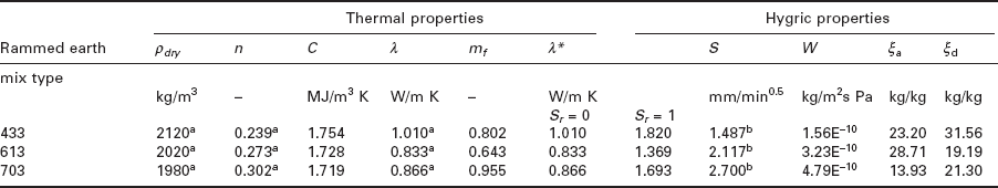
An important point is that the hygroscopic moisture storage function (ξ) refers to the gradient of the middle portion of the sorption or desorption isotherm. The actual input for a hygrothermal model is the entire sorption isotherm, which represents the equilibrium moisture content of the material at every point between 0 and 100% relative humidity. Further details of the heat and mass transport and storage process discussed in this section can be found in Hall and Allinson (2010a), while further details of the experimental data presented above and the test apparatus can be found in Hall and Allinson (2008). Significantly, the hygrothermal properties of SRE materials are thought to be ‘tunable’ through careful modification of the internal pore structure, either by changing the particle size distribution of the soil, or through addition of clay minerals.
2.4 Hygrothermal behaviour and passive air conditioning
At the outside surface interface, rammed earth walls exchange heat by convection and radiation, and moisture by vapour exchange or by absorbing rain water. In a similar fashion, the inside wall surfaces interact with the indoor environment by exchanging both heat and water vapour and, as a result, can greatly influence the indoor air temperature and relative humidity. Obviously the hygrothermal functional properties of the earth wall material determine its behaviour under changing hygrothermal loads. Some earth materials have higher density and/or volumetric heat capacity and so are able to absorb, store and release larger quantities of heat energy, which, depending upon the rate of thermal diffusion can help to buffer variation of indoor air temperatures. In a similar way, some earth materials are able to absorb, store and release different amounts of water vapour, and depending on the quantity and rate of diffusion, can be used to buffer indoor relative humidity variation. In general terms, published data suggest that SRE materials can be identified as having both high thermal mass and a high hygric mass so can be used for both air temperature and relative humidity buffering. Unlike brick, timber or plastered walls, due to their natural aesthetics, rammed earth walls are almost always presented without any internal rendering, paint or wallpaper and so are in direct contact with the indoor air.
The passive temperature and humidity-buffering behaviour of rammed earth materials have been monitored, and to some extent exploited, in several modern earth buildings before. Few published studies have been conducted to determine which micro-structural material properties control this behaviour, or indeed how this understanding could be further utilised to optimise the material behaviour in a selective manner. Some case studies have been used to both measure and demonstrate the increased energy efficiency that can be gained when SRE walls are used for temperature buffering in domestic buildings. An electronically monitored SRE house in Sydney, Australia, for example, was left unoccupied and with no curtains for over a year and yet internal sensor readings recorded over that period showed an average annual indoor temperature range of between 18°C and 27°C, compared with an outdoor temperature range of between 7°C and 42°C (Mortensen, 2000). Similarly, a two-storey SRE office building in New South Wales, Australia, was monitored and displayed excellent thermal performance throughout a hot summer period due to peak temperature reduction by passive cooling and also dehumidification (Taylor and Luther, 2004). As a, result the amount of energy required to meet the heating and cooling loads in each of these buildings was significantly lower than that of conventional buildings. Ironically, under the CSIRO energy efficiency rating scheme, these buildings were incapable of attaining a high score because the steady state thermal resistance (R, m2 K/W) of the SRE walls was too low. However, this factor is simply a measure of the wall’s resistance to heat conduction.
An SRE test building, located in Leicestershire, UK, was constructed by Earth Structures (Europe) Ltd using the Australian-style formwork and pneumatic compaction techniques described in Chapter 22 (Lindsay). The air temperature and relative humidity was monitored in one of the rooms at 30-minute intervals for the period 4 July 2008 to 1 April 2009 as part of a published study conducted by Dr Hall and Dr Allinson at the University of Nottingham. The room measured 3.2 ![]() 2.5 m internally and the SRE walls were of the insulated cavity design comprising inner and outer leaves 175 mm thick plus internal wall ties and 50 mm extruded polystyrene cavity insulation. Further details of the material properties and instrumentation used for monitoring can be obtained from Allinson and Hall (2010). Detailed local weather data were also obtained over the monitoring period. The energetic hygrothermal building energy modelling package WUFI Plus v1.2 was used to predict the indoor air temperature and humidity for the SRE test room over the same period. This was validated to a high degree of accuracy against the data obtained from monitoring. This enabled the model to be expanded to include, for example, different hypothetical wall materials and occupancy patterns to compare and contrast the behaviour of the SRE walls with conventional materials, and then assess what effect they had on passively buffering air temperature and relative humidity. The example chosen for simulation and analysis was a bedroom occupied by two adults between 22:00 and 06:00 each day. The data showed that the SRE walls significantly reduced the amplitude of RH fluctuations, during both summer and winter periods, when compared to walls that were covered with conventional materials, e.g. painted plaster board and aluminium foil vapour barriers (as commonly applied beneath some plasterboard coatings). This is illustrated by Fig. 2.6, which shows the simulated RH variation across a typical week in summer. These results were obtained assuming that the room was completely unconditioned by mechanical heating, ventilation or air conditioning (HVAC) and so may not always provide adequate thermal comfort, for example on very hot or very cold days, where an additional ‘top up’ by mechanical systems may be required.
2.5 m internally and the SRE walls were of the insulated cavity design comprising inner and outer leaves 175 mm thick plus internal wall ties and 50 mm extruded polystyrene cavity insulation. Further details of the material properties and instrumentation used for monitoring can be obtained from Allinson and Hall (2010). Detailed local weather data were also obtained over the monitoring period. The energetic hygrothermal building energy modelling package WUFI Plus v1.2 was used to predict the indoor air temperature and humidity for the SRE test room over the same period. This was validated to a high degree of accuracy against the data obtained from monitoring. This enabled the model to be expanded to include, for example, different hypothetical wall materials and occupancy patterns to compare and contrast the behaviour of the SRE walls with conventional materials, and then assess what effect they had on passively buffering air temperature and relative humidity. The example chosen for simulation and analysis was a bedroom occupied by two adults between 22:00 and 06:00 each day. The data showed that the SRE walls significantly reduced the amplitude of RH fluctuations, during both summer and winter periods, when compared to walls that were covered with conventional materials, e.g. painted plaster board and aluminium foil vapour barriers (as commonly applied beneath some plasterboard coatings). This is illustrated by Fig. 2.6, which shows the simulated RH variation across a typical week in summer. These results were obtained assuming that the room was completely unconditioned by mechanical heating, ventilation or air conditioning (HVAC) and so may not always provide adequate thermal comfort, for example on very hot or very cold days, where an additional ‘top up’ by mechanical systems may be required.
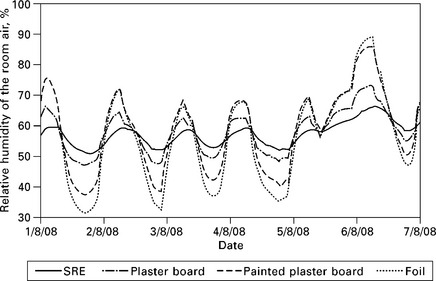
2.6 The simulation variation in relative humidity, due to different wall materials, in a bedroom over a typical week in summer (Allinson and Hall, 2010).
The results of the model were further analysed taking into account mixed mode operation comprising the ‘active’ temperature and humidity regulation by a mechanical HVAC system in the room, and also the ‘passive’ temperature and humidity regulation of the SRE walls. The mixed mode operation was considered both for continuous operation in parallel with the passive system, and in intermittent operation where the mechanical HVAC operation was governed by thermostat and humidistat set point values. These set points can be varied and provide precise control over the indoor thermal comfort. In this study they were set to an air temperature of between 18 and 20°C, and between 40 and 50% RH, which represents a very closely controlled indoor climate. Adequate thermal comfort may be achieved with much wider parameters in the set points, which obviously reduces overall energy consumption in its own right, for example 18–23°C and 40–70% RH. The intention, however, is that the ‘energy free’ passive system should be used in preference to minimise the amount of energy needed to operate the mechanical system. Further details of the modelling parameters can be obtained from Allinson and Hall (2010). The results showed that the SRE walls were very responsive to periods of high internal humidity loads and responded by absorbing moisture vapour for later release when the humidity decreased. When used in conjunction with constant mode mechanical HVAC, there was a significant reduction in the energy required for humidification and dehumidification energy demand when compared to the conventional wall materials, as shown by the data in Table 2.4.
Table 2.4
Predicted daily HVAC energy consumption for constant mixed mode operation with SRE and conventional wall materials (Allinson and Hall, 2010
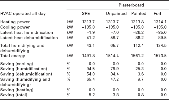
The heating and cooling energy loads were not significantly different, as predicted, since the test room had a very simple geometry with minimal glazing and therefore could not capitalise on the benefits of passive solar design discussed in Chapter 5 (Rongen). Further studies would be required to quantify this behaviour. When the intermittent mode HVAC was simulated, there was still an overall reduction in humidification and dehumidification energy use. However, the reductions for the SRE wall were less than that for the impermeable case because the SRE absorbed significant amounts of water vapour while the HVAC system was inoperative. This is highlighted by the data shown in Table 2.5.
Table 2.5
Predicted daily HVAC energy consumption for intermittent mixed mode operation with SRE and conventional wall materials (Allinson and Hall, 2010)
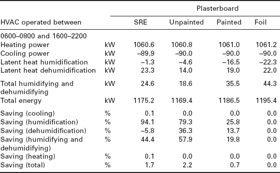
When the HVAC became operative it attempted to remove this excess moisture from the wall causing a slight increase in energy use. This highlights the need for a detailed understanding of building physics at the design stage. The potential exists to make significant energy savings and increased thermal comfort using SRE walls over conventional materials, but if used inappropriately in conjunction with mechanical HVAC systems can actually have the reverse effect.
2.5 Indoor health and air quality
The indoor air quality is the most significant thing to affect occupants’ thermal comfort and it is widely believed to cause a variety of issues. Physiologically, poor air quality decreases work productivity especially under a high-humidity environment (Tsutsumi et al., 2007) whilst economically it can lead to significant energy waste (Osanyintola and Simonson, 2006). The study of ‘thermal comfort’ is often focused on the air temperature range, whilst the consideration of RH is often neglected. As previously discussed, the enthalpy (latent energy) associated with high RH in air cannot be overlooked. It has been suggested that a range of between 30 and 80% RH may not produce significant problems for human health, but that a range of 30 to 60% RH and an air temperature range of 18 to 24°C is preferable (Crump et al., 2002). Another study on the effect of humidity on human comfort in office spaces in a hot/humid climate suggests that the appropriate range may be 40 to 70% RH (Tsutsumi et al., 2007). A hot–humid environment can cause sweating, whilst a low-humidity environment can cause dryness of the eyes and skin (Crump et al., 2002). Hines et al. (1993) concluded that the most advisable humidity range for thermal comfort and occupant health in buildings is between 40 and 60%.
In terms of the currently available data, the DTi-sponsored study of rammed earth for UK housing, led by the University of Bath, alluded to the importance of thermal mass for increasing energy efficiency and thermal comfort, but only provided generic values for the thermal conductivity and specific heat capacity of a limited range of earth materials (Walker et al, 2005). The product information provided by the Affiliated Stabilised Earth Group (ASEG, 2003) of SRE contractors specifies an estimated thermal time lag of 6–8 hours in a 300 mm-thick wall. It is evident that materials which can rapidly absorb significant quantities of moisture vapour can buffer RH changes (i.e. hygric mass) in the same way that materials which absorb large quantities of heat can buffer air temperature changes (i.e. thermal mass). Covering these materials with low vapour permeability layers (e.g. paints) dramatically reduces the moisture buffering behaviour (Kalamees et al, 2009). The interrelation between indoor air quality and RH should be considered as having a direct influence on occupants’ comfort and health. Wolkoff and Kjrergaard (2007) state that interior spaces with low humidity can result in some clinical symptoms such as dry eyes and sensory irritation, whilst the occurrence of mould growth can increase when surfaces are in contact with air that is very humid. Previous research has shown that SRE materials can reduce the frequency of high humidity periods at the wall surface and were therefore judged to be highly beneficial in reducing mould growth in buildings (Allinson and Hall, 2010). SRE materials are good moisture-buffering materials and are normally left uncovered inside buildings, therefore ideally suited to passive humidity control. It has been concluded from previous research that SRE walls have the potential to improve thermal comfort, improve indoor air quality and reduce the energy demand in buildings, however care should be taken if used in conjunction with mechanical HVAC system design including the conditioning strategy and ventilation rate.
2.5.1 Measuring indoor health and air quality
There are six basic parameters that define an occupant’s comfort environment (Parsons, 2003):
The first four are referred to as the ‘environmental factors’, while the final two are ‘personal factors’. The four environmental factors can be measured directly. In reference to the personal factors, however, the human body is constantly subjected to the influences of the environmental ones. In an attempt to regulate itself at a constant temperature, it uses counter processes to act against these influences, e.g. evaporation of sweat for skin surface cooling, respiratory evaporation, conduction, convection via the blood, radiation and metabolic storage. This constant loop process is called thermoregulation, and clothing and level of activity also contribute to this. The thermoregulation loop is essentially a heat-balance loop and can therefore be represented by a heat-balance equation (ASHRAE, 2009). In his text Fanger also proposed a similar equation (Fanger, 1972):
While it is possible to easily measure and monitor the environmental and personal factors contributing towards thermal comfort, it is less simple to measure the physiological phenomena. As thermal comfort is subjective, it follows that the most efficient method of measuring the physiological elements of thermal comfort is to ask that person. These subjective techniques fall within two categories: personal and environmental, i.e. how the person feels (hot/cold) and what is their acceptance and/or tolerance of the thermal environment. In both techniques, scales are used to give a qualitative indication of the person’s response. The Predicted Mean Vote (PMV) and Percentage of People Dissatisfied (PPD) are primarily used to measure thermal comfort. PMV and PPD can be calculated using the standard BS EN ISO 7730 (BSi, 2005), while subjective judgement scales can be found in BS EN ISO 10551 (BSi, 2001).
Pollution of the indoor air can also affect occupants’ comfort due to poor air quality. The causes of this pollution will generally stem from one of (or a combination of) the following factors (Maroni et al, 1995):
• poorly maintained environments
• poor ventilation or air exchange
• biological contamination from poor moisture control strategies
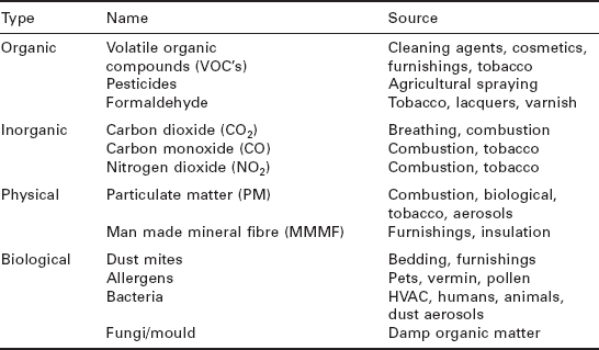
This means that the quality of indoor air can be affected by sources within the building and from sources outside through air infiltration into the space. Typical pollutants found in the indoor environment can be seen in Table 2.6.
With respect to the RH, the indoor air quality (IAQ) and the biological problems associated with it are summarised in Figure 2.7. The ‘optimum zone’ is the acceptable range of RH that will minimise pollution within the indoor air and improve the IAQ, quantified as 30–55% RH. Measuring the factors affecting IAQ involves similar measures to those employed in analysing thermal comfort, i.e. temperatures, RH levels, air exchange rates, pollutant concentrations, occupant behaviour and perception, but may also involve medical examinations to determine health issues.
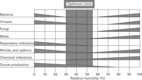
2.7 The humidity-related effects on health and indoor air quality (Simonson et al., 2001).
Guidelines for IAQ measurement can be found in the international standard BS ISO 16814:2008 (BSi, 2008). The perceived air quality (PAQ) method of expressing IAQ uses subjective scales derived from questionnaires similar to those used in thermal comfort surveys, i.e. PPD. According to the standard, one of two methods can be used to express IAQ:
2.6 Sources of further information
The following professional organisations offer membership, annual conference events and workshops, and relevant publications including official guidance documents:
• The Chartered Institute of Building Services Engineers (CIBSE), 222 Balham High Road, London, SW12 9BS. Tel + 44 (0)20 8675 5211, Fax + 44 (0)20 8675 5449
• American Society of Heating, Refrigeration and Air Conditioning Engineers (ASHRAE), 1791 Tullie Circle, N.E., Atlanta, GA 30329, USA.
An excellent source of further reference material is international peer- reviewed journals, which publish high-quality scholarly articles of direct relevance to the topics discussed in this chapter. Strongly recommended journals for the topics covered in this chapter include Building and Environment, Energy and Buildings, Applied Thermal Engineering, Construction and Building Materials, Cement and Concrete Composites, Journal of Building Physics, The American Society of Civil Engineers (ASCE) family of journals and the Proceedings of the Institute of Civil Engineers (ICE) family of journals.
2.7 References
Allinson, D., Hall, M. Hygrothermal analysis of a stabilised rammed earth test building in the UK. Energy and Buildings. 2010; 42:845–852.
ASEG, New Earth Structures [brochure], available from. Affiliated Stabilised Earth Group, 2003. [PO Box 161, North Fremantle, 6159, Australia].
ASHRAE, ASHRAE Handbook – Fundamentals (SIEdition). American Society of Heating, Refrigerating and Air-Conditioning Engineers, 2009. [Atlanta, Ga., USA].
Bird, R.B., Stewart, W.E., Lightfoot, E.N. Transport Phenomena – 2nd Edition. Chichester: Wiley; 2001.
BSiBS EN ISO 10551:2001: Ergonomics of the thermal environment - Assessment of the influence of the thermal environment using subjective judgement scales. London: British Standards Institute, 2001.
BS EN ISO 12572Hygrothermal performance of building materials and products – Determination of water vapour transmission properties. London: British Standards Institute, 2001.
BSiBS EN ISO 7730:2005: Ergonomics of the thermal environment – Analytical determination and interpretation of thermal comfort using calculation of the PMV and PPD indices and local thermal comfort criteria. London: British Standards Institute, 2005.
BSiBS EN 15026 2007: Hygrothermal performance of building components and building elements – Assessment of moisture transfer by numerical simulation. London: British Standards Institute, 2007.
BSiBS EN ISO 16814: 2008: Building environment design – Indoor air quality Methods of expressing the quality of indoor air for human occupancy. London: British Standards Institute, 2008.
Charoenvai, S., Khedari, J., Hirunlabh, J., Asasutjarit, C., Zeghmati, B., Quenard, D., Pratintong, N. Heat and moisture transport in durian fiber based lightweight construction materials. Solar Energy. 2005; 78:543–553.
Crump, D., Raw, G., Upton, S., Scivyer, C., Hunter, C., Hartless, R. A protocol for the assessment of indoor air quality in homes and office buildings. In: BRE Report BR 450. Watford: BRE Bookshop; 2002.
EDSL available at. EDSL TAS industry-leading building modelling and simulation. 2010 www.edsl.net/main/Software.aspx [(accessed 14 July 2010)].
Fanger, P.O. Thermal Comfort. New York: McGraw-Hill; 1972.
Hall M.R., ed. Materials for Energy Efficiency and Thermal Comfort in Buildings. Cambridge: Woodhead Publishing, 2010.
Hall, M., Allinson, D. Assessing the moisture-content dependent parameters of stabilised earth materials using the cyclic-response admittance method. Energy and Buildings. 2008; 40(11):2044–2051.
Hall, M.R., Allinson, D. Assessing the effects of soil grading on the moisture content-dependent thermal conductivity of stabilised rammed earth materials. Applied Thermal Engineering. 2009; 29:740–747.
Hall, M., Allinson, D. Analysis of the hygrothermal functional properties of stabilised rammed earth materials. Building and Environment. 2009; 44(9):1935–1942.
Hall, M.R., Allinson, D. Heat and mass transport processes in building materials. In: Hall M.R., ed. Materials for Energy Efficiency and Thermal Comfort in Buildings. Cambridge: Woodhead Publishing, 2010.
Hall, M.R., Allinson, D. Transient numerical and physical modelling of temperature profile evolution in stabilised rammed earth walls. Applied Thermal Engineering. 2010; 30:433–441.
Hall, C., Hoff, W.D., Nixon, M.R. Water movement in porous building materials – VI: Evaporation and drying in brick and block materials. Building and Environment. 1984; 19(1):13–20.
Hines A.L., Ghosh T.K., Loyalka S.K., Warder R.C., eds. Indoor Air-Quality and control. Englewood Cliffs, NJ, USA: Prentice-Hall, 1993.
Holm, A.H., Künzel, H.M. Practical application of an uncertainty approach for hygrothermal building simulations-drying of an AAC flat roof. Building and Environment. 2002; 37:883–889.
ISO 8301. Thermal insulation – Determination of steady-state thermal resistance and related properties – Heat flow meter apparatus. Genève, Switzerland: International Organization for Standardization, 1991.
ISO 10051. Thermal insulation – Moisture effects on heat transfer – Determination of thermal transmissivity of a moist material. Genève, Switzerland: International Organization for Standardization, 1996.
ISO 10456. Building materials and products: Procedures for determining declared and design thermal values. Genève, Switzerland: International Organization for Standardization, 1999.
Kalamees, T., Korpi, M., Vinha, J., Kurnitski, J. The effects of ventilation systems and building fabric on the stability of indoor temperature and humidity in Finnish detached houses. Building and Environment. 2009; 44(8):1643–1650.
Kalamees, T., Vinha, J. Hygrothermal calculations and laboratory tests on timber-framed wall structures. Building and Environment. 2003; 38:689–697.
Künzel, H.M., Kiessl, K. Calculation of heat and moisture transfer in exposed building components. International Journal of Heat and Mass Transfer. 1996; 40:159–167.
Künzel, H.M., Holm, A., Sedlbauer, K., Antretter, F., Ellinger, M. Moisture buffering effects of interior linings made from wood or wood based products: IBP Report HTB-04/2004/e. In: Technical investigation commissioned by Food Focus Oy and the German Federal Ministry of Economics and Labour. IBP, Institutsteil Holzkirchen; 2004.
Künzel, H.M., Holm, A., Zirkelbach, D., Karagiozis, A.N. Simulation of indoor temperature and humidity conditions including hygrothermal interactions with the building envelope. Solar Energy. 2005; 78:554–561.
Li, Q., Rao, J., Fazio, P. Development of HAM tool for building envelope analysis. Building and Environment. 2009; 44:1065–1073.
Maroni, M., Seifert, B., Lindvall, T. Indoor Air Quality: A comprehensive Reference Book. Amsterdam: Elsevier; 1995.
Mortensen, N. The naturally air conditioned house, 2000. www.dab.uts.edu.au/ebi/index [[online] Earth Building Research Forum, University of Technology Sydney, Australia, available at, (last accessed 25 March 2004)].
Nofal, M., Straver, M., Kumaran, M.K., Comparison of four hygrothermal models in terms of long-term performance assessment of wood-frame constructions. Eighth Conference on Building Science & Technology, Solutions to Moisture Problems in Building Enclosures, 2001. [Toronto, Canada, pp. 118–138].
Osanyintola, O.F., Simonson, C.J. Moisture buffering of hygroscopic building materials: Experimental facilities and energy impact. Energy and Buildings. 2006; 38:1270–1282.
Parsons, K.C. Human Thermal Environments: The Effects of Hot, Moderate, and Cold Environments on Human Health, Comfort, and Performance. London: Taylor & Francis; 2003.
Rode, C., Mendes, N., Karl, G. Evaluation of moisture buffer effects by performing whole-building simulations. ASHRAE Transactions. 2004; 110:783–794.
Salonvaara, M., Ojanen, T., Holm, T., Kunzel, H., Karagiozis, A., Moisture buffering effects on indoor air quality – experimental and simulation results. Proceedings (CD) of the Performance of Exterior Envelopes of Whole Buildings IX International Conference, Florida, USA, 2004.
Simonson, C.J., Ojanen, T., Salonvaara, M. Improving Indoor Climate and Comfort with Wooden Structures. Espoo, Finland: Technical Research Centre of Finland, 2001.
Simonson, C.J., Salonvaara, M., Ojanen, T. The effect of structures on indoor humidity – possibility to improve comfort and perceived air quality. Indoor Air. 2002; 12:243–251.
Standards New Zealand. NZS 4298: 1998 Materials and Workmanship for Earth Buildings, 1998. [Wellington, New Zealand].
Taylor, P., Luther, M.B. Evaluating rammed earth walls: a case study. Solar Energy. 2004; 76:79–84.
Trechsel, H.R. Moisture Control in Buildings. Philadelphia, USA: Astm Intl; 1994.
Tsutsumi, H., Tanabe, S., Harigaya, J., Iguchi, Y., Nakamura, G. Effect of humidity on human comfort and productivity after step changes from warm and humid environment. Building and Environment. 2007; 42(12):4034–4042.
USDE, US Department of Energy, EnergyPlus 2.0 – Major release – New functionality. 2007. PDF document available at http://apps1.eere.energy.gov/buildings/energyplus/pdfs/energyplus_v2_brochure.pdf [(accessed 14 July 2010)].
Van Schijndel, A.W.M. Estimating values for the moisture source load and buffering capacities from indoor climate measurements. Journal of Building Physics. 2008; 31:319–331.
Walker, P., Keable, R., Martin, J., Maniatidis, V. Rammed Earth: Design and Construction Guidelines. Watford: BRE Bookshop; 2005.
Wolkoff, P., Kjsrgaard, S.K. The dichotomy of relative humidity on indoor air quality. Environment International. 2007; 33(6):850–857.
Woloszyn, M., Kalamees, T., Abadie, M., Steeman, M., Kalagasidis, A. The effect of combining a relative-humidity-sensitive ventilation system with the moisture-buffering capacity of materials on indoor climate and energy efficiency of buildings. Building and Environment. 2009; 44:515–524.
Yoshino, H., Mitamura, T., Hasegawa, K. Moisture buffering and effect of ventilation rate and volume rate of hygrothermal materials in a single room under steady state exterior conditions. Building and Environment. 2009; 44:1418–1425.
2.8 Appendix: nomenclature
Aw water absorption coefficient kg/m2 s1/2
bm moisture effusivity kg/(m2 Pa s1/2)
cp constant pressure specific heat capacity J/kg K
Eres rate of evaporative heat loss from respiration W/m2
Esk rate of evaporative heat loss from skin W/m2
M rate of metabolic heat production W/m2
Psat saturation vapour pressure Pa
Qsk total rate of heat loss from skin W/m2
Qres total rate of heat loss through respiration W/m2
W rate of mechanical work accomplished W/m2
β thermal effusivity W s1/2/m2 K
δp water vapour permeability kg/m s Pa
μ water vapor diffusion resistance factor –