Weathering and durability of earthen material and structures
Abstract:
Durability of earthen structures is mainly dependent on the action of water on the walls. In this chapter, the relevance of the current tests measuring the resistance of earthen material to water is analysed and some pertinent tests are suggested to corresponding domains of application. The second part of the chapter deals with the use of plaster to increase durability. The validation of the plaster is proposed thanks to two in situ tests: the shrinkage test and the shear test for surface coatings. The long-term performance of earthen material is then analysed through research that has been conducted on walls exposed to natural climatic conditions for several years.
11.1 Introduction
Durability of building materials can be defined as their resistance to functional deterioration over time. The durability of earthen structures is mainly related to the action of water on the walls. In this chapter, firstly, mechanisms of increasing water content in earthen walls are introduced. Next, we present current tests for assessing the durability of earthen materials in the laboratory consisting of the ‘spray test’, the ‘drip test’, the ‘wire brush test’, the ‘saturated to dry strength ratio’, the ‘slake durability test’, the ‘rainfall test’ and the ‘stability in static water test’. The shrinkage test and the shear test for surface coatings are also presented. The results of research conducted on walls exposed to natural climatic conditions for several years are presented, which give an insight into the long-term performance of earthen material. Finally, we discuss the relevance of the current tests and suggest some pertinent tests for corresponding domains of application.
The durability of building materials can be defined as their resistance to functional deterioration over time (Heathcote, 2002). So, during an earthen wall life cycle, many factors can affect its sustainability:
• loss of mechanical strength due to a significant increase of moisture in the wall (capillary rise, pipe damage, infiltration of water during the rains or floods)
• erosion on the surface of walls due to incident rainfall and rain splash at the foot walls
• damage affecting the wall material due to freeze–thaw owing to the presence of water in the wall
All these risk factors can be minimised with appropriate architectural design or technical solutions. For example, earth stabilisation (see Chapter 9) reduces abrasion, damage caused by insects or plants and erosion due to water. Coating (see Section 11.5) reduces the penetration of water and therefore the harmful effects of freezing.
Durability of earthen structures is mainly related to the action of water on the walls. This action is manifested primarily by increase of water content and erosion of earthen walls. The first problem is mainly due to capillary flow (from ground or surface). The second comes from incident rainfall. They are the two main subjects that will be discussed in this chapter. The points mentioned above will be detailed in the following sections.
11.2 Water content increase in earthen walls
11.2.1 The subsequent decrease in mechanical strength
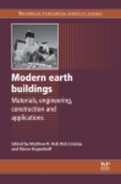
Clay particles and siliceous particles are hydrophilic in nature (Morton and Buckman, 2008). This is the reason why, at microscopic scale, when earth material contains a large amount of water, mechanical bond strength between clay and grains (sand, gravel, etc.) decreases, leading to a reduction in the internal cohesion of the material. This translates to mechanical strength reduction of the material at macroscopic scale. Figure 11.1 shows an example of variation of compressive strength versus water content of unstabilised rammed earth specimens (9% clay content by dry weight).
11.1 Decrease in compressive strength with an increase in the water content of unstabilised rammed earth samples, 9% clay content (ENTPE).
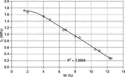
For stabilised earth material, increase in water content also leads to a decrease in compressive strength. For cement-stabilised compressed earth blocks (CEBs) in studies by Walker (1995), Krishnaiah and Suryanarayana (2008) and Reddy and Kumar (2011), the ratio between average saturated and dry compressive strengths varied between 0.13 and 0.95, and was largely dependent on clay content (Fig. 11.2). The reason is that when clay plates are inserted between cement particles and aggregates, the bonds between these particles become hydrophilic. Therefore, cohesion decreases when water content increase.
When the ratio of cement to clay and total soil is sufficiently high (which is generally above 10% by weight), cement particles can cover all the clay particles and the granular particles, and the material becomes insensitive to water. These materials can be used even in the case of retaining walls.
11.2.2 Increase in freeze–thaw effects
On the one hand, freeze–thaw damage depends on the properties of the material itself, for example material manufactured with a sandy soil has a lower freeze–thaw risk compared to a clayey soil because larger micropores can more easily tolerate the expansion of water and it causes less damage (Minke, 2000). On the other hand, freeze–thaw damage also depends on the moisture content of the material during the freeze–thaw cycles: higher water content causes more harmful expansion in material micropores. The first element (material properties) depends on the choice of soil and construction techniques (rammed earth, adobe, CEB, etc.) which are presented in other chapters of this book. The second element (water content) is related to the ability of water to ingress into the material (by rain or capillarity from the soil).
11.2.3 Increase in shrinkage and efflorescence
An increase in water content tends to result in expansion of clay minerals. The amplitude of the swelling depends on the amount and the types of clays (montmorillonite, illite, smectite, kaolinite, etc.). After drying, clay shrinkage can create shrinkage cracks. These cracks will facilitate water access into the earth material during the next cycles of wetting and drying.
Moreover, soluble salts are often dissolved and redeposited on the wall surface where evaporation is occurring, and the resultant crystalline deposits are referred to as efflorescence (Hall and Djerbib, 2004, Grossein, 2009).
11.2.4 Causes of water content increase
Entry of water into earthen walls can be caused by a number of different mechanisms but is primarily due to wind-driven rainfall and absorption from the surrounding ground. Before water can penetrate a building enclosure, three conditions must exist simultaneously (Killip and Cheetham, 1984): there must be water on the wall, a route for it to travel on and a force to move it.
In earthen walls, the route for water migration is the open microporous network of the material. The force can be capillary suction, wind pressure or differential vapour pressure.
11.2.5 The mechanism of erosion
At the microscopic scale, the factor affecting erosion is the bond strength of particles, which is an intrinsic characteristic of the material. At macroscopic scale, the two predominant factors that determine the magnitude of erosion of the surface of earthen walls are the water content of the wall and the kinetic energy of incidental rain drops. Indeed, as mentioned above, with significant water content, internal cohesion of the material of the wall decreases. The material becomes more susceptible to erosion by rain. This is why, for the same amount of water, a strong but short rainfall is less erosive than prolonged rainfall (Heathcote, 1995). In the latter case, water has more time to penetrate the material, which reduces its resistance to erosion. This effect is more harmful than the increase in kinetic energy of incidental raindrops.
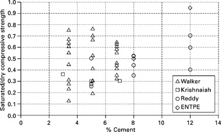
Kinetic energy of incidental raindrops depends firstly on the intensity of the rain – the stronger the force with which raindrops hit the wall, the more it is eroded – and secondly on the angle of the rainfall. The angle at which the raindrops beat the wall surface is determined by the speed of the wind. If there is no wind, raindrops will fall vertically and there will be no erosion. The kinetic energy is maximum for a 90° angle, but erosion will be favoured for a lower impact angle thanks to the digging effect (Fig. 11.3).
In the tropics, another important surface erosion factor of earthen walls is the water flow (Kerali and Thomas, 2004). Indeed, when water flow takes place on the wall surface, at grain scale, it creates a negative pressure, which increases the wall surface erosion, called cavitation erosion (ACI, 1998). This cavitation erosion is the reason why erosion is greater on a rough surface (e.g. adobes) than on a smooth one (e.g. rammed earth) (Heathcote, 1995).
11.3 Strategies to increase the durability of earth walls
Following what is mentioned in the previous section, to increase the durability of earth walls, they must be left at the ‘dry’ state and therefore it is necessary to prevent excess moisture sources in the walls.
11.3.1 Cutting the capillary rise
A choice that is systematically applied in new earthen constructions is to add insulation layers to protect against capillary rise from the ground. A recommended option is to use a basement to firstly decrease capillary rise and secondly protect the wall against rain-splash. The basement can be made of concrete, stone masonry, bricks or stabilised earth materials.
A solution that is often used in France is ‘canals’ filled with gravel surrounding the exterior walls to facilitate the evaporation of water in the soil under the wall, which helps to reduce the capillary action to the wall (Fig. 11.4).
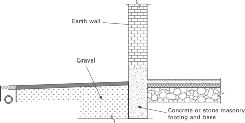
A damp-proofing barrier is often provided along the interface between the footing or plinth and the base of the earth wall. Heavy duty plastics-based damp-proof coursing materials (Walker et al., 2005) or bitumen (Bui et al., 2009a) are commonly used. However, in the case of rammed earth, the damp-proofing material should be capable of withstanding ramming without damage. To limit the possible risk of moisture build-up and damage at the interface between the rammed earth base and the permeable damp-proofing barrier, the barrier could be placed lower down the plinth beneath a course of bricks or similar.
11.3.2 Roof design
Wall erosion is often alleviated by good architectural design that ‘cover’ the walls as much as possible by roof
11.3.3 Stabilisation or coating
There are usually some parts of a wall that are exposed to driving rain because the roof can protect only the upper parts of the wall (Bui et al., 2009a). That is why, in the following sections, we shall present tests to assess the durability of earthen materials (stabilised or unstabilised) with various coatings.
11.4 Current tests for assessing the durability of earthen materials
11.4.1 Spray test
This test is also called the ‘accelerated erosion test’ (Fig. 11.5). It is often used to test stabilised CEBs, stabilised rammed earth and stabilised adobe.
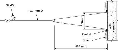
11.5 Spray test, following Walker et al. (2005).
In this test, the sample is sprayed over a period of 60 minutes or until the sample has completely eroded through. A jet of water projecting at 50 kPa from a standard nozzle is placed 470 from the sample. The exposed surface of the sample is a circle 150 in diameter. The maximum depth of erosion is measured after one hour of exposure and the sample is checked by eye to determine the extent of the penetration of moisture. Failure is judged to be when the maximum erosion thickness exceeds 60 or when moisture has penetrated to the back of the sample.
This test simulates two conditions of the erosion of earth walls due to rainfall: humidification (increasing the moisture content of the material, corresponding to a decrease in internal cohesion) and kinetic energy impinging on earth material (which will break the already weakened bonds of material particles). That is why this test is often used in practice (Walker et al., 2005; Heathcote, 2002). However, these authors also noticed that the conditions of this test are more severe than actual climatic conditions observed onsite. It is valid only for stabilised earth materials. Therefore, optimisation of test conditions: water pressure, distance between the jet and the sample, the acceptable thickness of erosion will be required for each climate zone. In addition, the dispersion of results is often very important (Thomson et al., 2008).
11.4.2 Drip test
This test was developed to provide a simple way for builders to determine soil suitability themselves. In this test, 100 of water is released via a wet cloth wick, which then falls 400 in height onto brick samples inclined at an angle of 27° from the horizontal (Fig. 11.6). This action is meant to simulate rain droplets. Frencham (1982) related the depth of pitting after the test to an Erodability index (Table 11.1).
Table 11.1
Scale of assessment for ‘drip test’
| Erodability index (EI) | Depth of pitting d (mm) | Note |
| 1 | 0 | Non-erosive |
| 2 | 0 < d < 5 | Slightly erosive |
| 3 | 5 < d < 10 | Erosive |
| 4 | d > 10 | Very erosive |
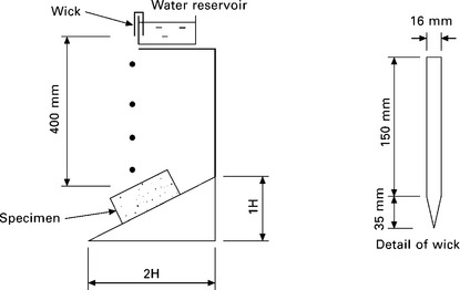
11.6 Drip test, following Heathcote (2002).
With kinetic energy of droplets and increasing water content in the material during the drip test, this simple test can be acceptable in areas where annual precipitation is around 500 . Its applications to areas of higher rainfall are not yet confirmed.
11.4.3 Wire brush test (ASTM D559, 1989)
In this test, earth is compacted in a 100-mm diameter mould to a depth of approximately 125 . After 7 days of storage, the samples are oven dried and weighed. They are then placed in water for 5 hours, oven dried and brushed with a firm wire brush (with a constant vertical pressure) to remove any materials loosened during the wetting-drying cycles. After 12 cycles of wetting and drying, they are oven dried and their final mass is recorded. The percentage loss in weight is calculated.
This test is similar to the ‘abrasion test’ which assesses the susceptibility of earth material to abrasion (Walker et al., 2005). This test was originally developed to test the durability of soil–cement mixtures used in road construction. However, the test has similar conditions to heavy driving rain on the surface of the earth walls: first, there is a moisture content increase in the material and then a ‘digging’ energy is applied to create erosion on the material surface. This is why several authors have considered the test suitable to test the durability of cement stabilised CEBs (Heathcote, 1995). Fitzmaurice (1958) has proposed the limits of weight loss for CEBs in the case of permanent buildings in urban areas: 5% in regions with annual rainfall greater than 500 ; 10% in regions with annual rainfall less than 500 .
11.4.4 Saturated to dry strength ratio
This test was developed to test stabilised CEBs. The specifications of this test are: a minimum compressive strength of 2 MPa in the ‘dry’ state and a minimum compressive strength of 1 MPa at the saturated state; plus a requirement that the ratio of saturated to ‘dry’ strength is not less than 0.5. It takes about 48 h for an earthen specimen soaked in water to be saturated.
This test is part of the family that uses the saturated compressive strength of the material to assess its durability, because if the material has sufficient strength in a saturated state, it will withstand the normal operating conditions of a building without a problem. However, several researchers have mentioned that this test is too severe and non-realistic compared to in situ conditions (Kerali and Thomas, 2004; Heathcote, 1995). According to the results of studies by Walker (1995), Krishnaiah and Suryanarayana (2008), Reddy and Kumar (2011) and our study at ENTPE on compressed earth blocks and stabilised rammed earth, many specimens that were stabilised at less than 4% by weight (by cement in these cases) could not meet the above criteria (Fig. 11.2).
Another criterion that should be used is that the compressive strength at saturated state must be greater than the maximum stress supported by the material.
11.4.5 Slake durability test
This test is usually used to test the durability of soft rocks (clayey rocks and mud-stones) (Fig. 11.7). Kerali and Thomas (2004) have proposed using this test to assess the durability of cement stabilised CEBs.
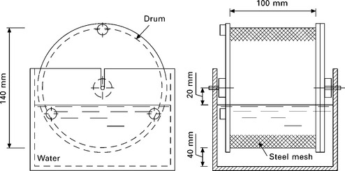
First, 30 × 30 × 30-mm samples are cut from cement stabilised CEBs. For each test, four to five prismatic samples per drum are placed so that both specimen-to-specimen and specimen-to-mesh contact is occurring. Samples of oven dried prisms are initially weighed (wi), and rotated at 20 turns per minute for 10 minutes in drums made of 2 steel mesh half immersed in tap water at 20°C.
A slake durability index is defined as the percentage of mass remaining after drum rotation:
where Wf is the final dry weight.
Following the classification proposed by Franklin and Chandra (1972), samples with SDI above 50% are considered ‘satisfactory’.
Following Kerali and Thomas (2004), the slake durability test gives results consistent with observations onsite. However, this test can only be applied to stabilised earth material. In addition, the preparation of 30 × 30 × 30-mm samples by cutting CEBs will certainly change the initial block characteristics.
11.4.6 Rainfall test
This test was proposed by Ogunye and Boussabaine (2002b) to test the durability of stabilised CEBs. The schema of this test is illustrated in Fig. 11.8.
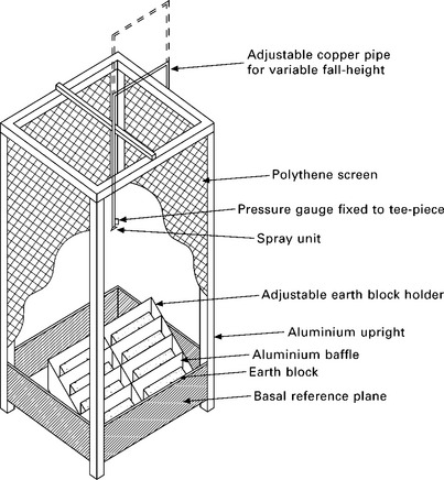
11.8 Schema of rainfall test, proposed by Ogunye and Boussabaine (2002b).
The distance between the nozzle and the basal reference plane is adjustable to permit variation in the fall-height of the drops thereby permitting variation of their energy at impact.
The (0.985 × 0.950 × 0.25 m) basal reference plane is fixed and inclined with a slope of 2.5° to permit free drainage to a 20-mm diameter copper outlet pipe. In this plane, there is an adjustable block holder (platform) on which samples are arranged for the exposure test. This (0.950 × 0.890 m) platform is pivoted and attached to a worm and screw mechanism that allows variable inclination of 15–45° to the spray water direction. This angle is based on the fact that rain always hits the building walls at an angle depending on the horizontal velocity component due to wind. The platform is partitioned into several parts by a 0.25-m height aluminium baffle to intercept soil splash and prevent possible interference with other samples. The samples are placed on a plate raised 3 cm above the level of the platform to avoid the possibility of water eroding the lower part of the sample.
In the study by ogunye and Boussabaine (2002b), the platform was inclined 30° to the spray water direction. With the aim of simulating rain in Nigeria, the authors left a pressure of 0.5 kg/cm2 and 2 m fall-height, corresponding to an intensity of 150 /h. The samples were exposed for 120 h, according to the average rainfall time in tropical countries. The weight of the lost material was determined after the test.
11.4.7 Stability in static water
Minke (2000) presents a test following the German standard (DIN 18952). A prismatic sample is immersed 5 cm deep into water and the time taken for the submerged part to disintegrate is measured. According to this standard, samples that disintegrated in less than 45 minutes are unsuitable for earth construction.
11.4.8 Freezing and thawing (ASTM D560)
The freezing and thawing test consists of placing a soil sample on an absorbent water-saturated material in a refrigerator at a temperature of − 23°C for a period of 24 h and then removing it. The sample is then thawed in a moist environment at a temperature of 21°C for a period of 23 h and then brushed. The freezing–thawing cycles are repeated and then the sample is dried in an oven to obtain a constant weight. This test is considered too severe for earth material (Guettala et al., 2006; Ogunye and Boussabaine, 2002a).
11.5 Surface coatings and finishes of earth structures
For modern stabilised walls, surface coatings are not always necessary, because the stabilised earth material can satisfy the conditions of durability without any coating and also the coating can detract from the appearance of the earth walls, which is aesthetically pleasing. However, in some cases, coating is still used such as the maintenance of existing walls or if occupants want to personalise their home.
The entry of moisture into an earthen wall is caused by rainfall, condensation, infiltration and adsorption from the surrounding ground and from general use of the building. Theoretically, a good coating would ensure full waterproofing and that external water cannot filter into the wall. However this solution is difficult to implement and requires very careful maintenance because any zone of weakness in the impervious layer can result in the concentration of moisture penetration in these regions, which lead to local areas of mechanical weakness in the wall (Bui and Morel, 2007; Hall and Djerbib 2006a).
For earthen walls, paint coatings often do not work well. A thin coating sticks well to earth but, over time, the paint coating develops cracks and peels off due to the differential thermal expansion of the earthen wall and the paint layer. Thus some portions of earthen wall are exposed in patches, facilitating water penetration into the wall. Due to the cracks in paint, the paint protection layer can be washed away by rain, which can lead to damage. Also, damage can occur due to accumulated water behind the paint layer. In a study by Bui and Morel (2007), the surface quality of the walls protected by paint was worse than the walls without any coating, which shows that paint protection is not appropriate for earthen media.
In general, for earthen walls, plaster is a better option than paint coating. With a permeable coating, water can penetrate through the coating but it stops after a few centimetres from the surface, because a saturated region is formed that provides a barrier to further water penetration (Hall and Djerbib, 2005a). This water is then evaporated in warmer or drier periods.
Plaster is composed of a granular skeleton, a binder and eventually of admixtures that improve its properties. The granular skeleton role is played by sands and silts, which are naturally present in earth, but generally in small amounts. The binder role can be played by clay or lime. Cement, is not recommended as a binder for plasters on earthen walls because a cement coating is usually impermeable to water vapour, which prevents the wall from ‘breathing’. There are three main types of coatings for earthen walls: earthen plasters, lime plasters and gypsum plasters.
The role played by a coating is different depending on whether it is an interior or an exterior coating. An exterior coating has to protect the wall from weathering and impacts. An interior coating must contribute to the thermal, acoustic and aesthetic comfort of the room. Since exterior coatings are exposed to weathering, the exterior coating should be done using lime plasters. Interior coatings are not exposed to weathering, so can be done using lime, earth or gypsum plasters.
11.5.1 Implementation of coatings
Plasters are usually implemented in three layers: a scratch coat, a brown coat and a finish coat. The scratch coat is the bounding layer of the coating on the wall. Its binder/sand ratio is high and it must be wet enough to ensure a good migration of binder towards the wall. It strengthens the wall and the sand brings roughness to its surface. The brown coat corrects irregularities in the wall surface. The finish coat, thinner and less rich in binder than the brown coat, brings an aesthetic finish. The stabilisation of earth plasters can take place in all layers or only in the finish coat.
Unlike standardised building materials, earthen wall and plaster materials show considerable variability. Depending on the constructive mode and the origin of the materials of the wall, a plaster formulation may or may not be suitable. For each site, plaster formulation has to be adapted to the wall. Thus plaster formulation validation can only be done by on site tests in conditions as close to as possible to those of real work. The different earth/sand or lime/sand batching, possibly supplemented with admixtures, are tested for their shrinkage and shear behaviour on the wall to be plastered. A series of two tests is proposed to validate coating formulations on given earthen walls (Hamard et al., 2013).
11.5.2 Shrinkage test
The shrinkage test of plasters on earthen walls consists of applying a 250 × 250-mm sample of brown coat of each formulation to be tested. After drying of the samples, when shrinkage is completed, it is possible to note the presence or absence of shrinkage cracks. Test results remains valid only if plaster is applied on a support in a state (brushing and humidification) similar to that of the test conditions.
11.5.3 Shear test
For earthen walls that consist of layers of earth (rammed earth, cob), elements of masonry (adobe, CEB) or of the filling of a timber-framed wall (wattle and daub), their heterogeneities must be taken into account in the testing. Therefore it is advisable to apply several samples testing different parts of the wall.
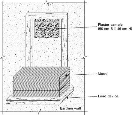
The purpose of the shear test for plasters on earthen walls is to ensure a sufficient bond between the plaster and the wall. The test consists of applying five samples of each plaster formulation to five different parts of the wall. Once dry, samples are submitted to a load of 2 kg. This ensures a safety coefficient greater than 10 since the thickest plasters are about 60 with a mass of 0.2 kg. This test must be carried out under conditions replicating those of real onsite implementation.
Preparation of samples
• Scrape and wet the wall as for the plaster
• Implement the scratch coat as for the plaster
• Apply, as for the plaster, five samples (or more) of 40 height, 50 width and 20 thickness. If the support is composed of different elements (mud blocks, adobe, layers of earth, etc.), at least two samples must be on an interface and at least two samples must be in the middle of an element, each sample testing a different element or a different interface,
• When samples are dry, it is possible to add a fine mortar layer to allow a good backing of the load device.
Test schedule
• First, place the load device on the upper part of the sample and be careful to minimise friction between the load device and the wall. Then, deposit the load of 2 kg on the load device and start the stopwatch (Fig. 11.9).
• If the sample does not fail after 30 s, we consider that it resists the load.
Validation of the formulations
• If the five samples resist the load, then the formulation is validated. If one or more of the five samples does not resist the load, then the formulation cannot be validated.
The shrinkage test eliminates formulations beyond a shrinkage threshold specific to the coating-wall combination, and the shear test eliminates formulations not offering sufficient resistance to traction and, therefore, sufficient shear strength, of coating-wall interface.
11.5.4 Wall preparation and weather conditions
Before coating an earthen wall it is advisable to let a full seasonal cycle pass, i.e. a year, to enable the wall to dry. For the same reason it is advisable to let a full seasonal cycle pass after the application of the brown coat to apply the finish coat.
Earthen walls must be properly prepared to receive a coating. They must be cleared of all non-consolidated elements to ensure a solid bond between the wall and the coating. They must be wetted to create a pool of water in the wall allowing a sufficient working time and a correct curing for the coating. Periods of heat and/or dry wind prevent proper wetting of the wall, they are therefore prohibited. During periods of freezing, the water released from the coating into the wall can cause damage. These periods are also not recommended.
11.6 Long-term performance testing of earth walls
11.6.1 Study by Guettala et al.
To assess the suitability of laboratory tests for the earth material durability, Guettala et al. (2006) have tested in two different ways on similar samples: laboratory tests and field tests. For the laboratory tests, Saturated to dry strength test, Spray test, Capillary absorption test and Freezing–thawing test were carried out on four CEB types with different compositions. For the field tests eight walls were built with the same CEBs as for the laboratory tests. These walls were exposed to real climatic conditions for 48 months (Fig. 11.10). Annual precipitation on the site was about 120 . Although quantitative measures on walls were still lacking, this study showed that all the laboratory tests mentioned above were too severe compared to what happens onsite for a dry climate.
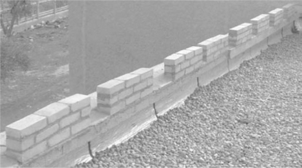
11.10 Walls exposed to real climatic conditions in the study by Guettala et al. (2006).
11.6.2 Study by Bui et al.
Bui et al. (2009) presented a study on the durability of different types of stabilised and unstabilised rammed earth walls. These rammed earth walls were constructed and exposed to natural weathering for 20 years, in a wet continental climate (Fig. 11.11). The erosion of the rammed earth walls was measured using stereo-photogrammetry. The result showed that the mean erosion depth of the studied walls was about 2 (0.5% wall thickness) in the case of a rammed earth wall stabilised with 5% by dry weight of hydraulic lime, and about 6.4 (1.6% wall thickness) in the case of unstabilised rammed earth walls.
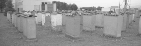
11.11 General view from the south of the in situ walls in study by Bui et al. (2009a).
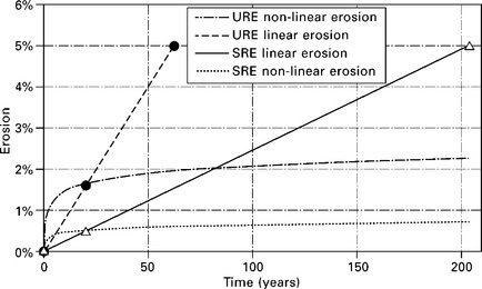
In general, the erosion of a rammed earth wall is not a linear function of time. Initially, the wall shows more erosion on the surface, and over time the erosion stabilises (Fig. 11.12 non-linear erosion). This non-linearity is due to the loss of compaction energy caused by friction on the formwork - the earth which is in contact with the formwork is less compacted and therefore more eroded. However, it is currently impossible to estimate exactly the lifetime of these walls using nonlinear functions. That is why two linear functions of time were used to assess the durability of unstabilised rammed earth (URE) and stabilised rammed earth (SRE) walls (Fig. 11.12). For URE walls, 63 years should be required before these walls are eroded to 5% thickness. For SRE walls, the time should be 204 years. The non-linear erosion curves in this figure are only examples of the possible non-linear behaviour of erosion that is often observed empirically in reality, but there are still no scientific data giving an exact function. However, because erosion with time is not linear, the lifetime of these walls may be much longer than 63 and 204 years, respectively, for unstabilised and stabilised rammed earth walls. This shows again that laboratory tests are generally too tough for a moderate climate.
11.7 Future trends and conclusions
For modern earthen constructions, the walls are often stabilised and are not coated, because the coating can detract from the appearance of the earth walls, which is aesthetically interesting. So, the stabilised earthen material itself must meet the durability requirements.
Spray tests are interesting because of their simplicity. However, this test simulates ‘extreme’ conditions and therefore gives harsh conclusions about the durability of earth material tested. Calibration of this test is required for each climatic zone.
The ‘drip test’ is suitable for areas where precipitation is moderate, while the ‘wire brush test’, the ‘slake durability test’ and the ‘freeze–thaw test’ are not particularly suitable to assess the durability of earth material in areas with moderate precipitation. They may be better suited to the ‘extreme’ climatic zones, for example areas there is the current risk of flooding.
The ‘rainfall test’ presents several advantages due to its complexity but this point is also a disadvantage for applying the test in practice. Also, the test needs to be calibrated for each climatic zone.
The ‘saturated to dry strength test’ is not a good indicator for unstabilised materials or materials stabilised at low dose (< 2% by weight). However it is simple and can be used for stabilised earth materials that suffer severe conditions such as high precipitation, flooding, retaining walls. For unstabilised materials or materials stabilised at low dose, the ‘stability in static water test’ can be applied.
In situ long-term testing gives valuable data because all factors depending on climate and time are combined. However, these tests are very expensive and very long. In addition, data are only valid for the climatic zone studied; it is difficult to ‘extrapolate’ for other climatic zones.
In the near future, pressure on sustainability of building will increase and, for example, embodied energy of construction will be taken in account rigorously in regulations as has happened recently with thermal building behaviour. In this context, there are three directions of development with regard to sustainability of earthen constructions.
Development of architectural design able to build with earth dug onsite without any admixtures (unstabilised), such as thick bearing walls or non-bearing walls. This would allow the use and reuse of earthen materials without causing pollution.
The second trend is the use of coatings to protect walls. This can provide acoustic and thermal qualities, and protection against moisture, while minimising the amount of high embodied energy material used. The use of coatings will be increased by establishing design guidance to implement mortars with local or able materials.
Finally, the use of low embodied energy stabilisers in walls or in coatings; for example, of vegetable origins (fibres or biopolymers), may be interesting because it may increase the durability of some earthen materials.
11.8 Acknowledgements
The authors wish to thank Ali Mesbah and Myriam Olivier from ENTPE, for all the research done since 1982 on engineering assessment of earthen architecture. The authors also wish to thank the professional, in earth construction at ‘Réseau Ecobâtir’, in particular Alain Marcom and Nicolas Meunier, for sharing their valuable know-how.
11.9 Sources of further information
Bui Q B, Morel J C (2009). ‘Assessing the anisotropy of rammed earth’, Construction and Building Materials, 23: 3005–3011.
Bui Q B, Hans S, Morel J C, Meunier N (2009b). ‘Compression behaviour of nonindustrial materials in civil engineering by three scale experiments: the case of rammed earth’, Materials and Structures, 42, 8: 1101–1116.
Hakimi A, Ouissi H, El Korbi M, Yamani N (1998). ‘Un test d’humidification-séchage pour les blocs de terre comprimée et stabilisée au ciment’, Materials and Structures, 31, 20–26.
Gelard D (2005) ‘ Identification et caractérisation de la cohésion interne du matériau terre dans ses conditions naturelles de conservation’. PhD thesis, Institut National Polytechnique de Grenoble.
Guelberth S R, Chiras D (2003) ‘The Natural Plaster Book – Earth, Lime and Gypsum Plasters for Natural Homes’, New Society Publishers
Hall M, Djerbib Y (2006b) ‘Moisture ingress in rammed earth: Part 3 – sorptivity, surface receptiveness and surface inflow velocity’, Construction and Building Materials, 20, 6: 384–395.
Jaquin PA, Augarde CE, Gallipoli D, Toll DG (2009) ‘The strength of rammed earth materials’, Géotechnique, 59, 5: 487–490.
Keefe L (2005) Earth Building – Methods and Materials, Repair and Conservation, Taylor and Francis, 197 pp.
Kenmogné E (1993) ‘Dégradation des matériaux de construction: contribution à l’étude de la faisabilité des terres argileuses en construction’, PhD thesis, Université Joseph Fourier.
McHenry PG (1984) Adobe and Rammed Earth Buildings – Design and Construction, The University of Arizona Press, 217pp.
Morel J C, Mesbah A, Oggero M, Walker P (2001) ‘Building houses with local materials: means to drastically reduce the environmental impact of construction’, Building and Environment, 36, 1119–1126.
Olivier, M (1994) ‘Le matériau terre, compactage, comportement, application aux structures en blocs de terre’, PhD thesis, INSA de Lyon.
Rubaub M, Chevalier B (1986) ‘Etude de différents systèmes de protection superficielle du matériau ‘terre’ utilisé pour la construction – Expérimentation en vieillissement naturel sur murets au CSTB’, for Centre Scientifique et Technique du Bâtiment.
Standards New Zealand (1998) NZS 4298:1998, Materials and Workmanship for Earth Buildings, Standards New Zealand, Wellington.
Taylor P, Luther MB (2004) ‘Evaluating rammed earth walls: a case study’, Solar Energy, 76, 79–84.
11.10 References
ACI 210R-93, Erosion of Concrete in Hydraulic Structures, 1998. [24pp].
ASTM D559 – 03, Standard test methods for wetting and drying compacted soil-cement mixtures, 1989.
ASTM D560, Standard test methods for freezing and thawing compacted soil-cement mixtures, 2003.
Bui, Q.B., Morel, J.C. Durability of rammed earth walls exposed for 20 years of natural weathering. International Symposium on Earthen Structures, Bangalore, August 2007. 2007; 113–120.
Bui, Q.B., Morel, J.C., Reddy, B.V.V., Ghayad, W. Durability of rammed earth walls exposed for 20 years to natural weathering. Building and Environment. 2009; 44:912–919.
Fitzmaurice, R. Manual on Stabilised Soil Construction for Housing. New York: Technical Assistance Program, United Nations; 1958.
Franklin, J.A., Chandra, R. The slake durability test. International Journal of Rock Mechanics and Mining Sciences. 1972; 9:325–341.
Frencham, G.J. The performance of earth buildings. Geelong: Deakin University; 1982.
Grossein, O., Modélisation et simulation numérique des transferts couples d’eau, de chaleur et de solutes dans le patrimoine architectural en terre, en relation avec sa dégradation PhD thesis. Université Joseph Fourrier, 2009. [218pp].
Guettala, A., Abibsi, A., Houari, H. Durability study of stabilized earth concrete under both laboratory and climatic conditions exposure. Construction and Building Materials. 2006; 20:119–127.
Hall, M., Djerbib, Y. Moisture ingress in rammed earth: Part 1 – the effect of soil particle-size distribution on the rate of capillary suction. Construction and Building Materials. 2004; 18:269–280.
Hall, M., Djerbib, Y. Moisture ingress in rammed earth: Part 2 – the effect of soil particle-size distribution on the absorption of static pressure-driven water. Construction and Building Materials. 2006; 20(6):374–383.
Hamard, E., More, J.C., Salgado, F., Marcom, A., Meunier, N., A procedure to assess suitability of plaster to protect vernacular earthern architecture to be published in Journal of Cultural Heritage, 2013.
Heathcote, K.A. Durability of earthwall buildings. Construction and Building Materials. 1995; 9(3):185–189.
Heathcote, K.A., An investigation into the erodibility of earth wall units Doctor of philosophy thesis. University of Sydney, 2002.
Kerali, A.G., Thomas, T.H. Simple durability test for cement stabilized blocks. Building Research and Information. 2004; 32(2):140–145.
Killip, I.R., Cheetham, D.W. The prevention of rain penetration through external walls and joints by means of pressure equalization. Building and Environment. 1984; 19:81–91.
Krishnaiah, S., Suryanarayana, R.P., Effect of clay on soil cement blocks. 12th IACMAG, Goa, India. 2008:4362–4368.
Minke, G.Earth Construction Handbook - The Building Material Earth in Modern Architecture. WITpress, 2000. [206pp].
Morton, T., Buckman, J. Traditional cob wall: response to flooding. Structural Survey. 2008; 4:302–321.
Ogunye, F.O., Boussabaine, H. Diagnosis of assessment methods for weatherability of stabilised compressed soil blocks. Construction and Building Materials. 2002; 16:163–172.
Ogunye, F.O., Boussabaine, H. Development of a rainfall test rig as an aid in soil block weathering assessment. Construction and Building Materials. 2002; 16:173–180.
Reddy, B.V.V., Kumar, P.P. Cement stabilized rammed earth - Part B: compressive strength and elastic properties. Materials and Structures. 2011; 44(3):695–707.
Thomson, A., Pope, D., Walker, P., Erosion characteristics of rammed earth. Kerpic08 – Learning from Earthen Architecture in Climate Change International Conference, Northern Cyrus, 2008.
Walker, P.J. Strength, durability and shrinkage characteristics of cement stabilised soil blocks. Cement and Concrete Composites. 1995; 17:301–310.
Walker, P., Keable, R., Martin, J., Maniatidis, V. Rammed Earth : Design and Construction Guidelines. BRE Bookshop; 2005.