Stabilised soil blocks for structural masonry in earth construction
Abstract:
Stabilised soil blocks (SSBs) are energy efficient and low embodied carbon alternative materials for structural masonry. there is an upsurge of interest among building professionals in utilising low embodied carbon materials. This chapter deals with various aspects of SSBs applicable to structural masonry. A brief outline of soil classification and developments in SSB technology is provided. different methods of soil stabilisation and production techniques for SSBs are discussed in detail. The influence of soil composition on SSB characteristics and optimum soil grading for the production of SSBs are discussed. the role of block density, moulding moisture content and stabilisers on various SSB characteristics including durability aspects is illustrated. The chapter ends with a discussion of the behaviour of SSB masonry, guidelines for SSB masonry design and some short case studies.
13.1 Introduction
Soil has been the basic construction material ever since human civilisation learned to build structures for habitation. earthen buildings can be seen across the world and earth construction techniques are still in vogue in many parts of the globe. Cob, adobe, rammed earth, and wattle and daub represent just some of the traditional soil-based construction techniques used for earthen buildings. The use of soil for wall construction has distinct advantages, such as the readily available local material, lower cost, and being recyclable and environment friendly. Also, earthen buildings provide better thermal comfort than buildings made from other conventional materials. Some of the major drawbacks of mud walls are the larger wall thickness, loss of strength due to saturation, issues relating to durability and erosion due to rain impact. these disadvantages can be minimised or eliminated by the use of stabilised soil products/techniques for the walls.
Burnt clay brick walls are highly durable and are most commonly employed for the construction of load-bearing buildings. Soils with a sufficient clay fraction are essential for the manufacture of burnt clay bricks. Processed soil is shaped into a brick and then fired at 800–1000 °C for manufacturing. The clay minerals in the fertile soil are permanently transformed into other types of mineral products during the firing process. Retrieving the original soil clay minerals from the burnt clay bricks is not possible. Burnt clay bricks are considered energy intensive and are not eco-friendly because of the destruction of fertile clay minerals. The embodied energy content of masonry using burnt clay bricks is about 2200 MJ/m3, whereas for masonry using alternative materials such as cement-stabilised soil blocks (CSSBs), the embodied energy is in the range of 550–700 MJ/m3 (Venkatarama Reddy, 2008b and 2009). There is clearly a need for an energy efficient, economical and eco-friendly technology to satisfy the ever-increasing demand for the construction of new buildings. SSBs represent one such alternative solution for the construction of structural walls in buildings. Manufacture of SSBs involves utilisation of the locally available soils in producing durable and eco-friendly materials for the construction of walls. The concept of SSBs for masonry was originated in the early 1940s with the introduction of hand-moulded SSBs. Later, machines came into the picture and the technology is now well matured and commercially exploited for the construction of load-bearing masonry structures.
13.1.1 Soil classification for stabilised soil blocks (SSBs)
Soil is the basic material for the manufacture of SSBs. It is therefore essential to understand the types of soils and methods of selecting the correct stabiliser additives. There are several soil classification systems based on properties such as grain size distribution, Atterberg’s limits, etc. the basic purpose of such soil classifications is to facilitate an understanding of the properties and behaviour of a soil to be used for a specific engineering application (soil classification systems were dealt with in detail in an earlier chapter of this book). the type and percentage of clay mineral present in a soil dictates the selection of the stabilising additive needed for SSB production. Large varieties of clay minerals exist in nature. Kaolinite, illite and montmorillonite are the most commonly occurring clay minerals in soils. For SSB purposes, soils can be broadly classified into two categories: expansive and less expansive soils. Expansive soils are those with excessive swelling clay minerals such as montmorillonite. The presence of expansive clay minerals in soils can cause excessive swelling when the soil comes into contact with water and also shrinkage when it undergoes drying. Using such soils for SSB production demands the use of a sufficient quantity of lime (calcium hydroxide). Lime reacts with expansive clay minerals and forms cementitious hydrates of calcium–silicate, calcium–aluminates, etc., responsible for the development of strength in lime-stabilised SSBs. Less expansive soils, such as those containing minerals such as kaolinite and illite, do not swell and shrink as much as expansive soils. Cement stabilisation is best suited for less expansive soils and for the production of SSBs using such soils. Identification of a soil with respect to its swelling and shrinking characteristics is essential when selecting a suitable stabiliser additive for the production of SSBs.
13.1.2 Developments in stabilised soil block technology
Stabilised soils were successfully used for the construction of road and pavement sub-bases from 1920 to 1950 (Chaston, 1952; Lambe, 1962). Use of compacted stabilised soil (using cement/lime binders) for building construction can be seen after the 1940s. Initially, stabilised soils for building construction started with the concept of rammed earth walls. Later, stabilised soils were used to manufacture hand-compacted blocks, for use in the construction of load-bearing masonry. In the period from 1940 to 1950, and prior to the invention of machines for the purpose of compacted soil block production, hand-compacted SSBs were used for the construction of masonry walls. Cement-stabilised hand-compacted blocks were used for the construction of 260 houses in Bangalore during 1949 (Madhavan and Narasinga Rao, 1949), when wooden moulds were used to manufacture the blocks; load-bearing masonry walls (250 mm thick) were built with blocks containing 4–5% cement in mud mortar and the buildings had reinforced concrete flat slab roofs. Another Indian example from 1950–1951 was the construction of residential colonies in the northern Indian regions to house the workers employed in hydroelectric projects and dams during the period (Mitra, 1951).
The CINVA-RAM press, developed in 1952 by Paul Ramirez, was the first (manual) machine to produce compacted soil blocks for building construction. Its development led to the concept of machine-pressed SSBs. A number of groups in Europe, Australia and in other countries started working on SSB technology and began producing machines, and various buildings using SSB technology and employing machine-pressed SSBs were built in Columbia, Chile, Venezuela and Brazil during the early 1960s (UN, 1964). Social housing projects involving large numbers of houses of up to three-storey construction were built using cement SSBs and rammed earth in Isle D’Abeau, near Grenoble in France, during the early 1980s. Reports and other documents on stabilised earth construction by Middleton (1952), the Department of Housing and Urban Development (1955) and Fitzmaurice (1958) represent the beginning of compacted SSBs for building construction. Mukerji (1986) published a survey of soil block making machines developed in several countries across the world and a large number of machines (manual, semi-and fully automatic) are still commercially available in the market.
Investigations into SSB technology can be grouped into two major areas: (i) manufacturing and characterisation of SSB properties; and (ii) the behaviour of SSB masonry under compression, tension and shear. Cement and lime represent the most commonly used stabilisers for SSB production and hence discussions here have a bias towards cement and lime SSBs.
A good understanding of the various aspects of confined static compaction of soils is needed for the design and development of machines to manufacture compacted SSBs. The force/energy needed for the compaction of a soil block, the moisture, density and energy relationships and optimum moisture content are some of the issues investigated by Olivier (1994), Venkatarama Reddy (1983, 1991), and Venkatarama Reddy and Jagadish (1993). Production techniques, strength, dimensional stability, durability and stress–strain characteristics are some of the major parameters explored for cement-stabilised and lime SSBs. SSB technology has been addressed by Fitzmaurice (1958), Spence (1975), Lunt (1980), Middleton (1952), Olivier and Mesbah (1987), Heathcote (1991, 1995), Houben and Guillaud (2003), Venkatarama Reddy and Jagadish (1995), Walker and Stace (1997), Walker et al. (2000), Walker (2004), Venkatarama Reddy and Walker (2005), Venkatarama Reddy and Gupta (2005a), Venkatarama Reddy et al. (2007a), Venkatarama Reddy (2007), and in many other publications. Studies of masonry using SSBs have been undertaken by Venkatarama Reddy and Jagadish (1989), Shrinivasa Rao et al. (1995), Walker (1999), Walker (2004), Venkatarama Reddy and Gupta (2006, 2008), Venkatarama Reddy and Vyas (2008) and Venkatarama Reddy et al. (2009) amongst others.
13.2 Soil stabilisation techniques
Soil is used for the construction of roads, structural walls, masonry mortars, floors, roofs, etc. Natural soil has certain distinct characteristics or properties such as strength, plasticity, swelling, shrinkage, etc. These properties are controlled by its grain size distribution, and by the type and quantity of clay minerals present. Some of these properties may have to be altered in order to make the natural soil suitable for any specific construction. The alteration of existing soil properties to meet specific engineering requirements can be termed ‘soil stabilisation’.
In SSBs, the bulk of material used is soil. Important requirements for an SSB masonry wall are adequate strength, resistance to moisture ingress, volume stability and durability, i.e. resistance to rain erosion and mechanical damage. Very rarely, the natural soils in their native state can impart the above requirements to the SSBs being produced. Normally, however, the natural soil has to be stabilised in order to make it suitable for the production of SSBs. Soil stabilisation techniques can be grouped into three broad categories: (i) mechanical stabilisation; (ii) stabilisation by compaction; and (iii) stabilisation by additives.
13.2.1 Mechanical stabilisation
Mechanical stabilisation is an inexpensive method of stabilising a soil, in which two or more soils with different characteristics are mixed, or sometimes inert materials such as sand and gravel are mixed in to get the desired grading for a soil. Generally, soils have either an excess clay fraction or are deficient in the sand fraction. In order to make them suitable for earth wall construction, it is essential to either dilute the soil by the addition of sand/gravel or mix it with another soil of different composition. Either way, the natural soil properties are altered to make them suitable for the production of SSBs.
13.2.2 Stabilisation by compaction
Compaction is the best-known soil stabilisation technique used to improve strength and reduce porosity. Here, the soil in its loose state is brought to a dense state by supplying compaction energy. There are two types of soil compaction techniques: static and dynamic compaction. Improvement in strength, reduction in porosity and other properties depend upon the soil composition, moulding water content and the compaction energy supplied.
13.2.3 Stabilisation by additives
In this type of stabilisation, both organic and inorganic additives in either solid or liquid form are added to alter the soil properties. Additives such as cement, lime, bitumen, polymers, certain salts, organic binders, organic and inorganic fibres are used. Selection of the type of additive depends upon the kind of alteration expected in the soil property and the ultimate product/application. For example, if control of shrinkage cracks on drying is required, the use of fibres is recommended; if there is a need to control the swelling of the soil, lime is added; if an improvement in the erosion characteristics of the earth blocks is required, bitumen can be added.
In the majority of soil stabilisation processes, more than one of the above-mentioned methods is adopted. In the case of SSBs, all three methods of stabilisation mentioned above are used. As mentioned previously, cement and lime are the most commonly used additives for the production of SSBs.
13.2.4 Cement stabilisation
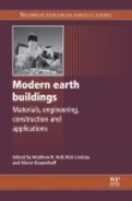
Cement stabilisation is ideal for coarse-grained and gravely soils, and is used to improve strength (especially in saturated condition), resistance against rain erosion and mechanical damage of the SSBs. the principle involved in cement stabilisation is illustrated opposite.
The major factors affecting cement-stabilised soils include soil composition, percentage of cement, degree of compaction achieved for the product, and the curing period and curing temperature. The strength of cement SSBs increases with the increase in cement content, density, curing period and curing temperature.
13.2.5 Lime stabilisation
Lime used for construction can be classified as hydraulic lime and non-hydraulic (or fat) lime. Hydraulic lime can set and harden in the presence of water, whereas fat lime derives its strength from a reaction with a pozzolanic material or through carbonation. Hydrated lime is usually used for lime stabilisation.
Lime stabilisation techniques are generally adopted for clayey soils, in order to control swelling and shrinkage. When lime is mixed with the soil, the clay minerals present in the soil react with the lime. These lime–clay reactions lead to the formation of a water insoluble gel of silicate and silicate–aluminates, and (with time) this gel finally crystallises into hydrates of calcium silicate, calcium aluminates, etc. The cementing agents formed in lime–clay reactions are similar to those formed during Portland cement hydration. The cementitious gel formed coats the soil particles and establishes bonds. The pace of lime–clay reactions and formation of cementitious gel is slow. These reactions take place continuously, even in the presence of just a little moisture in the surrounding atmosphere.
With reference to stabilised soil based building products, it is difficult to exploit the lime stabilisation technique mainly because of the slow pace at which the lime–clay reactions take place and because of the insufficient quantity of binding material formed in such reactions to derive meaningful strength for the SSB to be used in structural applications. Lime stabilisation is a must while manufacturing SSBs using soils containing expansive clay minerals such as montmorillonite, in order to control the swelling and shrinkage problems associated with such soils. Lime–clay reactions can be accelerated by raising the curing temperature. For example, it is possible to achieve 3 months’ ambient temperature curing results in less than 24 hours of curing at 80 °C (Venkatarama Reddy and Jagadish, 1984; Venkatarama Reddy and Lokras, 1998; Venkatarama Reddy and Hubli, 2002). Steam curing methods can be adopted for such purposes but result in additional cost and energy expenditure.
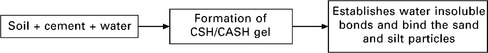
13.3 Production of stabilised soil blocks (SSBs)
Stabilised mud blocks, or stabilised compressed earth blocks are other names for stabilised soil blocks (SSBs). Processed soil that is mixed with stabiliser and water compacted into a dense block (Fig. 13.2) can be termed an SSB. Compaction is carried out at optimum moisture content (OMC) (though not necessarily at Standard Proctor OMC) generally using a machine. The blocks produced in this way are cured and then used for masonry construction.
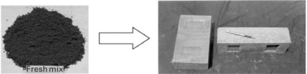
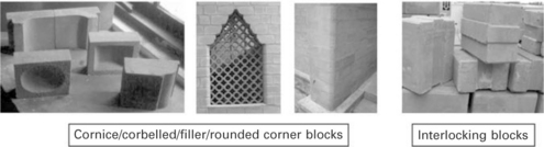
The characteristics of SSBs greatly depend on the clay fraction of the soil, block density and stabiliser content. Different types of SSB can be manufactured using different stabilisers and geometric configurations. Figure 13.3 illustrates the different types of SSB, whilst typical pictures of some of these SSBs are displayed in Fig. 13.4. Blocks of any desired shape and size can be manufactured using small attachments to the machine mould. SSB blocks are manufactured using machines employing a static compaction process. Block thickness in such a compaction process should be restricted to less than 100 mm in order to avoid stratification of block density across the thickness of the block.
SSBs are produced by a process, involving four critical steps: (i) soil selection; (ii) soil processing; (iii) pressing or compacting of the block; and (iv) curing.
13.3.1 Soil selection
Soils contain particles of different sizes such as gravel, sand, silt and clay minerals. Generally, soil is sieved through a 5-mm sieve, thus eliminating the gravel portion. Sand and silt particles are inert whereas clay is a mineral with a lot of affinity for water. Clay particles swell on absorption of water and shrink on drying; the amount of swelling and shrinkage is dependent upon the type and quantity of clay mineral present in the soil. Plasticity, shrinkage and strength, etc. of a soil are controlled by the quantity and type of clay minerals present.
Soils containing less expansive clay minerals (such as kaolinite) can be used for SSBs using Portland cement as a binder. Coarse-grained sandy soils containing predominantly non-expansive clay minerals are ideally suited for the production of cement-stabilised blocks. Soils containing an excessive silt fraction can lead to SSBs with very low green strength for handling during the block manufacturing process. In such situations it is advisable to add some coarse gravel or sand fraction to the soil. Acidic soils generally require the addition of hydrated lime to neutralise the acidity, as well as the use of Portland cement. Organic soils and soils containing sulfates are generally not suitable for stabilisation using cement/lime alone. Such soils require accelerating agents other than lime and cement. Expansive soils need lime to stabilise their swell–shrink properties and hence the use of lime is essential for producing SSBs from them. It is mandatory to test the cured blocks for strength and durability characteristics.
13.3.2 Soil processing
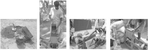
Soil processing involves different activities such as crushing/powdering of excavated soil, sieving, mixing with the sand and stabilisers in dry state, and then mixing with water. These processes bring the partially saturated mixture to a state ready for compaction in a machine. Generally, excavated soils contain lumps and the size of the lumps (in air dried state) mainly depends on the type and quantity of clay mineral present in the soil. Soil lumps have to be crushed and sieved (using a 4–5-mm sieve) in order to blend the natural soil with sand and stabilisers (such as cement or lime). Sieved soil is effective for arriving at a uniform mixture and better distribution of sand and stabilisers. Figure 13.5(a) shows a manually operated rotary sieve.
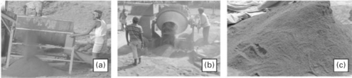
As we have already seen, natural soils in their original composition are rarely suitable for the production of SSBs. Hence, in the majority of cases the natural soils are blended with sand or equivalent inert materials such that the resulting mixture is suitable for SSB production. Basically, sand is used to modify the natural soil composition. For example a natural soil containing 30% clay can be reconstituted by mixing with sand in the ratio of 1:1 (soil to sand, by weight) such that the resulting mixture contains 15% clay, which may be the requirement for the production of SSBs with cement stabilisation. Soil and sand are generally mixed in a dry state. Dry mixing can be carried out in a rotating drum type of mixer (Fig. 13.5)(b). Mixing of soil and sand can also be done manually, where thin alternate layers of soil and sand are spread and mixed with a spade. Generally, mixing of powdery binders such as cement or lime with soil has to be carried out in a dry state. It can be performed either by using a mechanical mixer or manually. A mechanical mixer is more efficient in obtaining a uniform mixture. Adding the correct amount of moisture and mixing it uniformly with the soil–stabiliser mixture is a very important operation in the SSB production process. Here the soil is mixed with an optimum quantity of water (though not necessarily Standard Proctor OMC). this can also be carried out either manually or using a drum type mixer. In the manual process, the soil is spread into a thin layer (100–150 mm) and then water is sprinkled onto the layer. The wetted layer is mixed using a spade until a uniform mixture is ascertained. The mixing can also be carried out in a drum type or pan type mixer. The soil, sand, stabiliser and water mixture is brought to a semi-dry state. The partially saturated mixture (Fig. 13.5(c)) is then compacted into a high density block. The water content used in such mixes will be in the range of 10–14%.
13.3.3 Pressing or compacting the block
Processed soil in a partially saturated state is used for the manufacture of SSBs employing a static compaction process, which involves confined compaction of the wetted mixture in a mould using a piston, either from one side or from both sides, in order to densify the loose soil mix into a block. The compaction energy supplied is not a fixed value and depends upon the soil composition, moisture content and target density, and therefore the conventional standard Proctor density–moisture relationships have no relevance to the static compaction process employed in the production of SSBs using a machine. Various stages involved in the static compaction process employed in the production of SSBs are illustrated in Fig. 13.6.
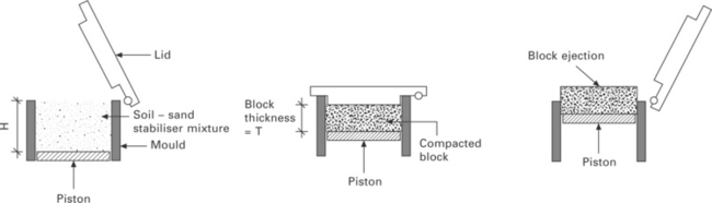
13.6 Various stages in the static compaction process (L–R): (a) mould filled with processed mix, (b) compaction through lid closure and piston movement, (c) ejecting a compacted block.
The dry density of the compacted soil mass is an indication of the degree of compaction. Compaction curves for static compaction and dynamic compaction, such as the standard Proctor test, are shown in Fig. 13.7. In the Standard Proctor test, the peak density and corresponding moisture content are termed maximum dry density (MDD) and optimum moisture content (OMC), respectively. Moulding moisture content, energy supplied (or compaction effort) and soil composition all control the MDD and OMC values. Higher compaction effort leads to a higher value of MDD and lower OMC. In the Standard Proctor test, the energy supplied to the soil specimen is fixed.
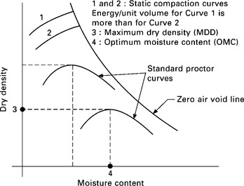
In the static compaction process, the concepts of MDD and OMC do not arise, since the energy supplied is not constant here. While employing the static compaction process, it is preferable to achieve as much dry density as possible by using a suitable moisture content. Static compaction curves for constant energy input can be generated indirectly through energy–density and energy–moisture relationships (Venkatarama Reddy and Jagadish, 1993); such static compaction curves are shown in Fig. 13.7.
The dry density of a block has a controlling influence on the strength of the SSB and hence block weight has to be controlled to control dry density. The block compaction process involves: (i) weighing the wetted mix of soil; (ii) feeding it into the machine mould; (iii) closing the lid and compaction; (iv) ejecting the block; and (v) stacking. Figure 13.8 illustrates the various steps involved in block production employing a manual process (a time and motion study conducted by Venkatarama Reddy (1983) showed that the rate of block production using manual processes is not controlled by the weigh batching activity).
13.3.4 Curing
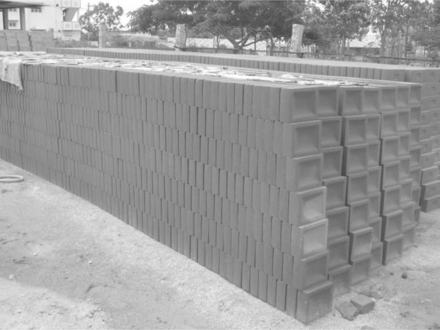
Cement SSBs need moisture for the development of hydration products responsible for establishing water insoluble bonds, and therefore they require curing. Such blocks are stacked one above the other and water is sprinkled three to four times daily for four weeks (Fig. 13.9). After completion of curing, the blocks are allowed to dry in the stack before being used for construction. In order to reduce the curing period and to achieve higher strengths, steam curing at low temperatures (80 °C) is often undertaken, at atmospheric pressure for 10–12 hours. Lime–clay reactions are slow at ambient temperatures and hence need a longer curing period to achieve meaningful strengths; these blocks can also be cured using steam curing techniques (see Venkatarama Reddy and Hubli (2002) for more information on steam curing).
13.3.5 Machine requirements for block production
Manually operated, semi-automatic or fully automatic machines can be employed for the compaction and manufacture of SSBs. All these machines employ a static compaction process (the various steps of which are illustrated in Fig. 13.6) to achieve the requisite dry density for a block. The compaction ratio of the machines should not be less than 1.70. The compaction ratio = (H)/(T), where H is the height of loosely filled mix in the machine mould (Fig. 13.6(a)) and T is the block thickness, which should be restricted to 100 mm or less. Block thickness in excess of 100 mm can lead to a variation in the density of the block across its thickness when the static compaction process is employed (Venkatarama Reddy, 1991), and thus production of thicker block results in poor compaction in the top portion and better compaction in the bottom portion (from where the maximum piston movement takes place).
13.4 Characteristics of stabilised soil blocks (SSBs)
Strength, durability, water absorption, development of bond with the mortar and stress–strain relationships are some of the important SSB characteristics needing to be considered when they are used for load bearing masonry. The major factors influencing theses characteristics are: (a) composition of the soil–sand mixture; (b) density of the block; and (c) the type and quantity of stabiliser.
13.4.1 Influence of soil grading and composition on the strength of stabilised soil blocks (SSBs)
The grain size distribution of the soil and the clay minerals present in the mix play a significant role in the strength of SSBs. The type and quantity of clay minerals in the mix can dictate and control the type and quantity of stabiliser required to achieve a particular strength of SSB. The compressive strength of an SSB is sensitive to the moisture content of the specimen at the time of the test: saturated or dry conditions are the two extremes under which the compressive strength of an SSB can be measured. Compressive strength measured under saturated conditions is termed wet compressive strength, whilst strength measured in totally dry condition is designated dry compressive strength. The ratio between wet and dry compressive strengths can range between 0.20 and 0.55 (Venkatarama Reddy and Gupta, 2005b; Venkatarama Reddy et al., 2007a; Walker and Stace, 1997; Venkatarama Reddy and Walker, 2005) depending on factors such as block density, percentage of clay fraction in the mix, type of clay mineral present in the soil, stabiliser content, etc.
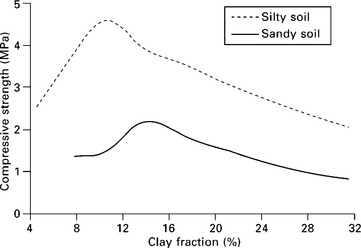
Soils with predominantly non-expansive clay minerals are ideal for cement stabilisation. The role of the clay fraction of the soil–sand mix on strength of CSSBs is illustrated in Fig. 13.10. The curves in Fig. 13.10 were generated for cement-stabilised compacted cylindrical specimens with constant dry density and similar moulding moisture content at each of the clay fractions in the mix. There is an optimum clay content yielding maximum strength for CSSBs (Venkatarama reddy et al., 2007a), optimum clay content being in the range of 10–15% (close to 15% for coarse-grained sandy soils and in the vicinity of 10% for fine-grained silty soils).
13.4.2 Density and strength relationships
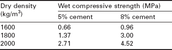
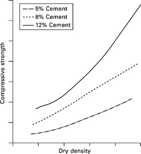
The density of an SSB has significant influence on compressive strength. The compressive strength of a compacted cement-stabilised soil mix increases with the increase in density irrespective of cement content and moulding moisture content. Some of the typical strength–density relationships are shown in Fig. 13.11 for different cement contents. Compressive strength is very sensitive to variations in density, and marginal increase in density leads to a large increase in strength. Typical values of strength and density are given in Table 13.1 for compacted cement soil specimens with 5% and 8% cement (Prasanna Kumar, 2010), where it can be seen, for example, that a 10% increase in dry density from 1600 kg/m3 leads to a 200% increase in strength for both 5% and 8% cement. Venkatarama Reddy and Walker (2005) reported a sharp increase in strength as density increases. Increase in strength due to an increase in dry density can be attributed to a reduction in the porosity (hence a closer contact of the particles) of the compacted specimen, resulting in better bonding due to cement hydration products. Block density can be controlled by resorting to weight batching in the SSB production process.
13.4.3 Moulding moisture content and stabilised soil block (SSB) strength
Density has a controlling influence on SSB strength and the density achieved for an SSB depends on the energy supplied during compaction. Compaction characteristics of stabilised soil mixtures can be established by reference to the Standard Proctor test, under which the SSB density achieved could be either more or less than the Standard Proctor OMC, depending on the capacity of the machine used to supply energy for compaction. In such situations, the question of moulding water content to be used arises, in order to achieve best possible strength for the SSB. Prasanna Kumar (2010) examined strength–moulding water content relationships for compacted cement-stabilised specimens (see Table 13.2 for typical results); Standard Proctor OMC for the soil–sand mixture used in these studies was 11% and the corresponding Standard Proctor density was 2000 kg/m3.
Table 13.2
Moulding water content-strength relationships for cement stabilised soil compacts (Specimen dry density = 1800 kg/m3; Specimen size: 38 mm diameter and 76 mm height)
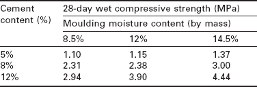
The results given in Table 13.2 show that the compressive strength of cement-stabilised compacted soil specimens increases with an increase in moulding water content. For 5% and 8% cement contents, the strength increase was about 30% when the moulding moisture content was increased from 8.5% to 14.5%, whilst strength increased by nearly 50% for the higher 12% cement content. A dry soil–cement mixture contains cement and clay particles, both with an affinity for water. When water is added to the dry soil–cement mixture, it is shared by both the cement and clay particles. When the samples are compacted using a small quantity of moulding water (say 8%), it is possible that there could be insufficient water for proper hydration of the cement to take place. As the moulding water content is increased (say to 14.5%), more water is available for cement hydration. Specimens compacted with a higher moulding water content can also suffer higher shrinkage, leading to a marginal increase in density, and this increased density can result in higher compressive strength (which might explain why there is an increased strength when a higher percentage of moulding water is used). These results clearly indicate the advantages of using a higher moulding water content during the manufacture of cement SSBs.
13.4.4 Type and quantity of stabiliser on the stabilised soil block strength
As already noted, a variety of stabiliser additives can be used for the production of SSBs. Lime and Portland cement are the most commonly used stabilisers, and the following discussion of stabiliser influence on strength is restricted to these two.
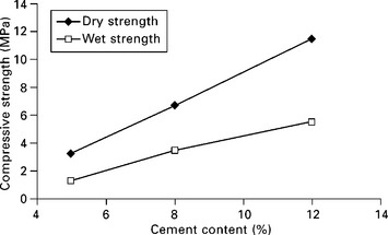
The selection of lime or cement for the production of SSBs depends on the clay minerals present in the soil used for such blocks. Ordinary Portland cement (OPC) is the most commonly employed stabiliser and is an ideal stabiliser for coarse-grained soils with less-expansive clay minerals. The strength of CSSBs increases with an increase in cement content. Generally, the cement content used for CSSBs is in the range of 5–10%. For a given block density, the percentage increase in strength as the cement content increases depends on the clay content of the mix used. Typical variations in strength as cement content is varied are illustrated in Fig. 13.12 for blocks using a sandy soil with 7% cement. As the cement content is increased, the percentage increase in strength (or the slope of the lines on the graph) can vary depending upon the clay fraction of the mix and also on the block density. Selection of the percentage of cement content for production of CSSBs is dependent on the compressive strength of the block desired.
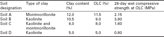
Generally, lime in the form of calcium hydroxide is used for SSB production. Lime stabilisation becomes essential when handling soils containing expansive clay minerals, mainly to address the issue of high swelling and shrinkage characteristics, but it is also used for SSB production using soils with nonexpansive clays. Figure 13.13 shows strength variations in lime-stabilised compacts when lime content is varied, and shows that there is an optimum lime content (OLC) yielding maximum strength, which varies from soil to soil. Table 13.3 summarises the OLC and strength for the four types of curve shown in Fig. 13.13. Type of clay mineral, percentage of clay, OLC and 28-day compressive strength values are also detailed in Table 13.3. It is interesting to note that there is a relationship between OLC and the clay type and its percentage in the mix, with OLC almost exactly corresponding to the clay content of the soil mix, and increasing with the increase in clay content of the soil.
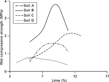
The results of the parametric studies discussed above relate to the unconfined compressive strength of smaller size specimens. The wet compressive strength of CSSBs (size: 230 × 190 × 100 mm) with 7% cement (OPC) used for load bearing masonry is in the range of 5–7 MPa (Ullas and Venkatarama Reddy, 2007), whilst the wet compressive strength of lime-stabilised blocks (8-10% lime) is in the range of 1.5–2 MPa.
13.4.5 Absorption characteristics of stabilised soil blocks
SSB absorption characteristics include properties such as rate of water absorption, initial rate of absorption (IRA) and the saturated water content (called water absorption) of the blocks. The percentage of clay minerals present in the block, quantity of stabiliser, density, porosity and pore size distribution of an SSB control these properties. Investigations by Walker and Stace (1997), Venkatarama Reddy et al. (2007a), Venkatarama Reddy and Gupta (2005b), and Venkatarama Reddy and Vyas (2008) are just some of the studies that have been made on SSB absorption characteristics.
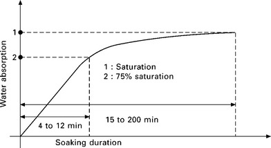
Figure 13.14 shows water absorption rates for CSSBs with various soaking durations in water. When dry blocks are soaked in water, the rate of water absorption is highest in the initial few minutes. CSSB blocks require 4–12 minutes to attain 75% saturation, and 15–200 minutes to attain complete saturation. The rate of water absorption is a function of density, soil grading and cement content. Soaking duration to achieve 75% and 100% saturation decreases with an increase in cement content and density of the blocks (Venkatarama Reddy and Gupta, 2005b).
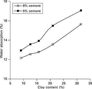
The saturated water content (or water absorption) of CSSBs increases with an increase in the clay content of the blocks. Typical relationships between water absorption and block clay content (having a dry density of 1800 kg/m3) are shown in Fig. 13.15 (Prasanna Kumar, 2010). Saturated water content values for CSSBs with a clay content of about 15% lie in a range of 10–16% for blocks with 7–10% cement content.
IRA for CSSBs decreases with an increase in the clay fraction of the block. The lower IRA values at higher clay content can be attributed to the low surface porosity of the blocks. As the clay content of the block increases, the percentage of fines in the block increases and can lead to lower surface porosity leading to lower absorption rates. Typical IRA values for blocks with 15% clay are about 2 kg/m2/minute, as compared with 1–3 kg/m2/minute for a variety of burnt clay bricks.
13.4.6 Stabilised soil block (SSB) durability
Durability of SSB buildings is a major concern expressed by the users of SSB technology. Several accelerated test methods have been devised to assess the durability of SSBs, including: (i) the spray erosion test; (ii) the drip test; (iii) the alternate wetting and drying test; and (iv) the linear expansion on saturation test. Each of these tests will now be considered in turn.
Spray erosion test
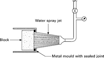
Several attempts have been made to standardise the spray erosion test (Middleton, 1952; Venkatarama Reddy and Jagadish, 1995 and 1987; Walker, 1998; Heathcote, 1995 and 2001, Walker, 2004). Walker (1998) highlights the different types of test procedures available to assess erosion resistance of soil blocks. A typical test procedure involves spraying a jet of water (at constant pressure) onto the surface of a stabilised soil block for a given time. After the test, the block surface is monitored for pitting, surface erosion (erosion depth) and weight of the material removed by the water jet. Depth of erosion and mass loss are quantified and correlated to the durability of stabilised soil blocks. Many investigators have attempted to make the spray erosion test represent more closely the damage caused by raindrops on a wall surface. Figure 13.16 shows a typical spray erosion test set-up. accelerated spray erosion tests can at best give only some idea about the relative performance of an SSB. many attempts have been made to correlate erosion rates with field erosion rates due to natural rainfall (Venkatarama Reddy and Jagadish, 1987); however, standardisation becomes a problem because the nature, intensity, amount and distribution of rainfall varies considerably from region to region.
The drip test
The drip test basically involves allowing water droplets or drips to impinge on an inclined block surface for a given time (Yttrup et al., 1981). After the test, the block surface is monitored for pitting and depth of erosion. This type of test again gives a relative evaluation of the durability performance of different types of SSBs.
It has been observed that SSBs with adequate stabiliser content and manufactured using soils with optimum clay content perform exceedingly well when subjected to both spray erosion and drip tests. Evaluating the relative performance of SSBs with stabiliser content beyond a threshold limit becomes difficult because the surfaces of such blocks do not show any erosion, even after several hours of exposure to water spray (Venkatarama Reddy and Jagadish, 1987; Walker, 2004).
Alternate wetting and drying test
This cyclic wetting and drying test examines the durability of SSBs, with the test procedure and guidelines being supplied by the ASTM D559 code. The test involves monitoring weight loss after 12 cycles of cyclic wetting and drying and the brief test procedure is as follows:
1. Ascertain the initial dry block weight after drying it to constant weight in an oven
2. Soak the dried specimens in potable water at room temperature for a period of 5 hours and then dry them in an oven at 71 °C for 42 hours. Apply two firm strokes on surfaces of the partially dried specimens with a standard wire brush. Eighteen to 20 strokes are applied to cover all the sides of the specimens (see ASTM D559 code). This constitutes one cycle of wetting and drying
3. Repeat the same procedure and complete 12 cycles
4. At the end of 12 cycles, oven dry specimens again at 60 °C until they attain constant weight and record the final dry weight
5. Estimate the weight loss to ascertain mass loss after 12 cycles of the wetting and drying test.
This test, involving scratching the specimen with a metal wire brush, is considered too severe a test to evaluate the durability of SSBs (Lunt, 1980).
The Portland Cement Association (1956) specified acceptable limits for weight loss ranging from 7 to 14% for various types of soils when used with cement for road construction. These limits have been modified and adopted by several authorities over the years, according to the nature and type of construction and climatic conditions. For example Fitzmaurice (1958) recommended limits for maximum weight loss as 5% for permanent buildings and 10% for rural buildings in any type of climate; Walker and Stace (1997) attempted to correlate mass loss with the clay content of the cement–soil mix used for block production.
Tests performed on a variety of SSBs and also on blocks collected from different buildings with age distributions ranging between 5 and 14 years show useful results to specify a limit for weight loss. After investigations by Venkatarama Reddy et al. (2003), Venkatarama Reddy (2007), Venkatarama Reddy and Jagadish (1995), and observations of the performance of real time SSB buildings, a limit of 3% weight loss has been specified by Venkatarama Reddy (2007) and is being adopted by the revised Indian code of stabilised soil blocks.
Linear expansion on saturation
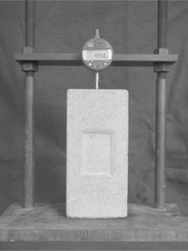
An accurate length comparator is an essential tool for performing any test for linear expansion on saturation. A typical experimental set-up is shown in Fig. 13.17. The test involves measuring the initial length of an oven dried (at 50 °C) block, soaking the oven dried block in water for 24 hours, and then measuring the length of the saturated block. The difference in the lengths of the dry and saturated block gives the linear expansion of the block on saturation.
Venkatarama Reddy (2002), Ullas and Venkatarama Reddy (2007) and Venkatarama Reddy et al. (2003) examined the performance of existing CSSB buildings with exposed block-work walls (without protection), with age distributions ranging between 5 and 14 years. They monitored linear expansion on saturation for the blocks collected from several of these constructions, and established a correlation between the performances of these buildings (the extent of damage) with linear expansion on saturation of the CSSBs collected. These results indicate that the use of SSBs with < 0.10% linear expansion on saturation generally leads to satisfactory performance of SSB buildings when exposed to alternate wetting and drying caused by rain and sunlight over a period of several years.
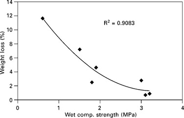
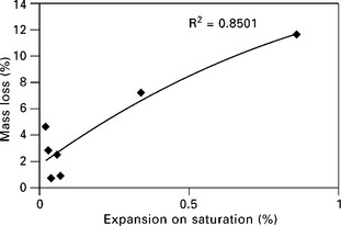
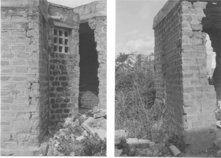
Figures 13.18 and 13.19 show the relationships between mass loss and strength, and mass loss and linear expansion as reported by Venkatarama Reddy et al. (2003). Figures 13.20 and 13.21 show CSSB wall surfaces after exposure for 14 years (with linear expansion on saturation of 2.32%) and 11 years (with linear expansion on saturation of 0.03%), respectively. A large value for linear expansion on saturation indicates severe damage to the block and wall surface after repeated wetting and drying caused by the natural weathering process. If an SSB has a smaller value for linear expansion on saturation, the wall surface is likely to be intact even after several years of weathering. Hence, keeping linear expansion less than 0.10% and mass loss after the wetting and drying test below 3% could assure stable long-term performance for the SSBs. The test for linear expansion on saturation can also be conducted in the field to assess block quality, and blocks having < 0.10% linear expansion have performed satisfactorily in such field tests. The linear expansion on saturation value can be bench marked to indicate the dimensional stability of an SSB under natural weathering conditions.
13.4.7 Stress–strain characteristics
Stress–strain relationships and stress–strain characteristics such as modulus, Poisson ratio, strain at peak stress and ultimate failure strains for SSBs depend on the following parameters:
1. composition of the soil–sand mixture, especially the percentage of clay mineral
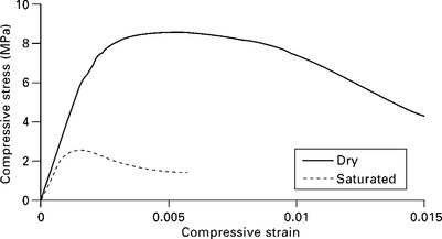
Comprehensive studies on the stress–strain relationships and elastic properties of SSBs are limited. Investigations by Venkatarama Reddy and Jagadish (1989), Venkatarama Reddy and Gupta (2005b), Venkatarama Reddy et al. (2007b), Venkatarama Reddy and Vyas (2008) and Walker (2004) throw some light on the stress–strain relationships for CSSBs. Investigations by Kouakou and Morel (2009), and Maniatidis and Walker (2008) provide information on stress–strain relationships for unstabilised compacted soil blocks. The initial tangent modulus (in saturated state) for CSSBs is in the range of 3000–4500 MPa for 7–8% cement blocks with a density of 1800 kg/m3. Typical stress–strain relationships for CSSBs (with an optimum clay content of about 15%) in dry and saturated conditions are illustrated in Fig. 13.22. The stress–strain behaviour for CSSBs shows a large softening portion beyond peak stress. The ultimate strain at failure is in excess of 1.5% for CSSBs in dry condition, whereas in a saturated state the blocks have an ultimate failure strain of about 0.5–0.6%. Strain at peak stress is in the range of 0.002–0.004. The Poisson ratio increases with the increase in clay content of the block, and can be as high as 0.24 for low cement content and high clay fraction. Generally, for blocks with 6–8% cement (and dry density > 1800 kg/m3) with an optimum clay content of 15% and using coarse-grained soils, the Poisson ratio is in the range of 0.10–0.18 in the saturated state (Venkatarama Reddy et al., 2007b; Gupta, 2004; Vyas, 2007).
13.5 Cement–soil mortars for stabilised soil block masonry
Clearly, an important role for any mortar in masonry is to develop a good bond with the masonry unit and prevent moisture ingress through the mortar joint. Cement mortar and cement–lime mortar are the commonly used conventional mortars for masonry. Pure cement mortars, especially the leaner mortars, have poor workability characteristics coupled with low water retentivity and develop poor bond strength. Cement–lime mortar possesses good workability, water retentivity and better bond strength when compared to pure cement mortars. Replacing lime with soil in cement–lime mortar results in cement–soil mortar. Cement–soil mortars are economical and possess better properties when compared to conventional mortars. Such mortars are commonly used for SSB masonry in many countries.
Cement–soil mortars are composed of OPC, soil and sand with the requisite quantity of water. Such mortars can be prepared on-site by carefully mixing the raw materials to a desired consistency. Soils containing less expansive clay minerals such as kaolinite can be used. Both natural river sand and manufactured sand (conforming to the general requirements mentioned in standard codes of practice for mortars) can be used. Advantages of cement–soil mortars are: (i) superior workability and better water retentivity, and no segregation even at very high water–cement ratio; (ii) higher masonry bond strength; (iii) lower cost; and (iv) they possess natural soil texture. A detailed discussion of cement–soil mortars can be found in Walker and Stace (1997) and Venkatarama Reddy and Gupta (2005a).
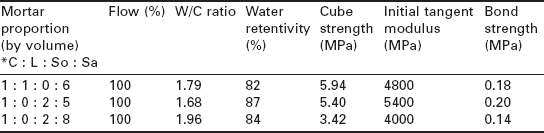
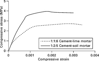
Table 13.4 gives details of some typical characteristics of commonly used cement–soil and cement–lime mortars (Gupta, 2004; Venkatarama Reddy and Gupta, 2005a). Workability of mortars can be quantified by measuring the flow value. Gupta (2004) measured the flow values of fresh mortars used by masons for the construction of SSB masonry and found that a mortar with a flow of about 100% was preferred. To achieve a flow of 100%, the water–cement ratio differs amongst mortars with different compositions. Water retentivity of cement–soil mortars is more than that of conventional cement–sand mortar. Whilst the compressive strengths of cement–lime mortar (1:1:6) and cement–soil mortar (1:2:5) are comparable, the masonry bond strength of cement–soil mortar is superior to that of cement–lime mortar. Figure 13.23 shows stress–strain relationships for conventional cement–lime mortar and cement–soil mortar.
13.6 Stabilised soil block masonry
Masonry is a layered composite structure consisting of masonry units and mortar. Structural behaviour of SSB masonry is influenced by the strength and deformation characteristics of the blocks and the mortar. Generally, the two materials have different strengths and elastic properties. The strength of SSB masonry is influenced by a large number of factors, such as block strength, block height, mortar strength, mortar joint thickness, modulus and Poisson ratio of the mortar and direction of loading.
13.6.1 Stabilised soil block masonry strength and design guidance
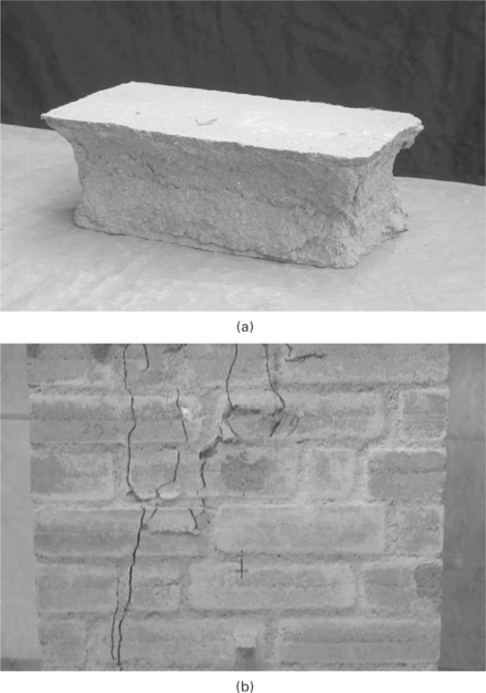
The compressive strength of masonry is less than that of the compressive strength of the individual brick or block. this is attributed to the development of splitting tensile cracks developed in a masonry unit due to the differing deformation characteristics of the masonry unit and the mortar. typical failure patterns of a brick or block and masonry prism are shown in Fig. 13.24. These failure patterns clearly show that the brick or block fails in shear, as a result of platen friction, whereas the masonry prism and wall fail due to the development of vertical splitting cracks. Vertical splitting cracks indicate that the bricks or blocks in the masonry wall are subjected to tensile stresses even though they are loaded in compression. this is due to the differing modulus values for the bricks and the mortar. In addition to the magnitude of compressive loads, slenderness ratio and load eccentricity also influence the compressive strength of masonry walls. For a given mortar–block combination, the compressive strength of a wall is much less than that of a block.
Investigations by Venkatarama Reddy and Jagadish (1989), Shrinivasa Rao et al. (1995), Walker (2004), Venkatarama Reddy et al. (2007b), Venkatarama Reddy and Vyas (2008) and Venkatarama Reddy and Gupta (2008) throw some light on the strength of cement SSB masonry. Table 13.5 gives a compilation of the compressive strength (wet) of cement SSB masonry prisms extracted from the above mentioned investigations. A range of block strengths (2.5–11.5 MPa) and mortar strengths (0.75–9.40 MPa) have been considered to arrive at the masonry prism strengths. the prism strength to block strength ratio is in the range of 0.43–0.52, except in a few cases where it is more than 0.60. Masonry prism strength is not very sensitive to mortar strength. there is a large scope for understanding the block aspect ratio (height to width) on masonry compressive strength. Given the limited data on masonry strength, the relationship between masonry prism strength and block strength can be used to assess the compressive strength of masonry walls. Assuming a conservative value of prism to block strength ratio of 0.40, the masonry prism strength can be assumed to be 0.40 times the block strength. this value of prism strength can lead to an assessment of either characteristic compressive strength or basic compressive stress of SSB masonry. If working stress design principles are used, the basic compressive stress of SSB masonry can be obtained, being the prism strength divided by a factor of 4 (as per the IS 1905 code). A brief summary of masonry design procedures using working stress design principles is given below.
Table 13.5
Strength of stabilised soil blocks and masonry
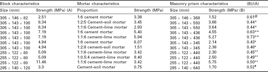
@Venkatarama Reddy and Jagadish (1989);
*Venkatarama Reddy et al. 2007b;
**Venkatarama Reddy and Gupta (2008);
+Rao et al. (1995);
Procedure for the design of a masonry wall under vertical gravity loads
1. First, assume the masonry wall thickness
2. Estimate the total load realised on the wall and compressive stress developed at the base of the wall
3. Determine the slenderness ratio and eccentricity (using masonry code guidelines) and obtain the stress reduction factors from the code
4. Allowable compressive stress = (basic compressive stress) × (stress reduction factors)
5. Equate allowable compressive stress to the compressive stress developed at the base of the wall and obtain the basic compressive stress value
6. Masonry design codes give relationships (either in tabular form or graphical form) between the masonry unit strength, mortar type and basic compressive stress. For any computed value of basic compressive stress, select brick or block strength and mortar type from such relationships, under concentric and eccentric loads.
Similar design procedures can be evolved using limit state design principles provided a procedure is established to compute the characteristic compressive strength of SSB masonry using masonry prism strength values. there is still scope for further comprehensive investigations to be undertaken into the behaviour of full-scale SSB masonry walls.
13.7 Long-term performance, repair and retrofitting of stabilised soil block buildings
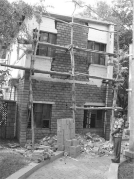
Satisfactory performance of an SSB masonry building is the building owner’s most important concern. Deterioration/weathering of SSB walls can be attributed to various factors relating to material composition of the block, and to disintegration caused by mechanical means. Clay minerals present in the blocks (and with a lot of affinity for water) are a major contributing factor for deterioration of SSBs. Unstabilised clay pockets present in the blocks can absorb water and undergo swelling, and then shrink on drying; this process can manifest as surface cracks, and further cycles of wetting and drying can disrupt the established cementitious bonds between various particles causing deterioration of the SSBs with age. Frost action can also damage and cause deterioration. Hence, the quantity of clay present in the SSBs, the percentage of stabiliser used, and the extent of exposure to cyclic wetting and drying can all control the long-term performance of SSBs. Figure 13.25 shows cracking and deterioration of SSB walls. Blocks present at the corners and edges of walls, window sills and jambs are more prone to such types of failures, which can damage walls considerably and lead to collapse of a structure. All such types of damage can be attributed to inadequate stabilisation of clay minerals in the soil used for the SSBs.
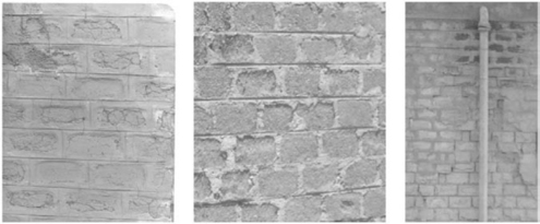
13.25 Different types of SSB wall damage and failure (L–R: Splitting cracks; erosion and pitting; spalling).
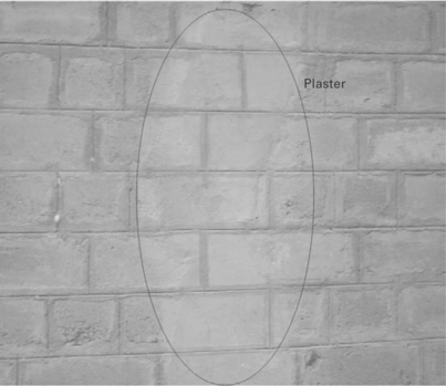
Damaged and deteriorated SSB walls can be repaired and retrofitted either by patch plastering or by progressively replacing the damaged parts. Patch plastering repairs the cracks, pitting, spalling and damaged surface of SSB walls whilst using a compatible mortar. Here, the compatibility is in terms of shrinkage characteristics of the mortar and the SSB, mainly to avoid differential shrinkage between the block and the patched up mortar on the damaged surface. Cement–soil mortars with a clay fraction of about 10% and cement content of 10–12% are compatible, and hence such mortars can be used for the patch plastering of damaged SSB block surfaces. Figure 13.26 shows a patch plastered surface performing satisfactorily.
Severe damage to walls can jeopardise the safety of a building and could lead to collapse. Progressively replacing a badly damaged or partly collapsed SSB wall can repair it without disturbing the neighbouring portions. Figure 13.27 shows an SSB wall that has been retrofitted without disturbing the first floor wall (Venkatarama Reddy, 2008a).
13.8 Case studies of cement-stabilised soil block (CSSB) buildings
A variety of load-bearing masonry CSSB buildings have been built across India and a number of case studies are highlighted here.
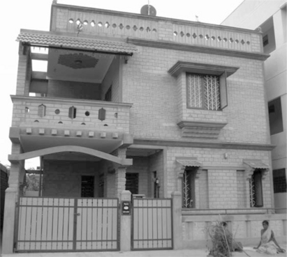
13.8.1 Residential building, Bangalore, India (Fig. 13.28)
This two-storey building (with a provision for one more floor) has load-bearing SSB masonry walls (230 mm thickness) in cement–soil mortar and was built in 2000. The blocks of size 230 × 190 × 100 mm were manufactured with 9% Portland cement on-site, using a portable manual machine. Soil processing and block manufacturing was a completely manual operation. The wet compressive strength of the block was 6.5 MPa (courtesy: Design and construction by Dr M. R. Yogananada, Bangalore, India).
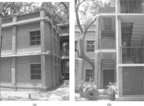
13.8.2 Seminar hall complex, Indian Institute of Science, Bangalore, India (Fig. 13.29)
This is a two-storey load-bearing CSSB masonry wall building (with provision for one more floor) and was built in 2004. The ground floor consists of a seminar hall (clear span = 6.25 m) attached to a staircase room. The walls are 230 mm thick built using 230 × 190 × 100 mm blocks and a cement–soil mortar. Exposed block-work outside and the interior wall faces are plastered with cement–soil mortar. The wet compressive strength of the CSSBs with 8% cement was 7.0 MPa. The floors and roof for the main hall are made up of composite masonry jack-arch using CSSB blocks. The staircase portion has a CSSB filler slab floor/roof (courtesy: Design and construction by Prof. B. V. Venkatarama Reddy, Indian Institute of Science, Bangalore, India).
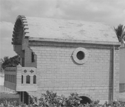
13.8.3 Cement-stabilised soil block (CSSB) masonry vault and CSSB decorative features (Fig. 13.30)
This CSSB masonry vault was built using cement–soil mortar in 1995. The vault span is 3.5 m, with a thickness of 143 mm. CSSB corbelled blocks and decorative jali block masonry was used for the balcony. This is a three-storey load-bearing CSSB masonry building with 190-mm thick walls (courtesy: Design and construction by Dr M. R. Yogananada, Bangalore, India).
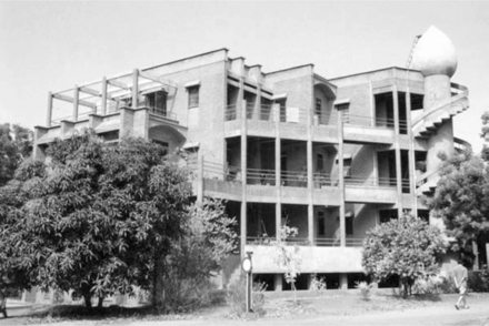
13.8.4 Vikas Project, Auroville, India (13.31)
This four-storey load-bearing masonry residential building complex was built using CSSB blocks in cement–soil mortar during 1991–1998. The complex has a cellar portion with cement-stabilised rammed earth foundation. The soil excavated in the cellar was utilised for the production of CSSB blocks. The masonry walls are 240 mm thick. The CSSBs and rammed earth were stabilised with 5% Portland cement. The floor and roofing system consists of unreinforced masonry vaults. This project was a Finalist for the 2000 World Habitat Award, UK (courtesy: design and construction by mr Satprem, Auroville, Pondicherry, India).
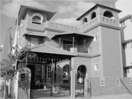
13.8.5 Multi-storey residential building, Bangalore, India (Fig. 13.32)
This multi-storey (basement plus three floors) load-bearing masonry residential building using CSSB masonry in cement–soil mortar was built during 2006. The walls are 230-mm thick. CSSB compressive strength (wet) was 9 MPa for the blocks used in the basement floor and 7 MPa for blocks in subsequent floors. The block strength was conveniently adjusted by using 12% Portland cement for the blocks used in the basement floor and 9% cement for the blocks in the other floors. The CSSB blocks were manufactured on-site using a portable manually operated machine (courtesy: design and construction by Dr M. R. Yogananada, Bangalore, India).
13.9 References
ASTM D 559–03. Standard test methods for wetting and drying compacted soil-cement mixtures. Pennsylvania: American Society for Testing and Materials; 2003.
Chaston, F.N. Soil-cement progress in Australia. The Indian Concrete Journal. 1952; 26(12):354–356.
Department of Housing and Urban Development. Earth for homes. Washington DC: Division of International Affairs; 1955. [20140].
Fitzmaurice, R.F. Manual on stabilised soil construction for housing. New York: UN Technical Assistance Program; 1958.
Gupta, A., Studies on characteristics of cement–soil mortars and soil-cement block masonry MSc (Engg.) thesis, Dept. of Civil Engineering. Indian Institute of Science, Bangalore, India, 2004.
Heathcote, K. Compressive strength of cement stabilised pressed earth blocks. Building Research and Information. 1991; 19(2):101–105.
Heathcote, K. Durability of earth wall buildings. Construction and Building Materials. 1995; 9(3):185–189.
Heathcote, K., An investigation into the erosion of earth walls PhD thesis. University of Technology, Sydney, 2001.
Houben, H., Guillaud, H. Earth Construction – A Comprehensive Guide, CRATerre-EAG. Belgium: Intermediate Technology Publications; 2003.
I S 1905. Code of practice for structural use of unreinforced masonry. New Delhi, India: Bureau of Indian Standards; 1987.
Kouakou, C.H., Morel, J.C. Strength and elasto-plastic properties of non-industrial building materials manufactured with clay as a natural binder. Applied Clay Science. 2009; 44:27–34.
Lambe, T.W. Soil stabilisation. In: Leonards G.A., ed. Foundation Engineering. New York: McGraw Hill Book Co. Inc; 1962:351–437.
Lunt, M.G. Stabilised soil blocks for buildings. Overseas Building Notes. 1980; 184.
Madhavan, R., Narasinga Rao, C.N. Report on Labour Housing Scheme. Bangalore, India: The City Improvement Trust Board; 1949.
Maniatidis, V., Walker, P. Structural capacity of rammed earth in compression. J of Mat. in Civil Engineering (ASCE). 2008; 20(3):230–238.
Middleton, G.F., Earth-wall construction (revised by Schneider, L. M., 1987), 4th ed. Bulletin; 5. Commonwealth Scientific and Industrial Research Organization, Australia, 1952.
Mitra, J.N. Suitability of soil for stabilised soil houses for Rangawan dam colony. Indian Concrete Journal. 1951; 15:234–238.
Mukerji, K., Soil block presses report on Global survey, GATE, Dag-Hammerxjold-weg, 1, 6236. Eschborn, Germany, 1986.
Olivier, M., Le matériau terre-compactage, comportement, application aux structures en blocs de terre PhD thesis. Institut National des Sciences Appliquées, Lyon, France, 1994.
Olivier, M., Mesbah, A., Influence of different parameters on the resistance of earth, used as a building material. Proceedings of the International Conference on Mud Architecture, Trivandrum, India, 1987.
Portland Cement Association. Soil-cement laboratory handbook. Skokie, Ill: Portland Cement Association; 1956.
Prasanna Kumar, P., Stabilised rammed earth for walls: materials, compressive strength and elastic properties PhD thesis, Dept. of Civil Engineering. Indian Institute of Science, Bangalore, India, 2010.
Shrinivasa Rao, S., Venkatarama Reddy, B.V., Jagadish, K.S. Strength characteristics of soil-cement block masonry. The Indian Concrete Journal. 1995; 69(2):127–131.
Spence, R.J.S. Predicting the performance of soil-cement as a building material in tropical countries. Building Science. 1975; 10:155–159.
Ullas, S.N., Venkatarama Reddy, B.V. Characteristics of soil-cement blocks from different construction sites. In: Proceedings of the International Symposium on Earthen Structures. Bangalore, India: Interline Publishers; 2007:141–146.
Un Report, Soil-cement – its use in building Dept. of Economics and Social Affairs. United Nations, New York, 1964.
Venkatarama Reddy, B.V., On the technology of pressed soil blocks for wall construction MSc (engg) thesis, Dept. of Civil engineering. Indian Institute of Science, Bangalore, India, 1983.
Venkatarama Reddy, B.V., Studies on static soil compaction and compacted soil-cement blocks for walls PhD thesis, Dept. of Civil Engineering. Indian Institute of Science, Bangalore, India, 1991.
Venkatarama Reddy, B.V., Long-term strength and durability of stabilised mud blocks. Proceedings of the 3rd International Conference on Non-conventional Materials and Technologies. Construction Publishing House, Hanoi, Vietnam, 2002:422–431.
Venkatarama Reddy, B.V. Indian standard code of practice for manufacture and use of stabilised mud blocks for masonry. In: Proceedings of the International Symposium on Earthen Structures. Bangalore, India: Interline Publishers; 2007:194–202.
Venkatarama Reddy, B.V., Retrofitting of damaged stabilised earth block buildings. Proceedings of the 5th International Conference on Building with Earth (LEHM 2008), 10–12 October, Koblanz Germany. Dachverband Lehm e.V, Germany, 2008:4–111.
Venkatarama Reddy, B.V., The stabilised mud block: a low carbon emission alternative for masonry buildings. Proceedings of the First International Conference on Building Energy and Environment (C0BEE-2008), Dalian, China, 13–16 July. 2008:1397–1404.
Venkatarama Reddy, B.V. Sustainable materials for low carbon buildings. International Journal of Low Carbon Technologies. 2009; 4(3):175–181.
Venkatarama Reddy, B.V., Gupta, A. Characteristics of cement–soil mortars. Materials and Structures (RILEM). 2005; 38(280):639–650.
Venkatarama Reddy, B.V., Gupta, A. Characteristics of soil-cement blocks using highly sandy soils. Materials and Structures (RILEM). 2005; 38(280):651–658.
Venkatarama Reddy, B.V., Gupta, A. Strength and elastic properties of stabilised mud block masonry using cement soil mortars. J. of Mat. in Civil Eng. 2006; 18(3):472–476.
Venkatarama Reddy, B.V., Gupta, A. Influence of sand grading on the characteristics of mortars and soil-cement block masonry. Construction and Building Materials. 2008; 22(8):614–1623.
Venkatarama Reddy, B.V., Hubli, S.R. Properties of lime stabilised steamcured blocks for masonry. Materials and Structures (RILEM). 2002; 35:293–300.
Venkatarama Reddy, B.V., Jagadish, K.S. Pressed soil-lime blocks for building construction. Masonry International. 1984; 3:80–84.
Venkatarama Reddy, B.V., Jagadish, K.S. Spray erosion studies on pressed soil blocks. Building and Environment. 1987; 22(2):135–140.
Venkatarama Reddy, B.V., Jagadish, K.S. Properties of soil-cement block masonry. Masonry International. 1989; 3(2):80–84.
Venkatarama Reddy, B.V., Jagadish, K.S. The static compaction of soils. Geotechnique. 1993; 43(2):337–341.
Venkatarama Reddy, B.V., Jagadish, K.S. Influence of soil composition on the strength and durability of soil-cement blocks. The Indian Concrete Journal. 1995; 69(9):517–524.
Venkatarama Reddy, B.V., Lokras, S.S. Steam-cured stabilised soil blocks for masonry construction. Energy and Buildings. 1998; 29:29–33.
Venkatarama Reddy, B.V., Vyas, U.C.V. Influence of shear bond strength on compressive strength and stress strain characteristics of masonry. Materials and Structures (RILEM). 2008; 41(10):1697–1712.
Venkatarama Reddy, B.V., Walker, P., Stabilised mud blocks: problems, prospects. Proceedings of the International Earth Building Conference, Sydney, Australia. 2005:63–75.
Venkatarama Reddy, B.V., Richardson, L., Nanjunda Rao, K.S. Optimum soil grading for the soil-cement blocks. J. of Mat. in Civil Eng. 2007; 19(2):139–148.
Venkatarama Reddy, B.V., Richardson, L., Nanjunda Rao, K.S. Enhancing bond strength and characteristics of soil-cement block masonry. J. of Mat. in Civil Eng. (ASCE). 2007; 19(2):164–172.
Venkatarama Reddy, B.V., Richardson, L., Nanjunda Rao, K.S. Influence of joint thickness and mortar-block elastic properties on the strength and stresses developed in soil-cement block masonry. J of Mat. in Civil Eng. 2009; 21(10):535–542.
Venkatarama Reddy, B.V., Williams, T., Walker, P., Durability of stabilised mud block buildings in Southern India. Proceedings of the 9th International Conference on the Study and Conservation of Earthen Architecture (Terra-2003), Yazd, Iran. 2003:492–503.
Vyas, U.C.V., Studies on shear bond strength - masonry compressive strength relationships and finite element model for prediction of masonry compressive strength MSc (engg) thesis, Dept. of Civil engineering. Indian Institute of Science, Bangalore, India, 2007.
Walker, P., Erosion testing of compressed earth blocks. Proceedings of the 5th International Masonry Conference, London, UK. 1998:264–268.
Walker, P. Bond characteristics of earth block masonry. J. Mater. Civ. Eng. 1999; 11(3):249–256.
Walker, P. Strength and erosion characteristics of earth blocks, and earth block masonry. J. Mater. Civ. Eng. 2004; 16(5):497–506.
Walker, P., Stace, T. Properties of some cement stabilised compressed earth blocks and mortars. Mater. Struct. 1997; 30:545–551.
Walker, P., Venkatarama Reddy, B.V., Mesbah, A., Morel, J.-C., The case for compressed earth block construction. Proceedings of the 6th International Seminar on Structural Masonry for Developing Countries, Bangalore, India. 2000:27–35.
Yttrup, P.J., Diviny, K., Sottile, F. Development of drip test for the erodibility of mud bricks. Geelong, Australia: Deakin University; 1981.