Australian modern earth construction
Abstract:
This chapter describes the stabilised rammed earth (SRE) industry in Australia. It outlines the construction systems used, the design parameters that have proven successful and the technical specifications used to monitor the product. It also explains the market place of SRE within the Australian social and economic environment. Finally it looks at the future of SRE in the Australian and global context.
22.1 Introduction
Thirty years ago a small team of Western Australian entrepreneurs developed new technologies to modernise an ancient building method, rammed earth. They created a successful Australian version of stabilised rammed earth (SRE) complete with new formwork systems, new business structures and rigorous building design concepts. This chapter will describe Australian soil selection procedures, construction systems, building design and market trends. SRE is the focus of this chapter as it appears to define modern earth wall construction in Australia.
In Australia, stabilised rammed earth is known by designers and engineers as the acronym SRE. SRE walls are the product of blending aggregates, sand and cement stabilisers with enough water and waterproofing admixtures to achieve a damp, optimally compactable compound. This compound is then placed within specialised in situ formwork and rammed using pneumatic tools in 150-mm layers to create a dense, water resistant and structurally useful wall panel. SRE buildings consist of a series of interlocking load-bearing monolith panels.
The appearance of the walls is an off-form sedimentary finish with the natural colours and textures of the aggregates being the defining feature. Australian designers have not embraced the coloured ‘banding’ of walls as often seen in North American buildings. The oxides used in these walls trump the natural colours of the base materials and the rainbow cake banding has been considered a distraction from the otherwise humble beauty of the walls.
22.2 Uses of stabilised rammed earth in different regions of Australia
22.2.1 The effect of regional climatic zones on earth building
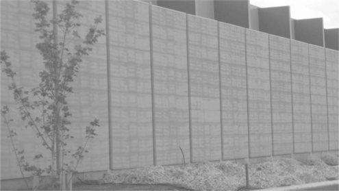
For the purpose of describing Australian climate in terms of its suitability for earth building, there are two basic zones that can be identified (see Fig. 22.1).
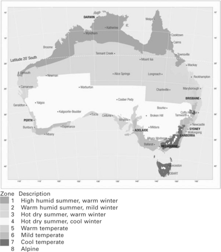
First the humid tropical zone north of Rockhampton, Queensland, which extends in a roughly 200- to 500-km-wide strip around the northern coastline as far as Broome on the west coast. This zone is unsuitable for solid masonry building. Consistently warm to hot day and night temperatures are accompanied by high humidity. solid masonry walls cannot release their accumulated daytime heat throughout the evening. Solid masonry dwellings in this zone become uncomfortably hot and humid. Most contemporary Australian buildings in this climate area are built using lightweight timber or iron cladding, which cools down quickly unlike solid masonry.
Second the temperate zone, which extends below the tropical zone. In this zone there is low humidity, and summer night temperatures regularly drop to levels that allow solid masonry walls to adequately cool. Many contemporary earth buildings in this zone do not require air conditioning although they do need to be ‘managed’ by the occupants.
This management includes drawing curtains or shutters during the heat of the day and opening windows and doors at night to allow the ‘dumping’ of cool air through the building. To be effective, these buildings also require appropriate design with large north-facing openings to allow winter sun into interior living spaces, cross-flow ventilation for night-time cooling and protection from afternoon summer sun.
Some buildings in our alpine areas may require insulated walling, especially on sites subject to shading that would decrease sunlight on winter days.
22.2.2 Earth building in rural areas
Fewer than 15% of Australians live in rural areas.1 However, over the past 30 years a majority of modern earth buildings have been rural or semi-rural for the following simple reasons.
Firstly, in terms of earth building, rural sites are easier to access and work on than urban sites. SRE construction requires adequate space for stockpiling and blending of materials and the storage of formwork during construction. Delivery of base materials to rural sites using cheaper truck and trailer combinations is easy. Accommodation for construction teams in rural areas is inevitably cheaper and nicer than in cities. Earth building on small, inaccessible urban sites is often cost prohibitive.
Secondly, more earth building clients have been likely to want an earth house in the country rather than the city. Culturally there has been an acceptance of earth building in rural and semi-rural districts, though this is changing.
We have no data on this, but earth building in Australian cities could traditionally be considered high risk in terms of acceptance and resale.
22.2.3 Earth building in urban areas
There are, however, an increasing number of urban buildings built using contemporary earth walling, particularly in Western Australia where the revival of rammed earth as a modern building medium has been particularly prolific.
Alan Brooks, an SRE contractor based in Perth says almost 90% of his current work is urban. He sources limestone rubble and recycled concrete from crushing plants often within the city itself so they can rely on quick deliveries of materials eliminating the need for stockpiling on small sites. Urban SRE is now their main business and they have developed tricks to streamline their production and keep costs down. In other parts of Australia this trend toward more urban earth wall construction is also growing.
Scott Kinsmore is a rammed earth contractor in Melbourne. He says he is building higher walls on smaller urban sites. The engineering for higher walls with more point-specific loads on small-site buildings is challenging and often requires more steel to be built within the wall structures. This can be frustrating and costly for the wall builder. Increasingly, Australian urban architects are meeting the challenges of sensible passive solar design and low embodied energy materials. While much of the current computer modelling that drives our ‘5 Star Energy Rating’ programmes is ‘insulation-centric’, some designers are using earth walling as a way to limit the embodied energy of their buildings as well as increasing their passive solar capacity.
Seven of the recent federal government ‘Building Education Revolution’ schools were built using significant sections of rammed earth walling.2
22.3 Approaches to material type and selection
22.3.1 Regional variations of earth materials: aesthetics and use
Australia is blessed with a variety of aggregates suitable for earth building within a deliverable distance of most cities and townships. In many cases quarries will blend materials especially for the SRE industry. It is important the quarry understands the colours required and also the aggregate gradients needed to achieve ideal densities and stability of the walls.
Western Australian SRE builders have reliable supplies of reddy-brown laterite gravels, particularly in the north of the state. Importantly there has been a recent and dramatic change within the Western Australian industry to limestone materials, which, when combined with waterproofing admixtures, have offered finer textured and lighter coloured wall surfaces with minimal shrinkage as compared with the earlier laterite walls.
South Australian SRE contractors are blessed with quartzite quarries that produce beautifully textured yellow walls with minimal shrinkage. Some of these quarries have special ‘rammed earth blend’ stockpiles.3
The Victorian SRE industry has a variety of aggregates to choose from. The Mornington Peninsula south from Melbourne has a huge sandstone quarry with colour variations from strong yellow through to light grey blends.4
North Eastern Victoria has several decomposed granite quarries that supply naturally well graded materials that result in particularly durable walling. There are few suitable limestone materials available in Victoria except in the Geelong and Portland districts. Queensland SRE builder John Oliver sources material from two quarries located to the north of Brisbane and blends these with local washed river sand to achieve a variety of textures and colours for his clients.5
Sydney has predominantly yellow sandstone materials available. Up until the 1990s the high calcium levels of Sydney sandstone created problems with efflorescence leeching from SRE walls. The use of silane/siloxane waterproofing admixtures has prevented this problem recurring.6
More recently our own SRE company has used pink laterite materials for Sydney projects, sourced from Newcastle though the freight component is expensive.
Some Western Australian and Victorian SRE contractors have embraced the use of recycled crushed concrete and crushed brick rubble as a base material, often blended with other aggregates depending on colour preferences. These recycled materials have a lower embodied energy than quarried materials, depending on the location of the quarry and the crushing plant. Generally crushing plants are based within city fringes and are a closer source of material than aggregate quarries, which are generally further out of town.
Sourcing appropriate local quarries has been made easier with the advent of internet searching. SRE contractors needing to source materials for a job on the other side of the state should easily find a suitable material within minutes.
22.3.2 Parameters used to select materials
In Australia site soil is not considered useful for SRE construction. Often clients or architects will want to use trench or dam spoil for building their walls for sentimental reasons. Site soil is mostly highly reactive clay or loam, often with organic matter as well. SRE walls built with site soil will result in cracking, spalling and heaving within the wall structure. Most Australian SRE contractors will not entertain the idea of using site soil. The consequences are not worth it.
The rule of thumb for determining the usefulness of a quarried or recycled product is this: A road base or road topping that has minimal plastic qualities, low shrinkage and a consistent variety of particle sizes will work. Also, the closer the quarry to the site the better in terms of embodied energy demand.
Added to these requirements is the fact that most clients do not want muddy brown or black coloured walls. Thus there are also aesthetic restrictions on the quarries available. Once a suitable quarry is sourced, clients could expect a small sample of SRE rammed within a 200-mm-long section of storm-water pipe to show the sample colour and texture.
22.3.3 Soil testing methods
Typically, Australian SRE specifications and earth building codes call for testing of materials prior to construction of walls. This ensures the materials are stable, provide optimum density and a sufficient compressive strength to withstand structural loads. These tests at their most basic level include:
Particle size distribution test
In this test a dried and weighed sample is shaken through a series of ten varying sieve sizes from 25 mm down to 0.075 mm. The material retained by each sieve is weighed and then plotted on a graph to show the percentage of each particle size within the sample. The ideal material shows an even spread of each particle size, ensuring optimum density when the material is compacted. Obviously a material of similar sized particles, for example sand only, will fall apart after compaction. The test is also useful for two other important reasons. Firstly it identifies where the ‘holes’ are in the sample. For example, if the sample lacks any ‘sand’ between 1 and 2.5 mm, then the contractor can add sand of this size to the blend to create a more stable or compactable material. Secondly it identifies the percentage of clay and silt within the sample. The silt or ‘pan’ material of ≤ 0.075 mm is the dangerous stuff of rammed earth construction. This material can be so fine as to create heaving and cracking of walls as they dry. It also causes immense tensions within wall panels as they dry creating cracking around openings and spalling of the wall surfaces. Samples with more than 8% clay need to be either discarded or modified with added washed, sharp sand until the sample ‘matrix’ is suitably within the confines of the specification.
Linear shrinkage test
This is a simple test to determine the volatility of the clay materials within a sample. A small amount of the clay material, size ≤ 0.150 mm is mixed with water to form a smooth paste. This paste is cast into a smooth-surfaced semi-tubular section of steel pipe, like a trough, of a given length (normally 100 mm). The sample is left at room temperature until it is entirely dry. The cracks created along the dry sample are measured and consecutively added to provide a linear shrinkage percentage result. Samples with a result of more than 5% are discarded or more washed, sharp sand may be added to the blend at an appropriate percentage to reduce the volatile effect of the clay within the sample.
Compressive strength test
This is a common test used by the concrete industry to determine the ability of a stabilised material to withstand compressive loads. A series of samples blended with the proposed cement ratio (typically 8–10%) and optimum moisture (typically 10%) are rammed within test cylinders 90 mm wide 180 mm high. The samples are stripped the following day and left to cure for a further 6 days after which they are subjected to a compressive load to determine their compressive strength. Compressive strength results must exceed the design load requested by the structural engineer or the specification for the project.
This test can show up weaknesses within a sample that are not obvious from previous tests. A material may test OK for clay content and particle size distribution but still have a poor compressive resistance. This is because the actual shape of the particles can allow for minimal interlocking within the matrix of the material. Imagine compacting a sample containing round glass marbles as opposed to sharp, gritty particles with interlocking sections. The marbles slide off one another. In many cases aggregates obtained from river bed quarries contain particles that are rounded from eons of being tumbled rather than, for instance, glacial aggregates that are sharp edged from being crushed. In our experience we have discarded many quarry products because of rounded or ‘soft’ particle shape within the sample. In some cases mechanically crushed aggregates that have sharp particle edges can be added to raise the ‘interlock’ of a softer material.
22.3.4 Mix designs
Given the variable nature of Australian quarried aggregates, it is often necessary to blend different materials to achieve a structurally useable outcome. For example, a local Albury NSW quarry provides a crushed aggregate material, which, although popular as a road base, is slightly too high in clay (17%) and has no significant sharp particles. It has however a lovely strong red colour, which is desirable for many clients. We blend this material with 30% 7 mm minus sharp crushed quartzite together with 30% washed white river sand, which also has a sharp particle shape. The outcome is a blend that retains a red colour (the clay content will always ‘trump’ other aggregates for colour) with an excellent structural density that locks together beautifully.
Despite the ability for the wall builder to blend materials in this way, we strongly advise against using site spoil as a ‘base’ material for SRE walling. The risk of site soil having varying characteristics within a small distance is too great. We cannot stress the importance of this enough.
22.4 Formwork and construction techniques: the ‘Stabilform system’
Almost all contemporary Australian SRE builders use a manufactured formwork system called Stabilform. Stabilform originated in Western Australia in the early 1980s and has been modified only sufficiently to allow most sets of formwork manufactured since to be compatible with each other. The outcome is a remarkable affinity between the Australian SRE construction community, whereby teams (often from different companies) can get together to construct larger commercial projects without the expense of manufacturing masses of new formwork that may lie idle until the next large project comes along.
Stabilform is a system of interlocking steel frames manufactured in 600 mm and 300 mm height increments, in lengths of 2400, 1800, 1200 and 900 mm. Each ‘set’ is sufficient for a three- or four-person team to build one day of walls. One set contains 18 2400 forms, 18 1800 forms, 12 1200 forms and 12 900 forms, all 600 mm height, with a smaller number of 300 mm height forms for building wall heights outside the 600 mm increments.
As well there will be six 300-mm-wide end shutters and six 400-mm-wide end shutters, all approximately 3600 mm long. These shutters retain the compacted earth at each ‘end’ of the wall. The faces of these steel-framed forms are made using either a high-quality 18-mm-thick marine ply coated with marine grade epoxy resin, or 18-mm-thick polyethelene or polypropylene plastic sheets, similar to plastic ‘chopping board’ material.
The idea of the steel frame is to provide a stiff but lightweight backing for each form, as well as a means of interlocking the forms to create a stackable system to achieve a multitude of wall lengths and heights. The formwork is stored in steel cradles, which are designed to be stacked securely onto a flat bed truck using forks attached to the skid steer loader. The truck load also includes the loader and skid-mounted diesel powered 100-cfm air compressor. The package of formwork and machinery can thus be transported in one load from site to site.
Each set of formwork will last indefinitely. The steel frames can be stripped and straightened every few years if required and the faces can be sanded and re-coated about once or twice each year, depending on useage. A set of Stabilform can produce an average 2000–3000 m2 of walls per year, allowing for an average 200 working days in the same year. Some teams have Stabilform formwork as old as 30 years, still producing neat, straight walling.
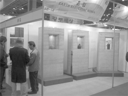
Stabilform thus provides an extremely low embodied energy component to the CO2 cost of each wall. There is no requirement for new formwork to be built for each new project. There are many sets of Stabilform in use in Australia, Thailand, Korea and the UK. The requirement to obtain a patent to construct the formwork has long gone, and credit must go to the system’s originator Giles Hohnen in conjunction with Perth-based fabricator Boyde Metal Industries. Giles is regarded as a generous pioneer of the SRE industry in Australia, along with other industry stalwarts such as Steven Dobson and Alan Brooks from Western Australia, Ian Collet from South Australia, Oliver Petrovik from Victoria and John Oliver from Queensland. All these practitioners have advanced the SRE industry in Australia through a lifetime of persistence and ingenuity.
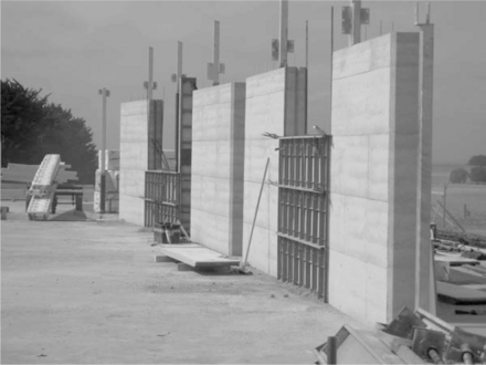
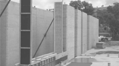
SRE walls are built as a series of monolithic panels. Each panel is constructed in situ. They are built allowing for control joints in longer panels at maximum 3800-mm intervals. Door and window openings are also used as control joints (see Fig. 22.2).
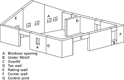
22.2 Typical SRE monolith panel layout describing control joint placement and the panel sections. Note: maximum length of panels between control joints is typically 4.0 m.
Formwork is erected along the very edge of the concrete raft slab or the concrete footing so water running down the face of the wall will flow over the concrete/wall joint without pooling.
22.4.1 Setting up
The ‘set-up’ involves selecting formwork lengths to suit the panel (forms have male–female sections for joining lengthways). Through-bolts are placed at 1000-mm intervals to restrain the compactive effort of the rammers. Shutters are clipped together using vice grip fasteners, the jaws of which can be opened or closed easily to secure various sections of formwork together. Thus a Stabilform set includes a bucket of up to 30 vice grips. End shutters are placed at the exact wall length position and the bolts are tightened using ratchet spanners against spacers to ensure the formwork is straight and plumb. Through-bolts are placed immediately behind each end shutter. Wedges between the bolts and end shutters keep them plumb while ramming. The end shutters are kept plumb on the sideways axis using extendable props that are secured to the head of the shutter and to the ground. These props can be wound in or out and locked off when the end shutter is true.
22.4.2 Corners
The Stabilform system uses specially fabricated 50 1500-mm-high steel sections, which interlock with the formwork to create either 90 or 45° inside or outside corners. The outside corner sections create a 50 mm chamfered edge, which matches the wall end chamfers. The inside corner sections create a square corner. Outside corners are propped to the ground to ensure they are built plumb.
22.4.3 Damp courses
An embossed plastic fabric damp course the exact width of the wall is cut to length. The damp course is then adhered to the concrete slab edge using a continuous polyurethane mastic bead. This prevents water ingress between the SRE-slab joint. Note that when detailing SRE, it is unwise to use a rebate in the concrete slab edge, otherwise common with block work or brick masonry.
A rebate takes the SRE below ground level or pavement level, thus exposing the base of the wall to potential ground water ingress (rising damp) thus compromising the effect of the damp course.
22.4.4 Key joints
The control joints at 3800-mm max intervals provide a partition line to prevent unsightly vertical shrinkage cracking, which can occur particularly in the event of prolonged hot weather or subsidence in the footing or slab. Each control joint requires a key to prevent panels from ‘tipping’ against each other. The key is created by nailing a 45-mm timber fillet with the hypotenuse side against the centre of the end shutter. When the end shutter is stripped away the reverse key is imprinted in the end of the wall (see Fig. 22.3).
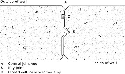
Before the adjacent wall is rammed against the key, a 20 75 mm closed cell foam weather strip is adhered to the full length of the outside edge of the wall end. This strip is extended down 50 mm beyond the base of the wall across the damp course of the adjacent wall. This ensures that rain driven into the control joint (which may have opened up to 10 mm due to shrinkage) runs down the closed cell foam strip and drains to the outside at the wall base. This detail is an important consideration especially as the walls have no rebate in the concrete to ensure water cannot penetrate to the inside.
22.4.5 Vertical chamfers
A 45-mm timber fillet is also nailed along each edge of the end shutter, providing a chamfer edge reveal to each wall end. The 45-mm fillet can be manufactured by ripping a 90 45-mm length of timber long-ways and then ripping the 45 45-mm section along the diagonal, a task most local timber joiners can do. Chamfers increase the beauty and function of an exposed wall end in a way a sharp-cornered brick wall cannot achieve.
Some practitioners use a smaller 19 mm fillet. From our experience we find the compactive effect of the round rammer head is greater using a larger fillet than a fine one.
22.4.6 Control joint appearance
In order to provide an attractive control joint, a 25-mm steel angle is placed open side out against the forms when the adjacent wall is rammed in place. This angle is taken away after stripping to reveal a vee-shaped control joint.
22.4.7 Blending of material
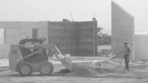
While the formwork is being set up, a ‘mix’ of materials is prepared for ramming. In Australia nearly every practitioner uses a skid-steer loader to blend the mix and then deliver the mix to the in situ formwork set-up. At the start of each project a ‘mixing pad’ of stabilised aggregate is laid down to provide a hard surface on which blending the material can be done without the risk of digging up surrounding ground that would contaminate the material. A section of flat ground preferably adjacent to the concrete slab and next to the aggregate stockpile is prepared for this purpose.
If the weather becomes inclement, the loader needs to be contained within the confines of the concrete slab and the mixing pad to avoid the tyres picking up surrounding clay lumps.
The loader operator batches out an amount of aggregate onto the centre of the pad. It is important the correct amount is batched to avoid blending too much stabilised earth. Mixes must be used within 1.5 hours, and less in warmer weather as the stabilising effect of the cement is drastically reduced after this time. Thus the team needs to establish how many lifts of the wall can be achieved in the following 1.5 hours and batch accordingly. The loader operator then places the required amount of cement bags on the pile and opens them carefully to ensure cement dust drifts away from them. The mix is blended by carefully turning the pile over and over using the loader until the mix is thoroughly blended (see Fig. 22.6). This normally takes 5 to 8 minutes depending on the size of the mix.
22.6 Blending and wetting the SRE material using a skidsteer loader. An average mix will take between 6 to 8 minutes to complete, including the blending of the Plasticure waterproofing admixture.
A second person then begins spraying the mix with water as it is turned using a high pressure spray nozzle. Good water pressure is essential – slow water delivery will lengthen the time taken to prepare the mix and thus shorten the time the mix is useful before it dehydrates. When the mix is partially damp – crumbly but not balling, the watering person prepares a container of diluted silane/siloxane waterproofing admixture to a volume according to the specification. This admixture is spread gradually through the mix using a watering can, all the while the material is continually turned by the loader. Finally, more water is sprayed onto the mix until the operator and the watering person are confident the correct moisture level has been achieved.
I will note here that some engineers have requested optimum moisture testing for every batch using scales to identify moisture levels by volume of material. By the time the test is satisfactorily achieved, the life of the batch is half over, especially on warmer days. The correct moisture level is such that optimum density can be achieved upon ramming the mix. Too wet and the rammers pug through the layer to be rammed. Too dry and the material fluffs around within the formwork and will not compact properly. It is as simple as that. It is experience only that guides the builders to achieve the correct moisture level. For an experienced team this important issue of correct moisture becomes second nature. Over-wet batches need to be discarded back to the stockpile and are thus a waste of material, time and money. A mix may need to be wetted down once or twice throughout its 1.5 hour life, after which it should be discarded back to the stockpile.
22.4.8 Ramming
Generally each 600 mm lift of Stabilform receives four 200-mm-deep layers of loose mix. Each 200-mm layer is compacted down to an average 150-mm layer. The material is delivered to the leading face of the formwork using the skidsteer loader, the bucket of which is lowered carefully so the rammer team can shovel the 200-mm layer without causing spillage outside the formwork cavity.
For a smoother wall surface the material is shovelled carefully against the formwork faces ensuring stones do not roll from the apex of the delivered material onto the wall surface. For a more textured outcome the material can be ‘pulled’ into the formwork cavity in which case small aggregates become part of the exposed wall surface.
The rammer team lift their pneumatic rammers into the cavity and compact the layer down to a hard and consistent level (see Fig. 22.7). The rammers must be kept upright and ensure the course is compacted evenly.
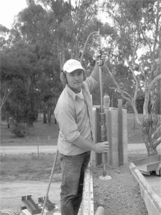
22.7 A pneumatic rammer. Note the access for the operator to the formwork and material. The actual ramming is the least physically demanding aspect of an SRE builder’s day.
Ramming a course of stabilised earth takes about two minutes per 2000-mm section of wall, normally about the time it takes for the loader to return with a fresh bucket of mix. The rammers can be easily lifted over the through-bolts (there is one bolt per 1000-mm length of 600-mm high formwork). Care is taken not to ram immediately on top of the through-bolts as bent bolts are difficult to retrieve the following day.
Good quality pneumatic rammers are comfortable to use. Most Australian teams use Ingersol Rand 341 model rammers or Chicago Pneumatic model CP 0003. Generally there are two rammers used consecutively to compact walls longer than 1800 mm or one rammer for walls shorter than 1800 mm. Corners need two rammers, one for each leg of the corner.
The final (fourth) course is achieved by heaping the mix 75 mm higher than the top edge of the formwork. The compacted final course is then level with the top of the formwork. The residue mix is swept away to reveal the female rebate ready to receive the next lift of formwork. The next 600-mm forms are lifted in place ensuring the vertical form-lines are staggered (see Fig. 22.8).
22.8 Placement of SRE formwork. Note the two consecutive ‘set-ups’ under construction by the one team. A team will typically build one or two complete panels per day.
The formwork is bolted together, the corners and end shutters are checked for level and adjusted if need be.
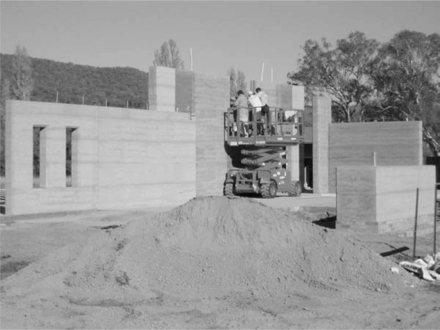
22.4.9 Scaffold
All wall building requires an efficient scaffold system to provide a safe and comfortable working platform at heights above 1800 mm. The Stabilform scaffold is integral to the formwork system and consists of support brackets that locate onto the ‘ramming’ side of the formwork. Handrails slot onto these brackets and two 250-mm-wide aluminium planks sit across the horizontal arms of the brackets. The system ensures the ramming team have close and safe access to the loader bucket, which approaches from the other side of the wall. At the same time they are not standing on top of the formwork or within the formwork, which would be unacceptable practice within the Australian building industry.
22.4.10 Electrical and hydraulic services
In most cases all electrical services are placed within the walls using 25-mm conduits that feed wiring to the roof space (see Fig. 22.9). Wiring and services fed from the base of the walls cause difficulties getting adequate and neat compaction to the underside of the service box. 25-mm PVC conduits are bent into shape using conduit springs (these avoid the ridged joins on manufactured corners bends that can frustrate electricians trying to push down their wiring). The conduits are attached to wall surface boxes onto which the light switches or power points can be attached at a later time. Shop drawings of each wall show the exact location of where services need to be located. The wall box with conduit attached is placed against the formwork face and fresh mix is placed immediately behind it. The mix is then compacted gently (to avoid dislodging the level of the box) using a small hand-operated rammer affectionately called ‘big foot’. Once the box is secure, the balance of the course of mix is placed and rammed. The rammers are designed to compact around the conduits.
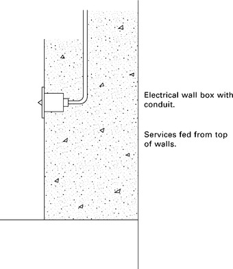
22.9 Electrical or data placement within a SRE wall. Cabling is generally fed from the top of the wall. Faces of the switches or power-points are screwed to the ‘wall boxes’ after the walls are completed and sealed.
Similarly, hydraulic pipes are placed and rammed within the wall. All hydraulic pipes must be lagged using a minimum of 20 mm foam lagging to prevent the potential for expansion cracking and piercing of the pipes by sharp aggregates during ramming.
In the event of meter boxes being required on an external wall, a polystyrene shape of the meter box is placed on top of the feeder conduits and more conduits rammed in place to take live wires to the rest of the building within the roof space. The polystyrene is later extracted and the meter box secured in its place.
22.4.11 Openings in walls
There are two ways to build window or door openings using the Stabilform system.
Block-out openings
In the event that a smaller opening is specified to be within the middle of a large panel (for example a bathroom window) it is better to use a ‘block-out’ form to create the opening shape. This block-out is made using 18-mm flooring sheet, which is fabricated in a way that while being strong enough to withstand the compaction of the rammers, it can be collapsed easily and re-used for other windows of the same size. Block-out openings need a minimum 500 mm SRE on either side of them to provide support.
22.10 A typical SRE ‘block-out’ opening. Note the adjacent opening has a control joint alongside it.
Control joint openings
Openings using a control joint system require a wall panel to be built up to each side of the doorway or window. Assuming the head height of the opening is 2400 mm, then key joints are cast into the wall heads on either side of the opening. A tee lintel or lintel rods are then bolted or sleeved into the walls on either side of the opening (see Fig. 22.11). A horizontal timber soffit is then positioned at the head height required between the opposing walls and held securely in place using wind-up props below. Formwork is then erected and bolted in place using the same chamfers, key joints and control joint details as described for standard panels. (For a full description of lintels and reinforced masonry lintels systems, see Chapter 18.)
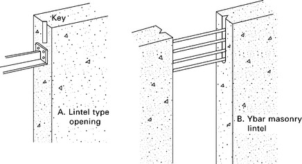
22.11 The steel tee-lintel system described on the left. The steel Y–bar masonry lintel system described on the right. For further descriptions of lintels and other structural steel elements, see Chapter 18 of this book.
22.4.12 Sills
Window sills are created by setting up formwork across the opening, using all the same waterproofing key-joint and control joint details as per a standard wall. The actual sill shape can be square edged, or a 45–mm chamfer, a 75–mm chamfer or a combination. Window frames can be set at any place within the opening.
We suggest using generous window sills on the inside (useful for leaving things on) and also ensuring the external sill is protected as much as possible by an overhanging window sill.
22.4.13 Stripping
Freshly rammed walls are left overnight to allow the stabilisers to harden sufficiently for the safe removal of the formwork. Stabilform through-bolts have a 19-mm hexagonal head on which 0.5 in. drive pneumatic rattle guns can be attached to ‘rattle’ out each bolt. Form lifts are removed layer by layer using straps wielded by the stripping team standing on the scaffold planks, or on high walls standing on a scissor-lift which is levelled at the top of the wall. The last four lifts can be stripped from the ground. An average 3000-mm-long 3000-mm-high wall takes 45 minutes to strip with forms stacked neatly on pallets ready for the next wall.
22.4.14 Plugging and detailing
The Stabilform system reveals bolt holes every 1000 mm or so at each 600-mm lift. These bolt holes are plugged using fresh sieved mix. The sieved mix can be pushed into the holes using small hand-held plugging devices and the convex mound left at the face of each hole is smacked flat to the wall surface with a hammer. Properly plugged holes cannot be identified on a wall surface among the regular bolt-hole ‘dots’ that appear at 100-mm intervals. The appearance of these plugged holes has never been an issue for Australian architects.
In some cases there may be small fins of SRE that stay on the wall surface between form joints. These are removed immediately after stripping using a small trowel.
22.4.15 Visual features of stabilform
An SRE wall built using Stabilform is easily identified by the 600-mm horizontal form lines and the bolt-hole ‘dots’. These features can be minimised by dressing the walls carefully following stripping. However, many Australian, UK and South Korean architects enjoy the ‘signature’ of these lines and believe that leaving the features expressed adds to the honesty of the structure.
22.4.16 Internal sealing
Once the wall surfaces have properly dried, usually a month or so after the last wall is completed depending on the air temperature, a surface sealer is applied to bind any loose particles that may brush away over the years into the wall substrate. Diluted acrylic binder is applied to the internal wall surfaces using thick-nap roller heads. Care is taken not to seal any external wall surfaces as the binder will prevent moisture from evaporating properly from the external wall surface over the ensuing years. This can result in the face of the wall ‘spalling’ away as the moisture trapped within the wall pushes the bound surface off as it tries to evaporate. The surface hardness of the walls is more than sufficient to resist driving rain and the normal wear and tear of a wall surface.
22.4.17 Capping of the parapet and landscape walls
As with all masonry including brickwork, all parapet walls subject to weather require protection with either a folded metal or a cement render capping (see Fig. 2.13).
2.13 Cement render wall capping. Note the 18 mm overhang to disperse rain water to prevent streaking. Mansfield Golf Club entry, Victoria.
Note: We discourage using pavers or tiles, as the joints between these can grow mould during warmer wetter seasons, which then runs down the face of the wall causing unsightly marks.
22.4.18 Fixing to SRE
Light loads such as timber wall frames attached to the SRE can be held in place and either nailed using nail guns or bolted using 10-mm expansion bolts at 900-mm centres. Heavy point loads such as verandah beams, roof plates, floor beams, etc. need to be fastened using a polyester chemical injection anchor system (e.g. Ramset Chemset 101) with 12-mm bolts embedded a minimum of 200 mm at 900-mm centres. Ensure bolts are a minimum of 200 mm from wall ends, control joints or wall heads.
22.4.19 Machinery
The stabilform system requires two items of heavy machinery. Firstly a skidsteer loader (minimum 50 horse power) with a forklift attachment and standard earth bucket. secondly a 100 cubic feet per minute air-compressor, usually mounted on skids so it can be transported easily as part of a single flat-bed truck load. The skid-steer loader has three main tasks. One is to batch and blend the base materials. The second is to deliver and elevate the fresh mix to the wall under construction. The third is to load and unload the formwork cages from the delivery truck and to then move pallets of formwork about the site.
The air-compressor has two tasks. One is to power the pneumatic rammers and the second is to power the pneumatic rattle gun used for stripping the through-bolts out of the walls each morning.
Both machines use on average 25 litres of fuel each day combined.
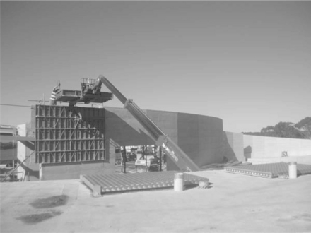
For walls over 3.6 m height, it is necessary to elevate both formwork and the blended mix safely and efficiently. In most cases an all-terrain scissor-lift is used to elevate formwork and staff to one side of each wall (see Fig. 22.14). In some cases telescopic handlers can deliver material to the wall face (see Fig. 22.15). Material delivery to the other wall face is best achieved using a telescopic handler with a standard earth bucket. The skid-steer loader fills this bucket which is then lifted quickly by the telescopic handler to be placed within the formwork cavity. in some cases walls as high as 12 m have been built using this system. Telescopic handlers provide a surprisingly stable material delivery system.
22.5 Stabilised rammed earth (SRE) walls
22.5.1 Insulated walls
The Victorian 5 star energy rating (ref Building Commission of Victoria practice notes, 2007, 55) required all external walling for residences to have a minimal thermal resistance performance (R value i.e. m2 k/w) rating of 2.0. The performance of a 93-mm-thick SRE panel, with a density of 2118 kg2 m3 submitted for testing by Earth structures Australia Pty Ltd in 2004 gave a thermal resistance result of 0.084 m2 k/w. Thus a 300-mm SRE wall had an R value rate of 0.252 assuming the rate of temperature passage through 300 mm of wall would be sustained at the same rate as for the 93-mm test sample.
Earth structures Europe had previously developed an insulation system for SRE walling in the UK where long cold winters dictated high R value ratings for all external walling. This system was adapted by Earth structures for Australian conditions using a 50-mm styrofoam barrier sandwiched between two layers of 175-mm-thick SRE giving an R value result of 2.46 m2 k/w7 (see Fig. 22.16).
22.16 An insulated wall set up and ready for ramming. Note the material used for this project was a blend of recycled concrete and local aggregate resulting in a very low embodied energy. Berkeley residence, Thornton Victoria.
The system (commonly referred to as ISE – insulated stabilised earth) uses 280-mm-long 8-mm stainless steel bridging pins with 50-mm cob ends installed at 600-mm vertical and horizontal spacings. These pins provide the wall with tensile load resistance both under compression and tension, sufficient for walls up to 4.2 m heights stand-alone, and 8.4 m heights using embedded steel portal frame structures.
The ISE system, in conjunction with Stabilform formwork keeps a 150-mm solid section of wall adjacent to door and window openings to provide secure fixing. In the colder UK, however, the ISE system continues right to the wall ends where inverted fixing channels are incorporated into the end shutters.
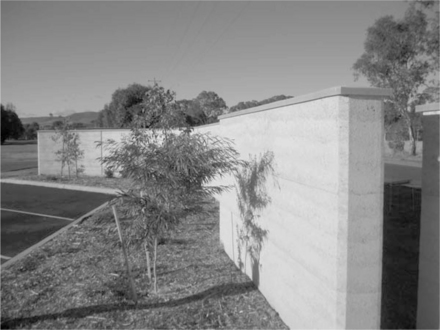
22.5.2 Landscape walls
Landscape or garden walls require special design considerations to ensure they remain dry and stable. If used as a retaining wall, the face of any SRE subject to groundwater ingress requires thorough tanking with polyurethane or bituminous paint, then properly jointed membranes to resist scoring by sharp aggregates.
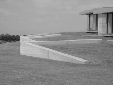
Finally the base of retaining walls requires proper drainage to ensure water-logged back-fill does not overload the designed tipping resistance of the wall (see Fig. 22.18).
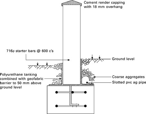
22.18 This diagram describes the minimum protection required for landscape walling. Note ground barriers must extend 50 mm above the surrounding lawn or garden bed. Inevitably, beds and lawns ‘grow’ and walls must remain protected from the effects of rising damp.
To provide further resistance to tipping there may be a requirement to incorporate vertical steel starter bars within the wall. Ensure these bars do not exceed one-third of the wall height, as this leads to horizontal shrinkage cracking caused by the drying walls lifting themselves up along the length of the steel bars. Any vertical steel reinforcement must be galvanised to prevent the steel from rusting and causing pressure spalling decades later. All landscape walls require a cement render capping system that ensures rainwater is cast well away from the top edge of the wall to prevent staining marks down the surface.
22.5.3 Elevated walls
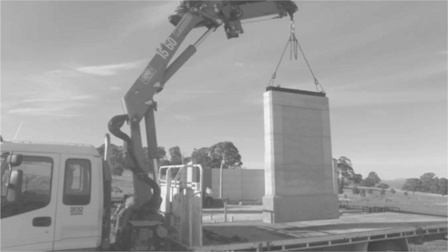
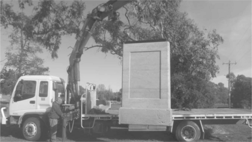
In the event an architect requires SRE walls to clad an otherwise inaccessible building face, Earth structures have designed systems of ‘pre-cast’ walling. These SRE panels are built off site or nearby with steel lifting lugs incorporated into the wall heads so they can be elevated in place using overhead cranes. The largest panels built using this system were 4.8 m high 3.2 m long and 300 mm thick (see Fig. 22.19).
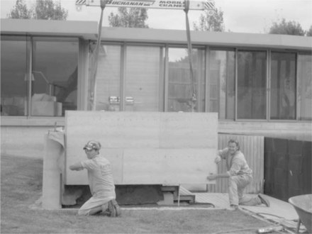
We have also built large corner-shaped panels, which are lifted using specially designed spreader bars to resist the lifting loads being transferred into the wall structure. Ferrules can be cast into the wall face to allow the bases or sides of the walls to be fastened onto a portal frame. Small uses of these walls also include entry walls for housing estates, entry walls for cities, entry gates for rural properties and advisory sign walls for municipal shires. These smaller walls can be rammed directly onto a cast concrete footing to the entire footing/SRE wall package. They are then lifted and transported using a crane truck then lowered into an excavated trench and backfilled (see Fig. 22.20). This practice saves the cost and inconvenience of transporting an entire SRE team to a remote place for one or two small walls.
22.6 Designing for thermal comfort
22.6.1 Passive solar design
The Australian temperate climate zone provides an ideal environment for the sensible use of SRE. We have long summer high day-time temperatures followed by cool night-time temperatures. We also experience relatively short winters with enough cloudless days to provide warming day-time sunlight. Good design can harness these climatic circumstances using solid masonry walling. Most Australian architects and designers are aware of passive solar design. I don’t intend to describe the theories of passive solar design in this chapter except to outline some peculiarly Australian design ideas that have proven over the decades to provide comfortable and low operational cost living conditions.
22.6.2 Orientation of the building and layout of the rooms
Australian winter sun tracks low across the northern sky. To ensure maximum use of this warming winter sun well-designed buildings have large openings to the north. It is preferable to have daytime-occupied rooms benefit from this winter sun. Thus kitchens, living rooms, offices and children’s play rooms are best positioned along the north side of the house.
Bedrooms can, in our humble opinion, remain cold. That’s where one goes at night, and that’s what good thick eiderdowns are for.
To maximise the effect of winter sun beating into these north-orientated rooms, concrete or masonry floors serve to retain the heat at night as well as reflecting sunlight well into the room to warm the interior masonry wall surfaces. Window and door openings need to be covered during winter nights with curtains or shutters thick enough to provide an insulative effect. Double glazed windows are now required in most temperate zones in Australia.
22.6.3 Shading of windows in summer
Australian summer sun tracks virtually directly overhead. However it is wise to have narrow eaves along the northern openings to prevent hot sun from shining into the rooms in the heat of the day. These eaves need only be 900 mm wide to shade these openings. West facing windows-which are prone to long hours of afternoon sun, need to be either omitted or kept as small as possible. Ideally a good house design includes substantial shading from leafy trees to the west of the building or, failing that, substantial verandahs on the west that provide deep shade throughout the afternoon.
22.6.4 Natural ventilation
Sitting in a room on a hot day with a gentle breeze flowing through the room provides a welcome cooling sensation. The ability of openings to capture breezes to flush air throughout a building is a vital part of good design. Rooms that have openings along opposing walls allow for a direct flow of air across the room and out the other side. Buildings built as one large square with openings on one side of each room only have less chance for through-ventilation to happen. Casement windows have the ability to catch and redirect breezes into a room more than sash windows do. For this reason casement windows are increasingly popular as tools for passive ventilation.
22.6.5 Managing the thermal benefits
There are passive solar benefits of living in solid masonry buildings. However they must be managed in order to make them work. For summer conditions, the building must be opened in the evening to allow as much cool night air to flow through the rooms as possible. During summer days, if the house is unoccupied, these same openings need to be closed at daybreak (or as soon as the daytime temperature starts to rise) and curtains/shutters drawn to keep the night time ‘coolth’ within the confines of the building. If the house is occupied during a summer day the occupant may want to open strategic windows to allow breezes to flow across the room.
The reverse needs to happen in winter. Openings must allow winter sun to shine in from the north and should be closed in the evenings to keep as much of the trapped thermal heat in during the night. This system of managing openings also suits the mental comfort of most occupants. On fiercely sunny summer days, it is pleasant to be within the cool and shaded interior of a solid building. Conversely, in winter one wants as much light about the house as possible. A badly managed solid masonry house that is not given the chance to cool down from inside during summer will eventually heat up and become uncomfortable, especially during our Australian summers. All buildings, lightweight or solid, will become cold if they are mismanaged during winter.
22.6.6 Building codes and thermal comfort
Contemporary Australians have far higher demands of thermal comfort than previous generations. There is an expectation that room temperatures remain at constantly cool levels in summer and warm levels in winter to a degree that mechanical air conditioning is a given staple of modern Australian housing.
Most building design codes in Australia consequently assume that mechanical heating and cooling will be used for most of the day throughout summer and winter.8 Due to this assumption, our current building energy rating systems do not take into account much in the way of passive heating or cooling. Therefore most recent Australian building energy rating systems (5 star energy ratings) require all walls to have high levels of insulation to keep this manufactured air temperature intact within the building envelope for as long as possible.
For some time the new energy rating system did not allow for un-insulated solid masonry walling at all. The earth wall industry in Australia was facing closure, and in many cases the effect was severe downturns in the work for contractors, especially in the mud brick industry where insulation systems have been difficult to achieve.
some recent adjustments to the computer modelling that drive the energy rating systems have allowed certain variables (such as increased roofing insulation in lieu of reduced wall insulation) to occur. Upgraded energy rating systems that take into account passive solar benefits are being developed and will help alleviate what has been simplistic computer modelling based on insulation alone as a means of reducing energy use in a building’s life cycle.
22.6.7 House size
Perhaps the greatest failing of Australian housing over the past five decades has been the four-fold increase in house occupancy space per individual.9 This is due to an actual increase in house size (up 200% since 1960) and the decrease in the number of occupants within individual houses (down 200% since 1960). The environmental consequence of this trend is staggering given increasing population levels. Apart from the increase in heating and cooling that big houses create, they also inevitably fill with consumables, which would not be required with a smaller house. The financial debt required for larger houses and increased volume of consumables then tends to add to the workload and anxiety of the occupants, which decreases the value of family life considerably. No end of using low embodied energy materials such as SRE walls can balance the environmental impact of designing large houses.
In some cases the environmental benefits of using earth walls and other green technologies can be used by designers and clients as a rationale to justify building larger houses. For our society to get serious about the environmental impact of humanity on all levels, one simple, easy, but overlooked way to reduce this impact is to reduce the size of our buildings.
22.6.8 SRE as fire protection
The February 2009 devastating bush fires in Victoria brought immediate and thorough upgrades to the Victorian building codes to deal with rebuilding in bushfire-prone areas. These codes are based on an assessment of the building site to ascertain what degree of exposure the new building will have in the event of a bushfire. The assessments are called BALs, Bushfire Attack Levels.10 The most severe cases require buildings to be clad using fire-proof materials that have in excess of a four-hour fire rating including steel sheet, fired masonry and SRE.
22.7 Standards and specifications for modern earth construction in Australia
22.7.1 Building standards
The Australian building industry is regulated by the Building Code of Australia, which applies standards for the various building trades. These standards are updated on a regular basis as new technologies arise or building conditions change. For example, an environmental expectation may emerge that requires a trade to upgrade its performance. The Building Code of Australia has until recently assumed as its earth building standard a reference to ‘CSIRO EBS Bulletin 5’, which was derived from Middleton’s experimental work in the 1940s. This reference has become increasingly redundant in the light of testing and experience available from the last 30 years’ work.11
In 2008 the CSIRO removed Bulletin 5 as an obsolete reference document. The EBAA (Earth Building Association of Australia) is currently developing a replacement document, though it is not yet suitable for use in the Building Code of Australia.12 In the meantime the earth wall industry has been required to use alternative means of self regulation, more often than not reverting to CSIRO Bulletin 5 as a fallback ‘deemed to satisfy’ document.
22.7.2 Specifications
Most Australian designers and engineers also use specifications as part of their documentation for drawings submitted for tendering by builders. These specifications ensure buildings are constructed and finished in a manner and to a level of acceptability that will satisfy the designer and engineer. Many Australian designers and engineers currently use the Natspec Specification for Monolithic stabilised Earth Walling section 02350 (2004).13 This specification is advised by the results of testing and decades of experience by ASEG (Affiliated Stabilised Earth Group) of which over 14 SRE companies in Australia, the UK and south Korea are members.14 This specification is attached to the subcontract tender documentation and ensures elements of the trade such as materials selection, sample testing, tolerances and finishes are upheld by the SRE operator.
22.8 The cost of stabilised rammed earth (SRE) construction in Australia
The cost of SRE in Australia varies enormously according to the design of the building, the location, access and the industrial conditions of the site.
The cost for most solid masonry including double brick, core-filled and rendered concrete blockwork, double-sided stone work and mud brick are all in the same cost ball-park.
Generally the cost of 300-mm-thick walls for domestic building is AUs $350 to $450 per m2, increasing if walls are over 3 m is height. Four hundred-millimetre-thick insulated walls are approximately 20% more expensive than the standard 300 mm walls. simple shaped buildings with long runs of straight walls and minimal returns or ‘nibs’ can be built more cheaply than complicated structures. Commercial sites attract a far higher premium due to site issues such as higher wage agreements, portal steel reinforcement for high walls, stringent safety procedures and industrial delays. A typical cost allowance for walls exceeding 6-m heights on a commercial site can exceed $850 per m2 for 400-mm-thick SRE walls.15
22.8.1 Business models
The SRE industry in Australia is best described as an amalgam of small individually owned and operated companies. In some cases an operator may end up with two or more sets of equipment, however, it is patently obvious that the industry works best as smaller owner-operator companies. Competition is strong between these companies, however, in some cases a truce flag may be raised in order to combine forces to construct projects otherwise too large for one operator.
An interesting affiliation of small operators was formed by Giles Hohnen in the early 1990s in an attempt to enable serious self regulation and the sharing of ideas. Giles quickly advanced the industry to a high level of acceptance by the market and regulators. From this affiliation (Affiliated stabilised Earth Group – or ASEG) over 14 companies were launched and still operate today. The group collated information and testing results for hundreds of issues relating to formwork, structural engineering, soil mechanics and marketing.
Australia is a vast country and an SRE operator inevitably travels far and wide to maintain a steady flow of work. The actual work is labour intensive but immensely satisfying. Few occupations bear such immediate and gratifying results as turning piles of earth into beautiful structures, often in remote and lovely settings. There is also the argument that the sort of people wanting to live in earth houses are better to deal with than most. This is an absurd assumption but we believe it!
The Earth Structures Group is a further extension of the ASEG model with companies sharing ideas, staff, marketing costs and group buying. The group combines on occasions where projects are too large for one company to deal with.
22.9 Case studies of modern earth buildings in Victoria, Australia
22.9.1 Contemporary insulated residential buildings
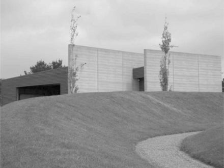
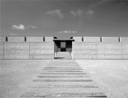
Swaney House, Flinders
Simon Swaney, a Sydney-based architect, has designed and built a simple SRE beach house for his family near Flinders on the Mornington Peninsula, one hour’s drive south from Melbourne. The house comprises two significant facet-curving earth walls. The first is a 400-mm-thick 2100-mm-high solid SRE wall that acts as protection screen between the driveway and the entry of the house. The second is a 400-mm-thick 3300-mm-high ISE blade wall, which dissects the house at various intervals but acts as a west-facing external wall (thus the ISE). This same wall runs out into a coastal landscape at either end of the house.
To quote an article by Francesca Black in Issue 46 of the residential houses magazine Houses:
On arrival the visitor is met with the sweeping curve of a massive rammed earth wall in the lee of the building. Presented in a refreshingly unpretentious manner, the austere beauty of the material speaks for itself. This wall is offset by an even larger rammed earth wall behind, the space in between forming a secluded courtyard. The second wall forms a central spine to the building. This weighty element serves to ground the house. With its sculptural qualities, striations of texture and rich, honeyed tones, rammed earth has been used here to great effect.
The great effect is also due to the simplicity of the wall shape. These are long, elegant and massive walls, which the designer has chosen not to play around with.
22.9.2 Large commercial and public buildings
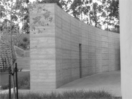
Port Phillip Estate Winery, Red Hill16
Wood Marsh Architects are a Melbourne-based firm specialising in urban design and major public infrastructure. The Port Phillip Estate Winery is a large wine production, restaurant and wine museum facility near Red Hill, one hour’s drive south from Melbourne. The building was constructed using a portal steel frame clad with 400-mm-thick SRE facet-curving panels that flow from one end of the building to the other. There are few openings in the walls which add to the dramatic effect of their mass. The staircase from the restaurant to the barrel store has visitors descending between two rammed earth walls as high as 12.6 m.
The material for the walls was sourced from a local sandstone base quarry producing a soft grey effect. The wall colour alters with the changing light of the day to produce vibrantly warm early morning and evening hues to stark grey walls at the height of a summer day.
To quote from the Australian Institute of Architecture jury who awarded the building the sir Osborn McCutcheon award for commercial architecture (2010):

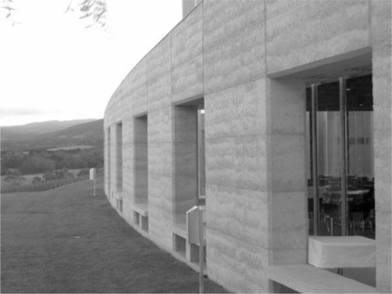
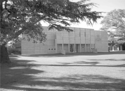
Tarrawarra Museum of Modern Art, Healesville
Alan Powell is a Melbourne-based architect who won the competition to design this museum for Australia’s largest private modern art collection. The building required strong natural elements. SRE was chosen for its simple, rugged form in what is an elegantly shaped structure. The museum has become a much loved icon of Australian modern art and a popular weekend retreat for the Melbourne art crowd.
The SRE walls are a blend of a rocky over-burden from a quarry near Seymour, 100 km from the site. The base material was blended with sand to bring the mix within the confines of the specification. To retain the boney appearance the SRE teams ‘pulled’ the material into the formwork thus allowing larger aggregates to fall towards the face of the formwork prior to ramming. The long curves were created using specialised adjustable-radius formworks which were clipped to curving steel templates to achieve the uniform shape. Large ‘masonry lintel’ openings were achieved using steel hoops attached to 16-mm dowels bolted to the SRE panels on either side.
22.9.3 Precast and elevated modern earth structures
Lauriston Science and Resource Centre, Armadale
This building was designed by Melbourne firm Swaney Draper Architects with a brief to use a huge effort towards environmentally sustainable materials. The rammed earth walling used was a blend of recycled crushed brick rubble and locally quarried red sand. Seven SRE panels were required to be suspended between steel posts along the front of the building. These 4.8-m-high, 3.2-m-long panels were constructed nearby within the building site on temporary concrete plinths and later elevated using the overhead crane on site. Once located the panels were bolted to cleats extending from the steel posts and to the concrete slab structure immediately behind the walls. The walls contained steel ‘lifting rod’ U-shaped sections, which were rammed within the panels. The spreader bars were located over threaded bolts welded to the tops of these steel sections. The steel ‘lifting rods’ were housed within plastic conduits to prevent the walls shrinking along the length of the rods.
Mansfield Shire information wall, Mansfield
This small 300-mm-thick sign wall to a public area was made affordable by pre-ramming the wall onto a pre-cast concrete footing at a nearby building site where local rammed earth contractors were building a house. The entire wall/footing was then lifted onto the bed of a crane truck and transported to the site where a level based trench had been dug. The wall was lowered into the trench and settled on a bed of concrete to seat the structure. The sides of the trench were backfilled and tamped to ensure the wall remained plumb. This system saved delivering soil and formwork to the remote site, making a mess with the mixing pad for blending the material and then freighting out again.
The wall was lifted using a 16 mm U bar cast initially within 100-mm of the base of the concrete footing. Once the wall was in place the tops of the lifting bars were cut off and a protective cement cap cast along the top of the wall.
22.10 Future trends
The progress made so far in modern earth building in Australasia has been due to a combination of architects and designers willing to advance sensible eduction for sustainable development (ESD) using earth walling together with a committed SRE construction industry.
Since the advent of SRE in Australia as a serious industry in the early 1980s there have been in excess of 4500 domestic and 300 commercial projects completed. This is a conservative estimate as many early contractors have not kept decent records of their achievements.
As a product, SRE is becoming more mainstream and considered less ‘herbal’ than it may have two decades ago. Most people in southern Australia have seen a building made using SRE, usually a public school, winery or municipal structure, if not in real life then in some glossy architectural magazine, which seem to feature SRE buildings by the week.
No one company has trumped the industry in terms of patents or market dominance, which all Australian SRE operators believe will lead to a better future for the industry.
There is a strong commitment within the Australian industry to embrace competition, which inevitably results in higher standards and a faster improvement of construction systems.
Larger commercial projects push the boundaries of the product in terms of construction speed, safety and structural difficulty, all of which result in technical advances that trickle down into the mainstream building of SRE walls.
Globally there is an increasing demand for SRE technology, particularly in countries with enough capital to fund the gear and machinery to get started. The Earth Structures Group as an example work as consultants for projects in Thailand, South Korea, the UK, the USA and Africa. In cases where the technologies are useful the group will establish long-term affiliations with overseas companies in order to share and develop ideas and systems.
22.11 Sources of further information
Domestic
1. Merricks North House, Wood Marsh Architects, Melbourne www.woodmarsh.com.au/projects/detail/merricks_north_house/
2. Dromana, Vine House, John Wardle Architects, Melbourne www.johnwardlearchitects.com/projects/default.htm?i_PageNo=1&Proj ectId = 3&pageNo = 1&ProjectCategoryId = 0&ProjectKindId = 0&Featured = 0&Archived = 0&AllProjects = 0
3. Red Hill House, Gregory Burgess Architects, Melbourne www.gregoryburgessarchitects.com.au/projects/1994/earth-house/
4. Injidup Residence, Wright Feldhusen Architects, Perth www.wrightfeldhusen.com/index.html
5. Shenton Park Residence, Wright Feldhusen Architects www.wrightfeldhusen.com/index.html
6. Dunsborough Residence, Wright Feldhusen Architects, Perth www.wrightfeldhusen.com/index.html
7. Yallingup House, Hofman and Brown Architects, Perth www.hofmanandbrown.com.au/index.php?id=112.
Commercial
1. Mansfield High Country Visitor Centre, Gregory Burgess Architects, Melbourne www.gregoryburgessarchitects.com.au/projects/2003/high-country-visitor-centre/
2. Hillview Quarry Offices H2O Architects, Melbourne www.h2oarchitects.com.au/
3. Twelve Apostles Centre, Gregory Burgess Architects, Melbourne www.gregoryburgessarchitects.com.au/projects/1999/twelve-apostles-visitor-centre/
4. Charles Sturt University, Marci Webster-Mannison Architect, Brisbane www.rivertime.org/lindsay/ar_articles/ar_73. pdf
5. Tarrawarra Museum of Modern Art, Alan Powell Architect www.probuild.com.au/projects/tarrawarra-museum-of-art/.
22.12 Acknowledgements
The author would like to thank the following for their help and ideas in preparing this chapter. Brad Overson, Scott Kinsmore and Ben Taylor of the Earth Structures Group, Simon Swaney of Bates Smart Architects, Giles Hohnen, Alan Brooks, Steven Dobson, Howard Marshall and Charlotte Lindsay.
22.13 References
1. Australian Bureau of Statistics, 2009. abs.gov.au
2. Kneeler Design Architects (kneelerdesign.com.au)
3. Boral Stoneyfell Quarry, Adelaide (boral.com.au)
4. Aidan Graham Quarry, Langwarrin
5. Rammed Earth Constructions (rammedearthconstructions.com.au)
6. Techdry Plasticure (techdry.com.au)
7. CSIRO test MSQ – 1530, 2004. [March].
8. Sustainability Victoria – 5 Star Rating notes (sustainability.vic.gov.au)
9. Australian Bureau of Statistics, 2009. abs.com.au
10. CFA Bushfire notes (cfa.org.au)
11. ASEG notes (aseg.net)
12. South Australian Govt earth building regulation notes (sa.gov.au)Also(ebaa.org.au)
13. Natspec 02350 (natspec.gov.au)
14. Affiliated Earth Structures Group (aseg.net)
15. For detailed QS notes (rawlinsons.com.au)
16. Port Phillip Estate Winery (portphillipestate.com.au)