
Fabric insulation, thermal bridging and acoustics in modern earth buildings
Abstract:
Buildings account for nearly 40% of the energy consumption in the UK, producing almost half of the CO2 emissions at a national level. Using appropriate insulation is a cost-effective way to substantially improve the energy efficiency of any building and reduce the overall contribution to global CO2 emissions. This chapter focuses on cavity insulation with an overview of insulation material types and physical properties. Examples of cross-sectional construction detailing for typical stabilised rammed earth (SRE) cavity walls are given. It also provides an insight into established research of 2D and 3D modelling of thermal bridges, and the relevance of acoustic properties in relation to thermal mass. Finally, the more widely available software products for both acoustic and thermal bridge simulation are evaluated and summarised.
3.1 Introduction
In a global market where future energy may be substantially more expensive, guidance for the Architecture, engineering and Construction industry (AEC) will be increasingly important both for refurbishment and new build. Appropriate insulation for instance will significantly decrease the energy demand of a building and will thereby play a central role in reducing global CO2 emissions. This chapter summarises different approaches to the fabric insulation of modern earth buildings by addressing the different issues one has to face in terms of acoustic and thermal behaviour. Acoustic isolation of a building is very important in terms of achieving occupant comfort, in addition to the temperature, humidity and air quality. Research addressing thermal bridges is also particularly relevant in this context, as these account for a significant proportion of heat loss in buildings; providing the potential to dramatically decrease the energy demand.
Current environmental issues call for urgent changes to the way in which buildings are thermally designed. At present, commercial, residential and industrial buildings use nearly 40% of the energy in the UK, producing almost half of the CO2 emissions at a national scale; 55–60% of this energy is used for heating and cooling of the premises; the rest is consumed by electrical appliances, lighting and other uses (Department of Trade and Industry, 2001). If change is to be undertaken, a reasonable focus should lie on the thermal insulation and reduction of unwanted thermal losses and gains through the outer envelope of buildings. Proper thermal design is an essential step to ensure significant improvements in a building’s overall energy performance. Using appropriate insulation is one of the most straightforward options for substantially improving the operational energy efficiency of any building and thereby reducing its contribution to global CO2 emissions. Targeting nearzero heat losses can dramatically decrease the energy demand and contribute to a greener and more sustainable environment, whilst simultaneously improving the thermal comfort of the occupants. Although material selection is important, achieving the correct level of construction detailing is perhaps the most essential factor during the design and installation of building fabric insulation. Without careful consideration of the positioning, thickness and continuity of insulation a building can inherit one or more performance defects such as interstitial condensation (i.e. within the wall fabric), thermal bridging and isolation of thermal and/or hygric mass. These can impact on both the operational energy efficiency and also the health and comfort of the occupants. A responsible approach in planning new buildings might be the key to guaranteeing the future of upcoming generations (Hipworth, 2011).
3.2 Approaches to fabric insulation
Conventionally, insulation is placed in one of three different locations: (i) internally towards the building’s interior; (ii) externally, on the outside of the building shell; or (iii) in between the building’s outer and inner layer known as cavity insulation. Less commonly, insulation may be located in multiple layers throughout a construction, or comprise the entirety of the construction, however these rarely used solutions will not be discussed here as they do not apply to earth wall construction techniques. Obviously, there are a number of advantages and drawbacks associated with each of the insulation techniques. For example, in the context of heritage buildings where one has to protect the outer appearance of the building, most probably internal insulation will provide the only acceptable solution to planning authorities.
Regardless of whether the building is insulated during the building process or after the building is built, the insulation specification is ultimately a compromise between what is actually possible (e.g. feasibility, investment costs, legislation and norms), what is comfortable (i.e. heat and moisture, acoustics behaviour, thermal comfort and health-related issues, etc.) and the actual savings in terms of operational costs. According to Standards New Zealand (1998), in the absence of laboratory test data the total thermal resistivity (RT) of a stabilised rammed earth (SRE) wall, of thickness d (m), can be calculated as shown by equation 3.1.
The Building Regulations and minimum value of thermal resistance that is required vary according explicitly to the country/region in which planning consent is being sought, and implicitly by the ambient climate. The client/designer may wish to exceed these minimum requirements if they are seeking to achieve a greater level of thermal resistance and associated reductions in building energy consumption. This could simply be an aspirational R-value, one determined as the product of building performance simulation, or it could be set by a voluntary ‘best practice’ scheme of accreditation, e.g. BREEAM in UK, LEED in US, CASBEE in Japan, MINERGIE in Switzerland or the passivHaus standard in Germany, etc. In England and Wales (UK), for example, wall fabric may comply with the Building Regulations if it has a total R-value of the order 2.85 m2 K/W. By means of comparison for a warmer climate, to achieve a ‘5 Star’ energy efficiency rating (i.e. ‘high’, on a scale from 2 to 6 stars) under the non-compulsory Australian system (equivalent to BREEAM in the UK), an R-value of 2.2 m2 K/W would be required, whilst under the German passivHaus standard (a non-compulsory, best-practice design code – Chapter 5) an R-value of between 5.0 and 10.0 m2 K/W is needed (Schnieders, 2009). Clearly, in climates where there is a significant heating load and a cold season, even the minimum R-value requirements cannot easily be met by an earth wall without insulation. The placement and installation detailing of insulation materials is discussed in the following sections, as well as details of the insulation material types that could be used with SRE walls along with details of their physical properties.
3.2.1 External wall insulation
Insulating the building externally decreases the possibility of thermal bridges. These are local regions of the earth wall (or adjoined structure/feature) in which heat transport is comparatively high and any applied insulation is ineffective. Thermal bridges can either be physical (e.g. where an uninsulated steel lintel conducts heat and bypasses the insulation) or geometric (e.g. on wall corners where the external surface area is greater than the internal). Thermal bridging is discussed in detail in Section 3.4. Furthermore when the insulation is located to the outside of a building’s load-bearing wall, the structural components are better protected from extreme temperature variations and condensation risk. This reduces the possibility of damage due to thermal stress and water vapour saturation (Krus et al., 2005).
The thermal storage capacity is also improved by external insulation in heavyweight structures, especially in modern earth buildings or in reinforced concrete structures where stored heat is less able to transport through the wall and escape to the outdoor environment. One effect of this is that external insulation will limit the overheating frequency during hot summer months, since the wall fabric is not heated by external gains and is therefore more able to absorb excess internal heat gains. Where the insulation is external, it needs to also protect the building fabric from the influences of rain ingress and wind; unless the structure is overclad with a rain screen. This leads to the necessity of using water-resistant renders over external insulation and normally comprises a proprietary system.
Due to the external exposure of the water-repellent plaster, which is thermally decoupled from the load-bearing wall by the insulating material, it must resist high temperature variations. These variations are a consequence of diurnal temperature variation, wind exposure and long wave radiant heat gains and losses. On clear nights, the external boundary layer will typically be below the dewpoint temperature which leads to a high risk of condensation and potentially mould growth. In terms of applying external insulation to an existing building, one will face relatively high installation costs where scaffolding is necessary. External insulation can change the building’s appearance, to the point where it may become unsympathetic to the local character, whilst in some cases also increasing the building’s footprint. SRE walls do not require protection from the weather and, due to their attractive sedimentary appearance and natural earthen colour, the external aesthetics form part of the appeal to designers and clients. For this reason, external insulation is generally not favoured and cavity insulation is used instead (see below). Unstabilised rammed earth, however, does need to be protected from the outdoor environment and so, despite the significant extra costs, protective waterproof external render systems can be applied that also incorporate the desired level of insulation. Similarly, rain skin cladding or double skin façades can also be applied in this situation.
3.2.2 Internal wall insulation
Internal insulation is often the most viable in terms of costs when insulating a building retrospectively, because this method is relatively easy to apply and does not require additional weather protective coverings. It is often the best thermal solution for buildings that are of masonry construction in colder climates and only used intermittently as it reduces the re-warming time by reducing the thermal admittance of the internal surfaces. Using this approach a room can be heated fairly quickly as the external wall layer does not need to be heated in order to achieve a satisfactory operative temperature. Compared to external insulation or cavity wall insulation (Section 3.2.3), this method is least desirable in modern earth buildings or in reinforced concrete structures in hot climates where the internal insulation will decouple the thermal mass of the building and therefore not contribute to lowering the overheating frequency. An exception to this occurs where adequate thermally massive internal (e.g. partition) walls, or dense large floor slabs and exposed concrete soffits/upper floors, are available to dampen the diurnal temperature swing.
The usage of internal insulation is less appropriate in terms of fire protection where flammable and toxic insulation materials are used, such as those that are based on organic foams such as polystyrene or polyurethane (Krus et al., 2005). In high-density urban locations, where ground is expensive, the reduction of the treated floor area through the use of internal insulation is another drawback. The practical problems associated with relocating occupants are another issue that is often overlooked during the retrospective installation of internal insulation. However, the biggest technical problems one will face with internal insulation are related to the occurrence of thermal bridges, condensation risks and the reduced possibilities for drying out of the load-bearing wall material beneath. Internal insulation is rarely specified for modern earth building designs because it removes one of the principle advantages offered by the material, i.e. passive buffering of indoor air temperature and relative humidity.
3.2.3 Cavity wall insulation
Cavity wall insulation refers to insulation that is placed between the outer and the inner shell of an external wall; typically in masonry constructions but also in situ or pre-cast materials such as concrete and stabilised earth. A cavity wall presents advantages similar to externally insulated structures that often benefit from reduced overheating hours in summer due to the retention of thermal mass in the inner leaf (Krus et al., 2005).
Amongst the disadvantages of cavity insulation is the fact that the air space in between the outer and inner leaves of the wall may be filled with a porous insulation material. The air (or gas) trapped inside the small pores remains the actual insulator, significantly reducing natural convection, and thus reduces heat losses and the associated heating costs significantly (Langdon, 2010). The material used can either be loose fill (e.g. glass fibre, rock wool or a fibrous material such as cellulose insulation or glass wool (see Table 3.1)) or it can be solid fill – either full or partial (e.g. expanded urethane or polystyrene).
Table 3.1
Summary types and physical properties of insulation materials available for use in wall cavity applications1
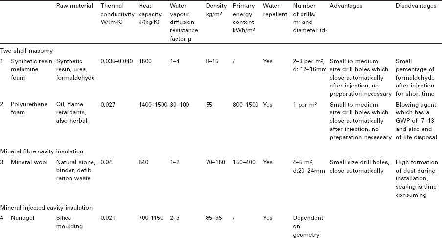
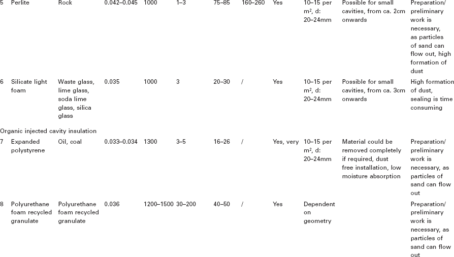
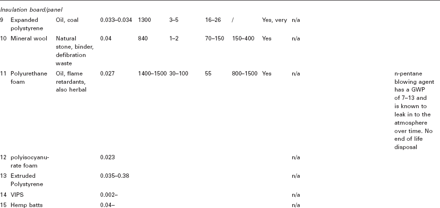
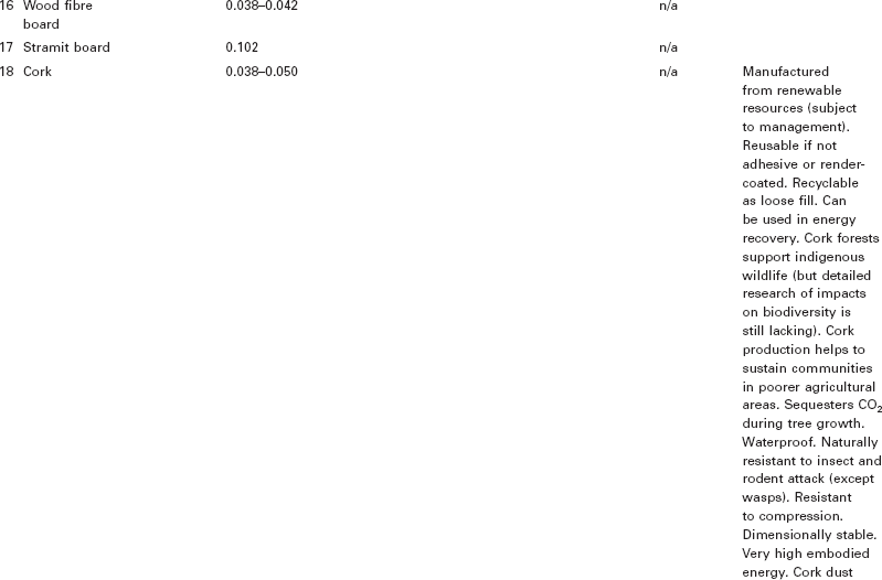
1Data and information are taken from (IPEG, 2011; Jansen, 2010; CIBSE, 2006; Green Spec, 2010)
Cavities present technical challenges when retrofitting as moisture penetration due to bridging and/or interstitial condensation can sometimes occur. In the case of minor defects in the construction process, or bad workmanship, the external wall layer may not be sufficient in terms of resistance to rainwater penetration – a situation that leads consequently to the danger of capillary moisturisation and humidification of the insulation. In this case it is essential to use a hydrophobic or water-repellent insulation material. This situation can equally apply to stabilised compressed earth block walls, where an unfilled air cavity has been left in place as part of the construction, or if the earth wall forms part of a composite cavity wall construction, e.g. with internal/external timber frame and cladding.
In the UK, cavity wall construction was introduced as a method to stop wind-driven rain from penetrating to the inside surfaces of masonry walls (Howell, 2008). The Energy Savings Trust started to financially support the injection of insulation material in cavities. This funding continues today in many parts of the UK. The current scheme, which is the third of its kind, is driven by the UK carbon emission target and has been in place since 2008. In this process the partially ventilated cavity air layer in between the outer and inner leaves that originally gave only limited thermal insulation is now filled with an insulating material (Table 3.1). The question that remains is if cavities were intentionally built as air voids, but subsequently filled at a later stage in the buildings life, how does this alter the dew point and hygroscopic characteristics of the wall?
The thermal resistance of the post-filled cavity wall is of course limited by the thermal conductivity of the blown loose fill insulation medium (e.g. ~ 0.04 W/m K for glass fibre) and the thickness of the air cavity (typically around 50 mm) and so any ambitious retrofit U-value targets are likely to require additional internal/external insulation.
The initial idea of the cavity is to stop water penetrating through the wall to the inside of the house. Since 1974, the Building Regulations have required new build houses to contain insulation material in the cavity (Building Regulation, part L), and in theory this should give an ideal way of insulating the building as long as it is correctly detailed. As a result a number of different insulation products have been developed that can be fixed on to the inner leaf of a cavity wall, leaving a small air gap to prevent rainwater from being directly wicked across the wall. For this reason the (often hydrophobic) insulation material allows the rainwater and any condensate build up to drain downwards, under the influence of gravity and the presence of vertical aligned fibres. However, most problems occur in cases where insulation was retrospectively added to create a fully filled cavity resulting in damp problems due to a non-water-repellent material being used such as mineral or glass fibre. What happens as a result is that moisture is transferred back to the inner leaf of the construction and houses become damp and mouldy on their inside, and consequently the buildings become structurally damaged and uninhabitable.
The problem of rainwater crossing the cavity wall insulation is well documented (BRE Building Guide). It is stated that:
‘there can be an increased risk of rain penetration if a cavity is fully filled with insulation, i.e. moisture is able to transfer from the outer to the inner leaves resulting in areas of dampness on internal finishes. Rainwater, under certain driving rain conditions, can penetrate the outer leaf of masonry leading to wetting of the cavity insulation, a reduced thermal performance and damage to internal finishes’.
It has also been revealed that ‘single-leaf brick walls always leak when exposed to wind-driven rain’ (Stirling, 2000). The leakage occurs at the vertical joints between adjacent bricks, because of the drying shrinkage in the mortar (Stirling, 2000). This can be a particular problem for clay brick or concrete block masonry walls, as the BRE studies have shown, since the hydraulic conductivity (i.e. pressure-driven moisture ingress) and sorptivity (i.e. capillary-driven moisture ingress) are typically very high for these materials, especially in the case of decorative facing bricks as used on the external leaf of the cavity wall. This problem can be overcome if the materials are treated with waterproofing agents, however these are typically high volatile organic compound (VOC) solvent-based surface treatments (e.g. silicone emulsions) that penetrate and fill the material’s pore network. High-quality engineering brick, polished stone or walls of considerable thickness do not suffer the same level of moisture penetration. In the case of insulated SRE walls, the insulation used is a solid fill of interlocking boards usually made from extruded polystyrene (XPS), polyisocyanurate (PI) or expanded polyurethane (PU) (see Table 3.1). All are suited/designed for solid wall applications where the use of cavities is not possible and the insulation has to resist compression (e.g. during compaction of the adjacent earth material) and be resistant to moisture ingress or damage. SRE is high density (typically > 95% Proctor compaction) and so has very low permeability and sorptivity (Walker and Stace, 1996; Hall and Djerbib, 2004). Particularly for cavity rammed earth walls, where the inner and external leaves are usually a minimum of 175 mm thick in a load-bearing wall, the mix design must also include a hydrophobic admixture. This has the effect of significantly reducing liquid transport and effectively rainproofing the wall material, but leaving the macropore network open such that vapour permeability is largely unaffected. For more details of hydrophobic admixtures refer to Chapter 10. Note that masonry cavity walls typically have an inner/outer leaf thickness of 102.5 mm for fired clay brick or 100 mm for concrete block.
Condensation will always form on the coldest surface in a wall construction, which is typically found at the window/wall connection or areas of thermal bridges. Cold spots resulting from geometric or construction-related thermal bridges reduce the localised moisture-holding capacity of the air resulting in water vapour condensing, a phenomenon commonly referred to as ‘interstitial condensation’.
A number of different materials used for cavity insulation are shown in Table 3.1. Commonly used in the UK are mineral wool fibre, bonded polystrene beads or insulation foams.
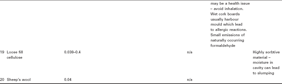
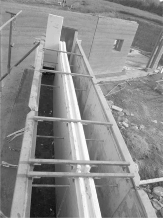
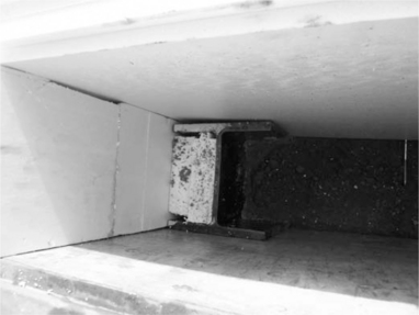
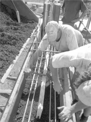
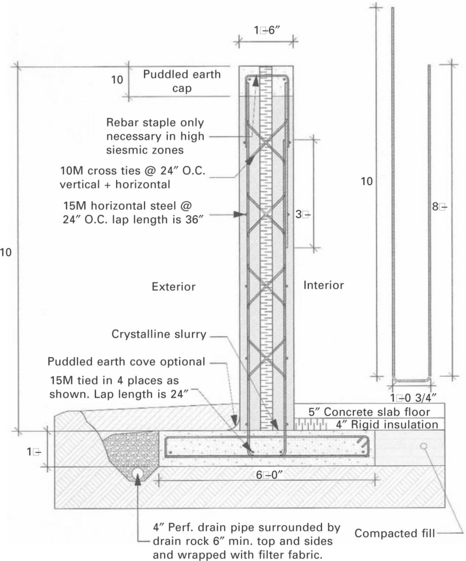
Figures 3.1, 3.2 and 3.3 show typical SRE solid cavity wall cross-sections during construction of Straightways farm, Devon, UK in 2007 by earth Structures (Europe) Ltd. Note that proprietary formwork systems have to be modified to allow the central insulation board to be mounted securely and allow compaction of the earth on either side. The two separate wall leaves are mechanically tied as for masonry walls but instead with specially designed stainless steel staples that become bonded with the compacted earth during compaction. This ties the two leaves together (both of which are supported by a common foundation) in order to prevent buckling, i.e. vertical bending moments. In cases of high wind loading or multi-storey walls, additional vertical restraint can be added, for example through the incorporation of stanchions. Where structural steel stanchions or similar framework members are included in the external wall fabric, continuity of the insulation can be achieved with careful detailing to avoid any risk of thermal bridging. Construction of stabilised insulated (cavity) earth walls in seismic regions (e.g. North West America) requires additional detailing and support in order to reduce ‘mass mobilisation’ and the likelihood of cavity tie failure/buckling. Figure 3.4 shows a stablised insulated rammed earth (SIREWALL) construction detail which addresses all of these concerns by incorporating a rigid cross-braced steel framework to tie the two leaves together, coupled with vertical restraint from the reinforced foundation slab and puddle earth cap.
3.1 SRE cavity wall with 175 mm inner/outer leaves and 50 mm interlocking extruded polystyrene insulation core used in conjunction with Stabilform™ formwork system. (© Earth Structures Europe Ltd 2007)
3.2 Insulation detail around a steel stanchion to avoid cold bridging across a solid external SRE wall. (© Earth Structures Europe Ltd, 2007)
3.3 Thermal bridging theory
In order to implement effective and competent design of the thermal insulation a major obstacle has to be overcome. Thermal bridges are the main source of thermal losses especially in new buildings. They can contribute as much as 50% of the total negative heat exchange (Schnieders, 2009). Therefore, thermal bridges have to be carefully investigated and checked when the architect/engineer is detailing the outer thermal envelope. Thermal bridges are defined as points along a building’s envelope where the surface temperatures and/or the heat flow rate changes. They occur most often at junctions or when there is a change in the material composition of a building element. Thermal bridges can cause not only significant heat losses but also undesired condensation and mould growth (Mao and Johannesson, 1997). Lowered temperatures on the internal surface of the building can lead to vapour condensation, which in turn creates a suitable environment for mould and fungal spores to develop, thus causing damage to the construction (Kornicki, 2011) and posing health risks to the occupants. Thermal bridging therefore gives rise to two and three-dimensional heat flow paths, which can be approximated accurately using numerical methods (the most common is iterative finite Element Analysis). Since numerical methods require a significant number of iterations, it is almost impossible to create and solve a model without being assisted by a computational tool (Tilmans and orshoven, 2009).
A common way to evaluate thermal bridges is by using numerical methods. Most dynamic simulation programmes are very simplified and assume one- dimensional (1D) heat flow through the thermal envelope (e.g. Energy +, TRNSYS, CODYBA 6.0) (Gao et al., 2008). The 2D or linear thermal bridges (Figure 3.5) can be analysed by bespoke thermal bridging tools such as Heat3, TB3D/FMD for heat flow at local positions or for analysis of temperature fields. KOBRU86 software (Physibel, 2011) allows 2D steady-state thermal bridge analysis; and offers in combination with the EUROKOBRA database a number of catalogues with more than 3000 thermal bridge details. Several research studies have shown that this approach provides a user-friendly way to analyse thermal bridges (Strachnan et al., 1995; Hopfe and Manolov, 2011; Ben-Nakhi, 2003).
3.5 Example of thermal bridging and temperature gradient due to lack of continuity in fabric insulation at the eaves.
An example of a 2D thermal bridge study on window performance, using THERM 5.2, is shown by Cappelletti et al. (2011). They particularly show the difference in a number of window–wall junctions for externally insulated walls and for walls with cavity insulation. The outcome shows the importance of correct frame positioning, and shows similar outputs are achievable for both the external insulated and cavity wall examples.
Another 2D calculation case study conducted by Theodosiou and Papdopoulous (2008) in Greece using TRNSYS, shows the impact of thermal bridges on the total energy demand in buildings by analysing four different wall configurations involving both external and cavity wall insulation. 3D or point thermal bridge studies appear in 3D corners or in the case of an insulated wall that is perforated by ‘an element with high thermal conductivity’ (Ben Larbi, 2005). In the context of a whole building simulation (1-year simulation with 1-h time step), a 3D calculation will place exceptionally high demands on computational power and time. An example of 3D thermal bridge studies can be found in Ben-Nakhi (2002), who developed a 3D gridding module that is integrated in the Building Performance Simulation BPS tool ESP-r for dynamic ‘whole building’ thermal bridging assessment. Results are tested and validated with VOLTRA from Physibel (Physibel, 2009). A more simplified model is proposed by Gao et al. (2008) who introduced a reduced heat transfer model in 3D that can be potentially implemented into standard BPS.
From a practical perspective it is appropriate to investigate the available software packages designed to calculate multidimensional heat flow in a building (Tilmans and Orshoven, 2009). An overview of some of the more commonly used software is shown in Table 3.2. One essential point is the conformance with the European Norm BN EN ISO 10211: 2007 ‘Thermal bridges in building constructions – Heat flows and surface temperatures – Detailed calculations’. The above standards set requirements and defined methods for accurate calculation of two- and three-dimensional heat flow. Tools that conform to this standard can be successfully used in the design and implementation of an accurate and standardised method for assessing the quality of the proposed thermal envelope (British Standards Institution, 2009).
Table 3.2
Numerical modelling simulation tools for assessing thermal bridging in building fabric
| Tool | Key words | Website |
| AnTherm | Thermal bridge 2D, 3D, steady-state heat transmission (conduction), ISO standard conformant | www.kornicki.com/ |
| Delphin | Heat, air and moisture transport, building envelope | http://bauklimatik-dresden.de |
| Flixo | 2D heat transfer, frame (U-value, thermal bridge | www.infomind.ch/bph/en/ |
| Trisco Physibel | Thermal bridge 2D, 3D, free form, rectangular forms for steady-state and transient | www.physibel.be/ |
| THERM | 2D heat transfer, building products, fenestration | http://windows.lbl.gov/software/therm/therm.html |
| WUFI | Hygrothermal modelling, combined heat and moisture transport | www.wufi-pro.com/ |
| Psi-Therm 2011 | Thermal bridge, DIN 4108 incl. Beiblatt2, EN ISO 10211:042008, EN ISO 6946 | www.psi-therm.de/ |
Note that only two-dimensional flow will be shown in the following. It is assumed that two-dimensional heat flow modelling is adequate to assess thermal bridging to an acceptable level of accuracy in most cases (Tilmans and Orshoven, 2009). Heat flow through thermal bridges cannot be adequately assessed using one-dimensional models as stated above. Two-dimensional models can however predict heat flow behaviour to an accurate extent. In two-dimensional modelling cut-off planes are defined to isolate the full extent of any thermal bridge present (i.e. glazing system-to-wall connection, balcony-to-wall, roof ridge junctions, etc.). The cut-off plane represents a cross-section of the element to a point where the heat flow becomes once again one-dimensional. By inputting appropriate boundary conditions a model can thus be used to determine the sum of all two- or three-dimensional heat flows.
3.3.1 Two-dimensional calculations
Several factors have to be addressed when calculating a two-dimensional flow and, in particular, 2D thermal bridges. A major requirement is that the model conforms to the geometrical requirements stated in BS EN ISO 10211:2007. Once an accurate model of the desired problematic area has been created, materials have to be assigned in accordance with the architect’s specifications. Thermal conductivity values of the material can be found in BN EN ISO 10456 (British Standards Institution, 2009). Where these are not listed, values that conform to CE testing procedures should be used in favour of manufacturers’ stated values, which are in many cases misleading. Finally, appropriate boundary conditions in terms of temperatures and surface resistance of the corresponding environments are to be assigned in accordance with EN ISO 120011-1 (Ben Larbi, 2005). Once the model has been implemented, calculation of the thermal coupling coefficient and linear thermal transmittance can be executed according to the specified requirements. It is therefore appropriate to define the components contributing to the total (two-dimensional) heat exchange between both environments (Ward and Sanders, 2007).
Thermal coupling coefficient (L2D) is defined as the heat flow rate per temperature difference between internal and external environments. According to EN ISO 10211:2007, 2D thermal coupling coefficients can be calculated as shown in Equation 3.2:
Linear thermal transmittance, known as the Psi value (Ψ), is the residual heat flow when the one-dimensional heat flow (all elements inc.) is subtracted from the total heat flow per unit temperature difference, i.e. the 2D thermal coupling coefficient (Ward and Sanders, 2007) as shown Equation 3.3:
Point thermal transmittance, known as the Chi value (χ), is the residual heat flow when the one-dimensional heat flow and the linear transmittance are subtracted from the three-dimensional coupling coefficient (Ward and Sanders, 2007).
3.3.2 Total heat flow
Total heat transfer through the building envelope can be defined by Equation 3.4.
The first term Ai · Ui represents the thermal transmittance through the area of the plane element. If only this term is considered, then the problem becomes one-dimensional. It is commonly the most significant source of heat loss within Equation 3.4 (Ward and Sanders, 2007) and occurs at plane elements including roofs, external walls, floors, and doors/windows (Kuhnenne, 2008). The second term lk · Ψ k represents the sum of all linear thermal bridges in the envelope, where Ψ is the linear thermal coefficient and l is the length of the thermal bridge. Ψ can be estimated by subtracting the thermal transmittance component A · U from the two-dimensional coupling coefficient defined previously as L2D (Ward and Sanders, 2007). This term is relevant to heat transfer that occurs at thermal bridges including eaves and corners, i.e. a geometric thermal bridge (Kuhnenne, 2008) as shown by Figure 3.5.
The third term χj represents the point thermal bridges within the structure. They occur as a result of the interaction of the linear thermal bridges or where the residual heat flow at either boundary is three dimensional. Usually, they can be omitted from the total heat transfer calculation because their contribution is insignificant. However, in certain situations, they have to be included for a more accurate solution, e.g. at penetrations where the point thermal bridges are either frequent or very large, such as poorly insulated structural frame elements including steel stanchions. Therefore calculating accurate U and Ψ will be of major interest when comparing the value of computational packages (Ward and Sanders, 2007) and is of significant importance in the design of low energy buildings.
3.3.3 Humidity and condensation
One of the main problems associated with thermal bridges aside from the thermal losses are the cold regions of minimum temperatures on the internal surfaces of the building. Lowered temperatures can lead to condensation, which is an undesirable effect in contemporary design. Condensation leads to mould growth and premature deterioration of the construction materials (Kuhnenne, 2008). It is therefore vital to numerically determine the temperatures on the internal surface of the model. Once the minimum temperature on the internal surface is known, the temperature factor fRsi can be estimated. The temperature factor must be a minimum value of 0.7 in order to avoid condensation and mould growth (Kuhnenne, 2008). The temperature factor fRsi can be defined by Equation 3.5.
θsi,min is the threshold internal surface temperature below which condensation can occur. Note that condensation depends upon the predefined internal relative humidity within the model (Kuhnenne, 2008).
3.4 Thermal bridging simulation tools
The Finite Element Method (FEM) is a calculation method for a structural element consisting of small elements, where the thermal quality of each element can be almost exactly defined. If a net is laid over the structural element, all junctions are defined. From this nodal grid the thermal properties of the whole element can be calculated. There are a number of well- established finite element computer programs for the calculation of two- or three-dimensional heat fluxes. A brief summary of a number of simulation software tools that can be used to predict thermal bridges in buildings is presented in Table 3.2.
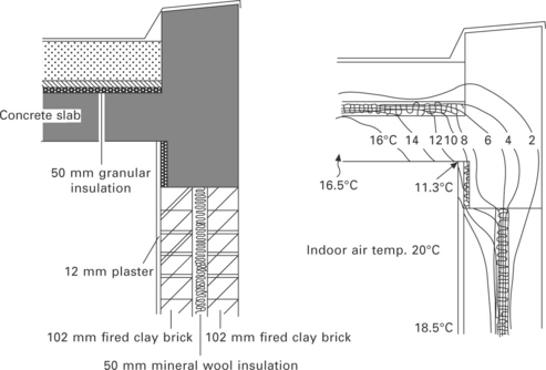
Figures 3.6 and 3.7 show the modelling of an external wall-to-ground floor joint from a PassivHaus project in Ebbw Vale, South Wales. This particular section is one of the most difficult parts to design in terms of achieving the minimum threshold U-value of equal or less than 0.15 W/m2 K that is required in the PassivHaus standard. The pictures show the simulation of this problematic junction of the PassivHaus with two different simulation programs, Flixo and THERM.
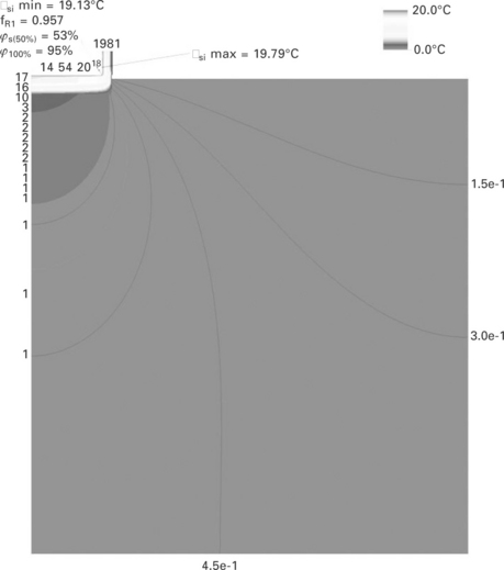
3.6 Temperature distribution of wall-to-ground junction, showing the min/max values, humidity and isotherms simulated with Flixo (Hopfe and Manolov, 2011).
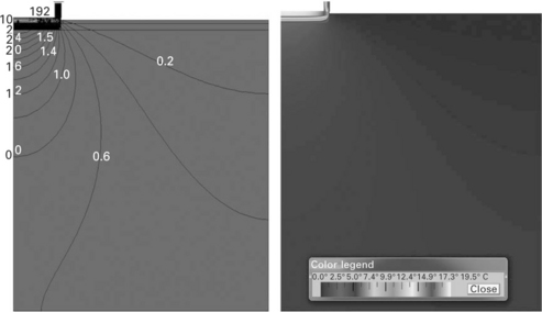
3.7 Temperature distribution of wall-to-ground junction, showing the isotherm lines and the heat flux diagram simulated with THERM (Hopfe and Manolov, 2011).
3.5 Acoustic reverberation
In addition to hygrothermal behaviour and indoor air quality, the acoustic isolation of a building is very important in terms of providing occupant comfort. This requires, for instance, research into the acoustic properties of building components and materials (e.g. solid or hollow bricks, sealing and insulating materials, sound absorptive qualities of materials). Typically this research is carried out using in-situ experimental design to isolate the acoustic properties of materials. Subsequently computational and experimental optimisation is possible including the complex interactions in buildings. Numerous different computational methods exist and can be compared to real-world measurements when determining the acoustic properties of an enclosed space. This analysis leads to the practical possibilities of sound reduction and acoustic harmonisation of buildings and their components – the sound absorption of suspended ceilings for instance, or floor coverings.
The importance of acoustic comfort is increasing as noise pollution and annoyance in buildings is growing. In many countries guidelines and legal requirements exist that help building towards sound isolation. In the UK, Building Regulation Part E (resistance to the passage of sound) sets such restrictions in terms of protection against sound from other parts of the ]building, protection within dwellings, reverberation in common internal parts or acoustic conditions in schools (Building Regulation Part E, 2010). Acoustic performance is significantly affected by the building structure, which can be seen for example in terms of the performances of heavyweight buildings (e.g. rammed earth, concrete or brick constructions) compared to lightweight structures (e.g. insulated timber frame). Even though new structures are being improved with respect to their structural performance, sustainability and adaptability, this is often achieved at the expense of sound isolation (Schönwald, 2008). More precisely, if a building is designed to deliver good thermal performance that does not automatically confer the preferred acoustic qualities. Particularly when looking at lightweight structures, certain types of insulation can actually harm acoustic behaviour and have an increasing deleterious effect on noise reverberation and the sound absorption of the structure.
The thermal and acoustic properties of materials may exhibit contradictory behaviour. Building materials and wall constructions that provide good acoustic absorption usually have a low thermal inertia and vice versa, which will be shown in the following. It is therefore important to understand the physics involved in acoustic comfort, to know about the relevance of thermal inertia and the absorption coefficient, and to find the right balance between these factors in order to simultaneously deliver acoustic and thermal comfort in buildings.
3.5.1 Reverberation time
The most commonly used simplified model to calculate reverberation time, is that of the Wallace Sabine approximation. This assumes the speed of sound to be constant at 343.3 m/s, and at 20 °C the term 2.76/t0.5 = 0.161 s/m. If sound is reflected off a surface several times, the reverberation time is the time required for reflections to decay by 60 dB. The reverberation time is frequently stated as a single value, however, it can be assessed based on three versions of the diffuse-field theory (Citherlet and Macdonald, 2003). Typically, the reverberation time differs depending on the frequency band being measured. The frequency-dependent reverberation time can therefore be expressed by Equation 3.5.
The Wallace Sabine equation states that tr is directly proportional to the volume, V, of the room, but inversely proportional to the room’s effective surface area, Aftot. The effective surface area is the sum of the individual products of an area covered by a particular material multiplied by the material’s absorption coefficient (α) as shown in Equation 3.7.
The reverberation time in a room is thus affected by the size and shape of the enclosure and the materials used in the construction of the room. Furthermore, every object that is in the room will impact on the reverberation time, including occupants and furniture. The theoretical model, from which these equations are derived, requires the decaying sound field to be perfectly diffuse. According to Citherlet and Macdonald (2003):
‘This idealised condition is sufficiently fulfilled in practice when: (a) no room dimension is markedly different from the others; (b) room dimensions are large compared to the wavelength, which is the case in most building acoustics; (c) absorption is distributed almost uniformly over the enclosure boundaries.’
3.5.2 Acoustic absorption
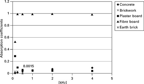
Sound is absorbed because of its reflections at the enclosure boundaries during the propagation. At each successive reflection, the enclosure boundaries and all objects within the enclosure absorb a fraction of the sound energy. The fraction of absorbed sound is dependent upon the frequency of the emitted sound and the capacity of the reflecting material to absorb this frequency. For instance, concrete is a rather poor sound absorber compared to fibreboard, as shown in Fig. 3.8. The total absorption is the product of the absorption coefficient of all materials multiplied by the area. In practice this calculation has to be conducted at a number of different frequencies due to the fact that the absorption coefficient is not constant across frequencies. The absorption coefficient of a material is a number between 0 and 1 that indicates the proportion of sound absorbed by the surface compared to the proportion which is reflected back into the room. For example, in the situation of an open window without any sound reflections whereby sound would pass straight outside, this would be a perfect absorber and have an absorption coefficient of 1. The opposite of this might be a thick concrete ceiling, which is smooth and painted, and is from an acoustic point of view the equivalent of a mirror and has an absorption coefficient close to 0. The absorption coefficient varies with the frequency and so the reverberation time is a function of frequency. Some contractors have experimented by manipulating the surface texture of rammed earth walls, by adjusting the soil particle grading, in an attempt to alter the acoustic absorption coefficient SIREWALL (2011). This is an interesting avenue for further research as no detailed experimental data are currently available and yet could have significant potential for application in performing arts buildings, recording studios and other similar building typologies.
3.5.3 Correlation with thermal inertia
Thermal inertia describes the combined effect of heat storage capacity within the wall and the thermal resistance to movement of heat through the wall. The following equation refers solely to thermal mass and does not take into account the thermal resistance of the wall, however it is an often-used formula to describe the thermal inertia of a material. Table 3.2 shows the impact of different materials and frequencies of the absorption coefficient. The thermal inertia, I, of a material is defined as the square root of the product of the material’s thermal conductivity, density and specific heat capacity. It therefore quantifies the capacity of a material to store surrounding heat and to release it when surrounding temperature drops, as defined in Equation 3.8:
Note also that this is a simplified equation and does not, for example, describe solar absorption coefficients as either part of the boundary equation or the limits of 24-hour cycling.
In contrast to its acoustic performance, concrete has a higher capacity to store heat (thermal inertia) than fibreboard, because of its higher density and thermal conductivity. This higher thermal inertia generally increases absorption of solar gains, and reduction in internal heat gains may improve occupants’ thermal comfort, especially for spaces with large glazed areas and no cooling plant. To provide a well-designed building, a balance must be found between acoustic absorption and thermal inertia. Earth brick walls make a significant contribution towards achieving adequate acoustic performance (Morton et al., 2005). The performance of earth brick walls is very good in terms of thermal and acoustic performance and could be enhanced by avoiding flanking transmission. It is also good practice to repair initial shrinkage cracks, which may affect acoustic performance. The reason why soil functions particularly well in terms of thermal inertia is due to the combination of relatively high volumetric heat capacity and thermal conductivity. With its low thermal diffusivity, earth walls possess the ability to dampen and delay internal thermal variations in response to external inflows.
Table 3.3
Different materials and their thermal inertia and absorption coefficient in relation to different frequencies
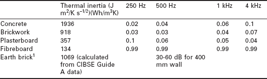
1Adobe brick 380 Wh/m3K and Rammed Earth 590 Wh/m3K (Houben and Guillard, 2003)
3.5.4 Acoustics and building performance simulation
It is important to realise that with regard to building acoustics it is all about getting the shell of the building right in the first instance. It is almost impossible to retrofit proper acoustic performance (May, 2009). Elsewhere as in Europe traditionally, buildings typically consisted of heavy monolithic constructions such as masonry walls with earthen or stone floors. With the advent of concrete blocks and monolithic construction, the first models for the prediction of sound isolation were based on a simple mass law where only transmission through the partition between two rooms was considered (Schoenwald, 2008). A large number of building simulation tools that provide computational models to predict sound isolation and acoustics in buildings are now widely available. The weighted Sound Reduction Index (Rw) of a solid wall is strongly dependent on the dry density of the material. SRE is a monolithic wall fabric where the dry density (ρd) is typically high, ranging between 1900 and 2200 kg/m3. According to the ‘acoustic mass rule’ for solid walls, as defined by BS 8233 (British Standards Institution, 1999), Rw can be calculated using:
According to the Building Regulations (2000) Approved Document E: ‘Resistance to the passage of sound’, the laboratory values for new internal walls within houses, flats and rooms for residential purposes must have a minimum Rw of 40 dB. A typical 300 mm thick solid SRE wall (without insulation), would have a weighted Sound Reduction Index (Rw) of 58.3 dB, assuming dry density to be 2100 kg/m3. A brief summary of a number of the simulation software tools that could be used to better predict the acoustic performance of buildings are listed in Table 3.4.
Table 3.4
Overview of simulation tools available for assessing the acoustic performance of buildings
| Tool | Key words | Website |
| ACOUSALLE | acoustics, codes and standards | http://lesowww.epfl.ch/anglais/Leso_a_frame_sof.html |
| Acoustics programme | HVAC acoustics, sound level prediction, noise level | www.trane.com/commercial/software |
| CYPE-Building Services1 | Analysis of acoustic behaviour, building services, energy simulation, sizing, HVAC, electricity, solar | http://instalaciones.cype.es/ |
| ECOTECT | Geometric and statistical acoustic analysis, environmental design and analysis, conceptual design, validation, solar control, overshadowing, thermal design and analysis, heating and cooling loads, prevailing winds, natural and artificial lighting, life cycle assessment, life cycle costing | www.squ1.com |
| ESP-r | Integrated energy modelling tool for the simulation of the thermal, visual and acoustic performance of buildings | www.esru.strath.ac.uk/Programs/ESp-r.htm |
| DONKEY | Self-generated noise, room sound pressure level, duct sizing, static regain, balanced pressure drop, duct acoustics | www.ozemail.com.au/~acadsbsg |
3.6 Sources of further information
The following section provides brief details and links to sources of further information that will enable readers to tackle specific and advanced problems relating to thermal bridging and heat transfer in insulated and non-insulated building fabric. Numerical simulation/methods and tools can be generally divided into the following four categories:
1. FEM (finite-element method) such as Ansys, LSDyna, Nastran, Abaqus
2. Multibody system such as ADAMS, Dymola, Partial Flow Code PFC
3. CAS (computer Algebra system) such as Maple, Matlab/Simulink
Ansys/CFX
Ansys/CFX is a fluid dynamics program with integrated solver that captures any type of phenomena related to fluid flow.
More information on www.ansys.com/.
Tutorial on http://seam.ustb.edu.cn/UploadFile/20080512040742250.pdf.
Ansys Fluent
The software package Fluent is a commercial CFD package with ancillary software called Gambit that is used to create mesh representations of the object that is being studied (typically purchased with Fluent).
More information on www.ansys.com/andwww.ansys.com/Products/Simulation+Technology/Fluid+Dynamics/ANSYS+FLUENT/Features.
Tutorial on www1.ansys.com/customer/content/documentation/121/fluent/flwbtg.pdf.
PHOENICS
The CFD package Phoenics from CHAM has a range of applications models that can be implemented including architectural airflows, safety, fire spread, environmental pollutant dispersal, simultaneous stress/flow analysis, amongst others.
More information on www.cham.co.uk/.
Fire Dynamics Simulator (FDS)
The free software FDS was developed by the National Institute of Standards and Technology (NIST) of the United States Department of Commerce, in cooperation with VTT Technical Research Centre of Finland. It is a CFD model of fire-driven fluid flow. The software solves numerically a large simulation form of the Navier–Stokes equations appropriate for low-speed, thermally driven flow, with an emphasis on fire smoke and heat transport.
More information on http://fire.nist.gov/fds/.
Others
More information with respect to freeware preprocessing (meshing), and solver programs available on http://wiki.ubuntuusers.de/CFD_-_Str%C3%B6mungssimulation.
3.7 References
Ben Larbi, A. Statistical modelling of heat transfer for thermal bridges of buildings. Energy and Buildings. 2005; 37(9):945–951.
Ben-Nakhi, A.E. Development of an integrated dynamic thermal bridging assessment environment. Energy and Buildings. 2003; 35(4):375–382.
British Standards Institution. BS 8233 Sound insulation and noise reduction for buildings. In: Code of practice. London: BSI; 1999.
British Standards Institution. BS EN ISO 10211:2007. In: Thermal bridges in building constructions – Heat flows and surface temperatures – Detailed Calculations. London: BSI; 2009.
Building Regulation part E, 2010. Resistance to the passage of sound, 2003 edition incorporating 2004 and 2010 amendments, HM Government, available from www.planningportal.gov.uk/uploads/br/BR_PDF_ADE_2003.pdf
Building Regulation part L, Part L. Conservation of fuel and power, HM Government, 2010. available from www.planningportal.gov.uk/uploads/br/BR_pDF_ADL1B_2010.pdf
Cappelletti, F., Gasparella, A., Romagnono, P., Baggio, P. Analysis of the influence of installation thermal bridges on windows performance: The case of clay block walls. Energy and Buildings. 2011; 43(6):1435–1442.
CIBSE A. Guide A: Environmental design. In: Category: Heating, Air Conditioning and Refrigeration. London: CIBSE; 2006.
Citherlet, S., Macdonald, I. Integrated assessment of thermal performance and room acoustics. Energy and Buildings. 2003; 35(3):249–255.
Department of Energy, tools directory, http://apps1.eere.energy.gov/buildings/tools_directory/, last accessed March 2011
Department of Trade and Industry. Energy consumption in the United Kingdom. London: Energy Publications, Department of Trade and Industry; 2001.
Gao, Y., Roux, J.J., Zhao, L.H., Jiang, Y. Dynamical building simulation: A low order model for thermal bridges losses. Energy and Buildings. 2008; 40(12):2236–2243.
GreenSpec, Introduction to Passivhaus, [online], 2010. Available at www.greenspec.co.uk/passivhaus-introduction.php [(accessed 11 February 2011)].
Hall, M., Djerbib, Y. Moisture ingress in rammed earth: Part 3 - The sorptivity and the surface inflow velocity. Construction and Building Materials. 2004; 20(6):384–395.
Hens, H., Janssens, A., Depraetere, W., Carmeliet, J., Lecompte, J. Brick cavity walls: A performance analysis based on measurements and simulations. Journal of Building Physics. 2007; 31:95.
Hipworth, M. Thermostat settings in English houses: No evidence of change between 1984 and 2007. Building and Environment. 2011; 46(3):635–642.
Hopfe, C.J., Manolov, S. Overview of simulation tools for 2D thermal bridge calculation, internal report. Cardiff: Cardiff University; 2011.
Houben, H., Guillard, H. Earth Construction: a comprehensive guide. London: ITG Publishing; 2003.
Howell, J. The rising damp myth. Woodbridge: Nosecone Publications; 2008.
Institut für preisoptimierte energetische Gebäudemodernisierung GmbH, 2011. www.ipeg-institut.de/index.php?article_id=1 [(last accessed June 2011)].
International Organisation for Standardisation (ISO). ISO 9613/1 Acoustics – Attenuation of sound during propagation outdoors – Part 1 – Calculation of the absorption by the atmosphere. London: ISO; 1993.
Jansen, H., Übersicht verschiedener Kerndämmstoffe zur Hohlwandsanierung und die wichtigsten Eigenschaften im Vergleich Available at, 2010. www.daemmen-sanieren.de [(last assessed 2010)].
Kornicki, T. AnTherm. 6.2. Computer program. Vienna, Austria: T. Kornicki Ltd.; 2011.
Krus, M., Sedlbauer, K., Künzel, H. ‘Innendämmung aus bauphysikalischer sicht’, presentation at the event Innerdämmung – eine Bauphysikalische Herausforderung, 21 April. Germany: Münster; 2005.
Kuhnhenne, M. Thermal bridges – Sandwich panel constructions. In: Feldmann M., ed. Thermal bridge junctions. Edinburgh: European Quality Assurance Association for Panels and Profiles; 2008:1–33.
Langdon, D., Study on hard to fill cavity walls in domestic dwellings in Great Britain. Undertaken by Inbuilt Ltd & Davis Langdon, 2010. [DECC ref: CESA EE0211, Inbuilt ref, 2579-1-1].
Mao, G., Johannesson, G. Dynamic calculation of thermal bridges. Energy and Buildings. 1997; 26(3):233–240.
May, N., Why build better? Available at, 2009. www.nbtconsult.co.uk/resources.html
Morton, T., Stevension, F., Taylor, B., Charlton Smith, N. Low cost earth brick construction. Available at www.arc-architects.com/downloads/Low-Cost-Earth-Masonry-Monitoring-Evaluation-Report-2005.pdf, 2005.
Physibel, TRISCO and KOBRU86, User Manual, 2002. [last updated on 8 February 2011].
Physibel, Voltra and SECTRA, User manual last updated on 08.02.2011, 2002. available at www.physibel.be/v0n2vo.htm
Schnieders, J. A quantitative investigation of some passive and active space conditioning techniques for highly energy efficient dwellings in the South West European region, 2nd corrected edition. Darmstadt: Passivhaus Institute; 2009.
Schoenwald, S., Flanking sound transmission through lightweight framed double leaf walls – Prediction using statistical energy analysis, PhD thesis, TV Eindhoven, the Netherlands. 2008.
SIREWALL - Stabilized Insulated Rammed Earth; available at: http://www.sirewall.com/portfolio/residential-projects/lakeside-grand-piano/(Accessed 23 September 2011)
Stirling, C. Good Building Guide (GBG) 44: 2000, Part 2: Insulating masonry cavity walls: principal risks and guidance. Watford: IHS BRE Press; 2000.
Strachnan, P., Ben-Nakhi, A.E., Sanders, C. Thermal bridge assessment. Proceedings of Building Simulation. 1995; 95:563–570.
Theodosiou, T.G., Papadopoulos, A.M. The impact of thermal bridges on the energy demand of buildings with double brick wall constructions. Energy and Buildings. 2008; 40(11):2083–2089.
Tilmans, A., Orshoven, D.V. Software tools and thermal bridge atlases (4 March), Belgian Building Research Institute (webinar). Available at: www.bbri.be/homepage/index.cfm?cat=publications, 2009. [(Accessed 25 November 2010)].
Walker, P., Stace, T. Properties of some cement stabilised compressed earth blocks and mortars. Materials and Structures. 1996; 30:545–551.
Ward, T., Sanders, C. BR497 – Conventions for calculating linear thermal transmittance and temperature factors – part of the research programme of the Sustainable Buildings Division of the Department for Communities and Local Government. Watford: HIS BRE Press; 2007.
3.8 Appendix: nomenclature
I thermal inertia, also known as thermal effusivity, β (W s1/2/m2 K)
T absolute temperature, e.g. of air (K)
Aftot total equivalent area of an enclosure for frequency f (m2), that includes absorption due to boundaries, furniture, occupants and air.
U Thermal transmittance (W/m2 K)
θsi,min Threshold internal surface temperature (°C)