
Soil stabilisation and earth construction: materials, properties and techniques
Abstract:
This chapter describes the advantages and disadvantages of soil stabilisation, within the context of both soil mechanics and construction materials, and with specific reference to stabilised compressed earth construction, i.e. rammed earth and stabilised compressed earth blocks. Each of the key types of inorganic binder stabilisers are discussed at length including specific sections on high-calcium and naturally hydraulic hydrated limes, Portland cement and composite cements including pozzolanic materials and bituminous emulsions. In addition, stabilisation technologies such as synthetic and natural binders, including polymers, resins and adhesives, as well as fibre reinforcement are included. The chapter gives advice on stabiliser type selection and dosage rates with regard to compatibility with key soil characteristics, complemented by details of a selection tool and decision chart.
9.1 Introduction
The three forms of soil stabilisation collectively refer to various techniques of modification to enhance the physical and/or mechanical properties of a soil for a specific application. This can include altering the texture and plasticity of the soil by, for example, adding or subtracting sand, clay, etc. It can also include compacting the soil to increase its resistance to loading. Or it can include the addition of inorganic binders (e.g. cement) to either enhance the strength and durability, or to make an otherwise unsuitable soil useable. This chapter explains the various stabilisation techniques, how they work and how to select the right one depending on soil type.
Soil stabilisation can be defined as the controlled modification of soil texture, structure and/or physico-mechanical properties. Not only is it extremely rare for a natural soil in the ‘as raised’ condition to be perfectly suitable for earth construction materials without any soil grading modification, but also most earth building techniques involve some form of compaction to form a strong, stable material. The approaches to stabilisation can be broadly classified as physical, mechanical or binding (Burroughs, 2001). Therefore, practically all earth construction materials are stabilised in some form, however the term is commonly applied only to the application of inorganic binder additives. Physical stabilisation is the modification of, for example, soil particle size distribution and plasticity by the addition/subtraction of different soil fractions in order to modify its physical properties. Mechanical stabilisation is the modification of soil porosity and inter-particle friction/ interlock, for example by compaction or other means. An inorganic binder is an additive that improves the strength, durability or other properties of the earth walls. Since mechanical and physical stabilisation techniques are already implicit in modern earth construction techniques (e.g. rammed earth, compressed earth blocks) as part of their criteria for material selection and preparation, the focus of this chapter will be primarily on inorganic binder stabilisation. As with all bound aggregates (e.g. concrete) water content can strongly affect the physico-mechanical properties of stabilised soils, and so they have different properties when saturated compared to dry. It is well known that soil strength and bearing capacity is much higher in the dry state, compared with the saturated state, due to the higher plasticity of saturated soil. Obviously the most common state that exists is partial saturation, as discussed in Chapter 8, and so the exact amount of water content can vary widely as a result of ambient weather conditions or ground water level.
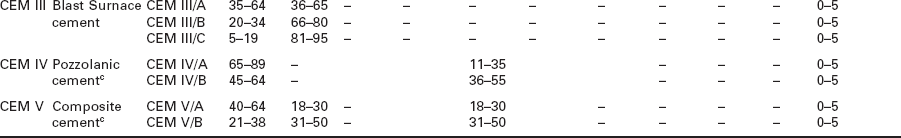
Many modern rammed earth construction companies routinely stabilise their soil with inorganic binders to ensure consistent quality in terms of mechanical performance, durability, resistance to moisture ingress and thermo-mechanical loading, i.e. thermal expansion-contraction. The most common forms of soil stabilisation are Portland cement, non-hydraulic lime, hydrophobic admixtures (see Chapter 10) and sometimes bituminous emulsion. One general approach to soil stabilisation is proposed by the Australian Earth Building Handbook HB195 (Walker and Standards Australia, 2002) that non-hydraulic lime should be used to stabilise cohesive soils, and that hydraulic (e.g. Portland cement) and/or bituminous stabilisers should be used for granular soils. in line with this, the selection criteria for these stabilisation techniques can be summarised in the graph in Fig. 9.1 using the plasticity index and the relative amount of cohesive material (%wt soil mass below 80 m particle diameter) as the key parameters.
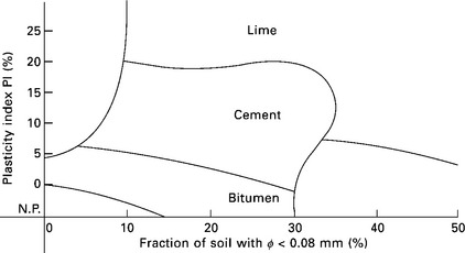
9.1 Selection criteria for common stabilisers with reference to soil characteristics (Houben and Guillaud, 1996).
However, there are several other options (in addition to lime and cement) for soil stabilisation including fibre reinforcement and polymers, for example. These will be discussed in the following sub-sections in terms of their composition, physico-mechanical properties and their adhesion/binding mechanisms. Other stabilisers include chemical admixtures that offer specific functional properties such as set acceleration/retardation of hydraulic binders, plasticisers and hydrophobic admixtures as discussed in detail in Chapter 10.
9.1.1 Advantages and disadvantages of stabilisation
In soil stabilisation there is no inorganic binder that can be applied indiscriminately, as a means of stabilisation, to ensure good results (Houben and Guillaud, 1996). Stabilised earth walls, however, may be built more thinly and there may be no need for the application of expensive surface treatments to improve durability and water tightness. In terms of durability, cement-stabilised materials such as rammed earth rarely have problems meeting the requirements of even the most severe tests (Walker and Standards Australia, 2002). A ‘modern’ building often results from the use of stabilised soils, which can be distinguished from ‘traditional’ earth materials, and can have higher status in certain regions such as developing countries (Keable, 1996). The decision to stabilise the soil mix should only be made after consideration of the following advantages and disadvantages:
Advantages
• Speeds up the building process as the required wall thickness is generally much less and so less material and labour is required
• Significantly improves durability and strength, particularly where the locally available soil is poor
• May reduce or eliminate the need for expensive surface treatment or rendering.
Disadvantages
• Raw material costs are increased – soil is free/low cost and cement is comparatively expensive
• The stabilisation materials needed may not be readily available in some developing countries or may be expensive to transport
• The processes of mixing and building can become more complicated depending upon the type of stabiliser that is chosen. This can increase the chance of problems occurring thus affecting time/budget
• Potential environmental impact – e.g. the use of cement and lime can increase the embodied energy (and associated CO2 emissions) of the wall materials
• Health and safety – cement and lime are both hazardous materials that can cause burns to the skin and eyes, some other chemical additives contain volatile organic compounds (VOCs).
Many guidelines are empirically derived and so are subject to change as the availability of experimental data and experience from industry practice constantly expands. A detailed study was conducted by Burroughs (2001) to produce an extensive database supported by statistical analysis to correlate the relationships between soil classification (Atterberg limits, particle grading and moisture content) and the ‘optimum’ stabilisation approach for lime and Portland cement using mechanical behaviour as the main assessment criterion. This has led to a more detailed selection framework and is discussed in Section 9.8.
9.2 Lime stabilisation
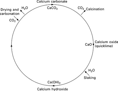
Lime is the common name given to the oxides and hydroxides of calcium and magnesium. High calcium limes are commercially produced through calcination of carbonate rock minerals (e.g. calcium carbonate; CaCO3) in the form of crushed chalk or limestone. Limes can also be produced commercially as dolomitic lime (Ca(OH)2 + Mg(OH)2) consisting of calcium and magnesium oxides that are then, for example, pressure hydrated. Calcination of high calcium carbonate rock minerals occurs at ~900°C and atmospheric pressure yielding the highly reactive calcium oxide or ‘quicklime’ (CaO), which can then be hydrated to the hydroxide form Ca(OH)2. This is achieved either using steam to produce a dry hydrate, or by slaking in water to produce a wet putty. This calcination–hydration–carbonation cycle is commonly known as the ‘lime cycle’ and is illustrated in Fig. 9.2.
Hydrated limes are commonly used for soil stabilisation in temporary road surfaces and for road sub-bases, especially where the sub-soil has a high percentage of cohesive fine aggregate and/or clay. This technique was first used by the Romans and other early civilisations for road construction and latterly was pioneered by civil engineers in the USA during the 1920s. Since this time it is approximated that millions of square metres of limestabilised roads have been constructed throughout the USA including large scale examples such as the ground infrastructure at Dallas Forth Worth Airport, which covers some 70 km2 (Houben and Guillaud, 1996).
Naturally hydraulic limes (NHLs) are those that are formed by the calcination of clay-bearing limestone or chalk parent rock. This has the effect of creating small quantities of dicalcium silicate (2CaO.SiO2), which exothermically hydrates to form calcium silicate hydrate (3CaO.2SiO2.3H2O), in addition to natural carbonation of the calcium hydroxide. For this reason NHLs are classed as ‘partially hydraulic’ and can be used as a higher strength, faster setting substitute for dry hydrate or lime putty. Roman cement was used historically to construct such buildings as the famous Pantheon in Rome. It consisted of hydrated lime mixed with very fine, reactive powder rich in amorphous silica. It was originally sourced as volcanic ash from the town of Pozzuoli in Italy, from which the present day term for these materials ‘pozzolan’ originates, but was also sourced in the form of fired clay brick dust and wood ash. There are several classifications of naturally hydraulic limes that are commercially available, as shown by Table 9.1. The names of each class are derived from the mechanical strength of the cured material, in which there is some flexibility due to the natural variation in composition of the clay-bearing limestone rocks from which it is manufactured.
Table 9.1
Classifications and properties of naturally hydraulic limes and allied materials
| Lime binder type | Mean compressive strength range at 28 days (N/mm2) | Initial setting time in water |
| Hydrated lime | 0.3–1.3 | N/A |
| Feebly hydraulic NHL 2.0 | 1.3–2.0 | 15–20 days |
| Moderately hydraulic NHL 3.5 | 2.0–5.0 | 6–8 days |
| Eminently hydraulic NHL 5.0 | 5.0–10.0 | 2–4 days |
| Roman cement | ≥ 10.0 | 15 mins–1 day |
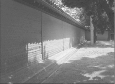
The Horyuji temple site is protected by the United Nations (UNESCO) and was Japan’s first World Cultural Heritage site. The extensive, lime-stabilised rammed earth wall that surrounds Horyuji Temple in Japan, as shown in Fig. 9.3, is thought to have been built between the dates 607 to 750 AD according to a local historian (Henman, 2002, pers. comm.) and is testament to the longevity of the material. Another example is the Taikoubei structure shown in Fig. 9.4, which is a lime-stabilised rammed earth wall connected to the main southern gate of the Sanjyusangen-Do Temple in Kyoto, Japan. It is thought to have been built in around 1610 by order of Toyotomi Hideyoshi. The Oonerihei wall structure was originally constructed somewhere between 1392 and 1466 AD for the Nishinomiya Shrine, in Hyogo-ken, Japan. In 1995, 24 of the 62 wall sections were damaged in the Kobe earthquake and were only repaired around ten years later. The wall panels are approximately 2.5 m tall, 4 m wide and 1.2 m thick, as shown in Fig. 9.5, and cover the entire perimeter of the shrine with a total combined length of approximately 247 metres. The soil that was available on-site is thought to have been mixed in equal amounts with a new soil, of low clay content, that was imported from elsewhere in order to improve the overall soil grading (Henman, 2002, pers. comm.). The soil mix was then stabilised with hydrated lime and ‘nigari’; a magnesium chloride-rich mineral deposit formed during the process of salt extraction from sea water. Apparently, the use of nigari was often recorded in ancient Japanese earth building although its use has now decreased. Today, magnesium-and calcium chloride-rich products are often used in the maintenance of earthen roads as a dust suppressant and so we may hypothesise that the use of nigari may have been for the same reasons.
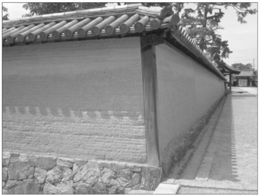
9.3 The lime-stabilised rammed earth perimeter wall that surrounds Horyuji temple, Japan. photo: courtesy Darel Henman © 2002
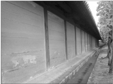
9.4 Taikoubei rammed earth wall – note the raised stone plinth, drainage channel and large eaves overhang on the roof. photo: courtesy Darel Henman © 2002
9.5 Oonerihei, Japan – note the degree of weathering and surface erosion on some of the wall sections is only minor for a wall that is over 500 years old. photo: courtesy Darel Henman © 2002
Chemical reactions involving clay and lime can form cementitious reaction products in the form of calcium silicate aluminate hydrate minerals that can significantly contribute to the strength of lime- and/or Portland cement-stabilised earth (Akpokodje, 1985; Bell, 1996). The reaction(s) takes place between calcium hydroxide (Ca(OH)2), free water and the silica and/or alumina minerals that comprise the clay particles. The Ca(OH)2 is highly alkaline (pH ~ 12.5) and has the effect of dispersing the clay particles into solution, which aids the reaction (Bell, 1996). The reaction is slow but exothermic and so the rate can be increased with temperature. The Ca(OH)2 is the main compound in high-calcium hydrated lime and is also a significant by-product during the curing of Portland cement. This reaction with the clay minerals is a form of the pozzolanic reaction referred to above, and is discussed in more detail in Section 9.4 below. Studies conducted by Reddy and Lokras (1998) have shown that for compressed earth blocks stabilised with both lime and the pozzolan ‘pulverised fuel ash’ (PFA), steam curing at ~ 80°C can produce high strength blocks with a compressive strength > 10 N/mm2 that are ready for use in construction after only 3 days. The elevated temperature and availability of moisture accelerates the curing by pozzolanic reaction(s), whilst the alkalinity of the lime disperses the clay during mixing, aiding uniform distribution of the binder.
9.3 Cement and pozzolans
Portland cement was patented in England in 1824 by Joseph Aspdin, and was so called because it resembled the high-quality grey limestone from the Island of Portland (UK) that, for example, was used to construct Buckingham Palace and other high-profile buildings. Portland cement is a hydraulic binder which is defined as ‘a finely ground inorganic material which, when mixed with water, forms a paste which sets and hardens by means of hydration reactions and processes and which, after hardening, retains its strength and stability even under water’ (BSi, 2000). The raw ingredients are calcium carbonate-bearing rock (e.g. chalk, limestone), clays and iron ore (haematite). These are pulverised to a fine meal before staged heating in a rotating kiln starting at temperatures of ~ 700°C increasing up to ~ 1400°C. The cooled product is known as clinker, which contains four main reactive compounds, as shown in Table 9.2. Note that the C3A compound is highly reactive and so a small quantity of gypsum (CaSO4.2H2O) is added in order to avoid flash setting, usually ≤ 5%wt.
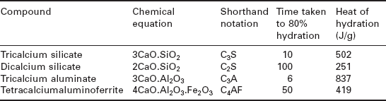
The relative amount of each compound in the clinker depends upon the proportions of raw ingredients and also the duration of certain firing temperatures within the cement kiln. The clinker composition therefore determines the properties of the cement, e.g. higher C3S content can increase setting speed and rate of strength gain, low C3A content can yield sulphate-resistant cement, higher C2S can yield lower heat of hydration cement, etc.
It is possible to estimate the relative proportion of each compound that could be formed from a known quantity of the principal oxides contained within each raw ingredient. Since the raw ingredients are mainly limestone, clays and iron ore the principal oxides will be CaO, SiO2, Al2O3, Fe2O3, plus several other minor quantity oxides. The %wt of each oxide can be entered into the empirically derived Bogue equation, as shown below.
One of the key assumptions is that all of the SiO2 is consumed in the formation of C2S, which is reasonable since this is formed at lower temperatures in the kiln. Any excess CaO then combines with C2S at higher temperatures to form C3S. The Bogue equation is therefore useful for predicting the total heat of hydration of a given clinker or estimating the rate of strength gain, resistance to chemical attack (e.g. sulphate) etc. Hardened cement has high Young’s Modulus (Modulus of Elasticity) and compressive strength but is typically hard and brittle. Obviously it can impart these properties to granular materials when used as a binder. The properties originate in the microstructure of the hardened cement paste, mainly due to the formation of the reaction product CSH, which arises from hydration of the di-and tri-calcium silicate phases as follows:
Of particular interest, at this stage, is the pozzolanic reaction, which follows the basic form:
This is the basis of Roman cement, discussed in Section 9.3, where calcium hydroxide (CH) combines with silica in the presence of water to produce CSH. Since CH is a by-product of the calcium silicate reactions (see above), additional silica, in the form of a ‘pozzolan’, can be added to the cement prior to hydration. A good candidate for a pozzolan should be a finely divided powder that is (i) high in silica content (preferably amorphous) and, (ii) has a high specific surface area. Adding pozzolans to cement can result in significantly increasing the relative proportion of CSH in the hardened cement paste, thus increasing strength and stiffness. Examples of commonly used pozzolans include industrial by-products such as pulverised fly ash (PFA) from coal-fired power stations and condensed microsilica or silica fume (SF) from electric arc furnace silicon production. There are also manufactured pozzolans such as metakaolin (MK) produced from heat-treated kaolinite, and latently cementicious materials in the form of ground granulated blast furnace slag (GGBS) which contains both amorphous silica and C2S. Some natural pozzolans are available in various parts of the world such as volcanic ash, wood ash, brick dust and rice husk ash. In addition to strength gain many of these materials can also impart additional physical properties to the cement paste such as improved interfacial aggregate bonding, resistance to chemical attack and improved workability. One of the characteristics for a pozzolan to be considered as a cement additive is the loss on ignition (LOI) value, which is the %wt of organic material it contains, and cannot be higher than 5%. Further information about cement chemistry, including composition, hydration and pozzolans, can be obtained from Construction Materials: Their Nature and Behaviour (Domone and Illston, 2010) and also the classic text Properties of Concrete (Neville, 1995).
Ordinary Portland Cement (OPC) is, in its purest form, > 95 powdered clinker plus gypsum powder, and in the form of a fine powder with a Specific Surface Area (SSA) of between 350 and 500 m2/kg. The higher the SSA, the more quickly the cement gains strength when hydrating. It can also be blended or diluted with other materials including inert fillers and pozzolans. Under BS EN 197 (BSi, 2000) the different blends of cement composition are grouped into ‘CEM’ classes, in one of five categories:
The compositions of each of these categories are given in Table 9.3, and further details can be obtained from BS EN 197-1 (BSi, 2000).
Table 9.3
Composition of the five different CEM classifications of Portland cement
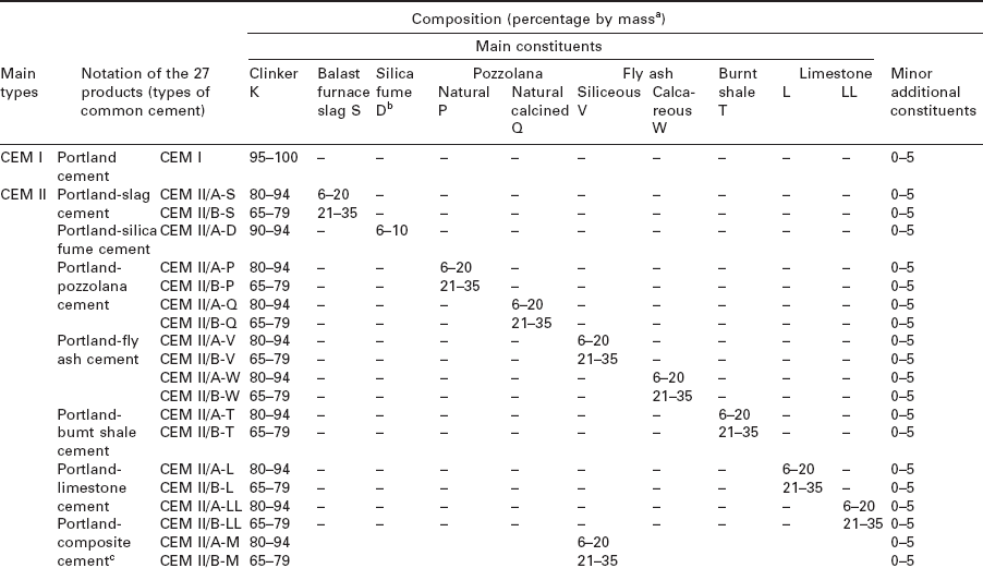
aThe values in the table refer to the sum of the main and minor additional constituents.
bThe proportion of silica fume is limited to 10%.
cIn Portland-composite cements CEMII/A-M and CEM ll/B-M, in pozzolanic cements CEMIV//A and CEMIV/B and in composite cements CEM V/A and CEM V/B the main constituents other than clinker are declared by designation of the cement.
adapted from BSi, 2000
For stabilised rammed earth white Portland cement is commonly preferred to grey ordinary Portland to preserve the natural colour of the soil. The addition of cement can be as high as 20%wt of dry soil, but is commonly used at ≤ 10%wt. In predominantly granular materials inter-particle bonding and interlock is achieved by the hardened cement paste surrounding and adhering to the aggregates. Cement stabilisation is therefore most effective on low cohesion soils, partly because it is difficult to ensure good distribution of the anhydrous stabiliser amongst cohesive clays (Bryan, 1988a, 1988b) and also because the larger granular particles can be surrounded and coated by the cement paste. In cohesive soils, many particles are smaller than anhydrous cement grains and thus are more difficult to coat. In cement–clay mixtures three different forms of reaction can occur (Burroughs, 2001; IPRF, 2005):
1. The hydration reaction forms cement gels on the surface of clay aggregations, and the hydrated lime (calcium hydroxide) that is freed during hydration reacts with silica and alumina in the clay minerals
2. Clay agglomerations are disaggregated by the hydration products and are penetrated by the resultant cement gels
3. Cement gels and the clay aggregates become intimately bonded. This results in both an inert sand–cement matrix and a matrix of stabilised clay in the new structure.
When Portland cement and water is added to soils, at the mixing stage a proportion of the clay particles that were coating the coarse aggregates can become detached and are dispersed into the aqueous phase. This has the effect of adjusting the exothermic hydration of cement paste and hence affecting both the setting time and the strength gain (IPRF, 2005). The remaining clay particles stay attached to the aggregate surfaces, which adjusts the interfacial transition zone (ITZ) at the cement paste–aggregate surface interface. The relative proportion of clay dispersed into the aqueous solution, and therefore becoming part of the hardened cement paste microstructure, depends upon the mineralogy and particle diameter of the clays. The detachment and dispersion of kaolinite clay, for example, is increased from 50% to 79% when the pH is raised from its natural value of 2 up to 12, when an alkaline substance such as cement is added. Further research is needed to determine the precise relationships between these factors. Previous research has shown that highly expansive clay minerals (e.g. Na-montmorillonite) suffer macroscopic swelling, which decreases the rate of hydration and reduces the rate of strength gain in cement-stabilised soils. Conversely, volumetrically stable clays with minimal swelling (e.g. kaolinite) or those with only crystalline swelling (e.g. Ca-montmorillonite) can increase the rate of hydration and strength gain in stabilised soils (IPRF, 2005).
9.3.1 Mechanical and durability performance
The unconfined compressive strength of cement stabilised compacted earth materials generally shows a non-proportional increase with the %wt of added Portland cement, as shown by Fig. 9.6.
9.6 Relative increase in compressive strength with cement content for different groups of soils (Houben and Guillaud, 1996).
Interestingly the relative increase in strength, with %wt of added cement, is much greater for soils with a lower specific surface area (e.g. sandy soils as opposed to silt or clay-rich soil). This is most likely due to the increased interfacial bonding between the cement paste and the aggregate. This may be due to the non-homogeneity of the microstructure, which has been observed to comprise (i) a cement-bound granular matrix, (ii) a dispersed and partially-stabilised cohesive matrix and (iii) a matrix of unstabilised material (IPRF, 2005). The degree of non-homogeneity is less for concrete materials that use washed aggregates, and the proportional increase in strength with additional %wt cement declines significantly for stabilised soils as the cohesive proportion of the soil increases. This was also observed through practical work conducted by Keable (1996).
This presents a problem in interpretation of research data, since three soils can exhibit different proportional increases in compressive strength with additional cement content. The solution can be to improve the particle size distribution and soil plasticity to make it more compatible with cement stabilisation and thus reduce both the %wt of stabiliser needed and also the cost per square metre of the mix. Cement stabilisation can provide cohesion in a low cohesion soil (thus enhancing strength and durability) or reduce the effective clay content of a very high clay soil (Middleton, 1987), and can also be used to reduce linear shrinkage and water absorption (Keable, 1996). King (1996) noted that excessive salts can often impair strength and lead to excessive efflorescing in soils that are to be stabilised with cement. When using cement stabilisation in earth walls it must be mixed with dry soil immediately prior to mixing, and the wall must be shaded and kept moist for at least seven days to allow adequate cement hydration.
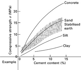
Previous research conducted by Hall and Djerbib (2004) compared the compressive strength of ten different soil types prior to stabilisation, which were found to exist between the range 0.7 and 1.5 N/mm2 as shown by Fig. 9.7. The soils were produced using identical aggregate and clay mineralogy, but with closely controlled particle size distributions (i.e. soil grading). This process of soil blending and characterisation is described in more detail in Hall and Djerbib (2004). The minimum compressive strength value for structural earth walls is given as 1.3 N/mm2 in the official document Materials and Workmanship for Earth Buildings by Standards New Zealand (1998). Middleton (1987) instead proposes a minimum compressive strength of 2 N/mm2. In a separate study, the addition of 3, 6 and 9%wt of CEM IIa ordinary Portland cement stabilisation was performed for three of the soils used by Hall and Djerbib selected as high, intermediate and low classifications of moisture absorption. Clearly the relative increase in compressive strength varies depending on soil grading and does not always follow a linear trend, as shown by Fig. 9.8.
9.7 The relationship between dry density and compressive strength for ten different unstabilised soil types (Hall and Djerbib, 2004).
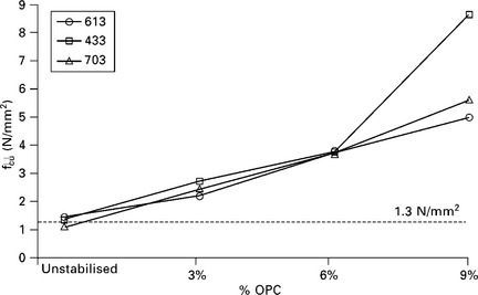
9.8 Relationship between cement content and compressive strength for three contrasting soil types (Hall, 2004).
Heathcote (1995) proposed that the ratio between wet and dry compressive strength of earth wall materials could be used as an indicator of the likely durability of the wall components. Based on the experiments he conducted it was concluded that a ratio of between 0.33 and 0.50 may be regarded as an indicator of a suitable level of durability dependent upon the severity of the rainfall to which the material is to be exposed. Walker (1995) has suggested that, as a measure of durability, the wet/dry strength ratio is likely to be approximate at best and certainly no substitute for real testing owing to the inherent variability of the material. Both the dry and saturated strength of cement stabilised soil blocks was improved with increased cement content and reduced clay content.
Figure 9.9 shows the comparison between an unstabilised specimen and a 6%wt cement stabilised specimen, made using exactly the same soil, after exposure to a 60-minute initial surface absorption (ISA) test, as defined by BS 1881-208 (1996). The unstabilised material (left) has suffered from loss of structural integrity because the increase in moisture content caused a loss of inter-particle friction and cohesion at the micro-structural level, whilst the stabilised specimen (right) has remained intact.
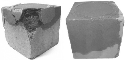
9.9 A visual comparison between an unstabilised rammed earth cube sample (left) and a 6% cement-stabilised rammed earth cube sample (right) after 1 h exposure to water absorption in an ISA test (Hall and Djerbib, 2005).
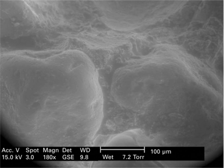
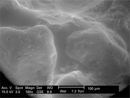
Analysis of the morphology of cement stabilised earth can be revealed using Scanning Electron Microscopy (SEM). The electron micrographs shown in Figs 9.10, 9.11 and 9.12 were taken using a Philips XL30 Environmental Scanning Electron Microscope with Field Emission Gun (ESEM-FEG) in wet mode using a Gaseous Secondary electron (GSE) Detector. The two larger particles are fine sand aggregates approximately 300 m in diameter, inter-connected with a hardened cement paste with clay mineral inclusions. As the partial vapour pressure was increased, the sample temperature was reduced to below the dew point temperature using a Peltier cooled stage. This method allowed direct control over the relative humidity and spontaneous formation of water droplets by surface condensation. As the moisture content increases, a water meniscus forms between the aggregate particles, some of which may be absorbed by the cement–clay matrix. The presence of moisture reduces inter-particle friction and hence the strength is reduced, however the microstructure remains intact due to the relatively strong interfacial bonding
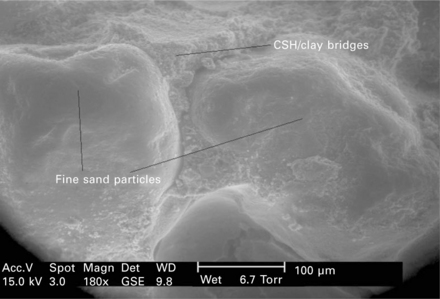
9.10 Electron micrograph of two fine sand particles interconnected with a clay–cement bridge (© 2006 Hall).
9.3.2 Moisture absorption and transport
Heathcote (1995) states that according to the Portland Cement Association stabilised soils are considered to have passed the ASTM D559 test for cyclic wetting and drying if the mass loss is less than 14% for well-graded sandy soils and 7% for clayey soils. Walker (1995) found that wetting and drying durability was improved with increased %wt cement stabilisation and by reduced clay content, the minerals of which appeared to disrupt the bonding action between the granular soil particles. For stabilisation with ≤ 10%wt cement, ASTM D559 is generally satisfied by soils having a plasticity index of 15–20%.
In relation to earth materials the height of a capillary wetting front in a clay soil, where the mean pore radius may be 0.5 m, would be 3 m compared with the height of a wet front height of around 100 mm in a fine sand with a mean pore radius of around 20 m (Allaby and Allaby, 1990). This clearly indicates the importance of particle size distribution for rammed earth materials in relation to the origins of moisture transport coefficients. The durability of many types of natural building stones has been related to pore size (BRE, 1983), where materials with high microporosity are often less durable than ones with a lower content of micropores. Other than the effect of wetting, the principal effect of rainfall is surface erosion due to the release of the kinetic energy associated with raindrop impact and dissolution (Heathcote, 1995). In previous research by Hall (2007), four stabilised rammed earth (SRE) test walls were successfully constructed and tested over four separate regimes in a climatic simulation chamber with realistic inner and outer wall conditions. The aim of the study was to evaluate the rate of moisture penetration and the likelihood of interstitial condensation when the walls were exposed to pressure-driven moisture ingress or temperature and humidity gradients. The study found that the SRE walls were able to far exceed the requirements for resistance to pressure-driven rainfall penetration based on BS 4315-2. Furthermore, after five days of exposure to pressure-driven rainfall ingress, there was no evidence of moisture penetration or significant surface erosion of the wall. It was also observed that no interstitial or internal wall surface condensation occurred despite no vapour barrier being installed and with exposure conditions of 20°C ± 1° and 40% relative humidity ± 5% (indoors) and 75% ± 5% outdoors varying at temperatures of + 8°C, 0°C and − 8°C. Measurements were taken using an embedded array of electronic sensors inside the walls and they detected no significant increase in the relative humidity or liquid moisture content of the test walls (Hall, 2007).
For freeze–thaw testing, the tests detailed in Houben and Guillaud (1996) and ASTM D 560 are apparently almost identical, and are tests originally designed and published for cement-stabilised soils in road design for the North American climate. Some authors consider that this may be ‘too severe’ for assessing walling material, however the experiments performed by Bryan (1988a, 1988b) showed that with cement stabilisation, clayey soils disrupted at all levels of cement content and compaction pressure, whilst sandy soils remained intact. According to Laycock (1997) the presence of salts affects the freezing process, and in times of high humidity the salts act to hold water hygroscopically to the surface of the material, thus ensuring better ice crystal growth where uncontaminated samples dehydrate to some extent during freezing.
9.4 Bituminous binders and emulsions
Bituminous materials have been in known use for thousands of years, when bitumen mastic was used in Mesopotamia as water proofing for reservoirs (Read and Whiteoak, 2003). Many years before crude oil exploration and its industrial processing began, man had recognised the numerous advantages of bitumen application and had started the production of bituminous materials found in natural deposits. As reported in the Shell Bitumen Handbook:
It is widely believed that the term bitumen originated in Sanskrit, where the word ‘jatu’ meaning pitch and ‘jatu-kirt’ meaning pitch creating referred to the pitch produced by some resinous trees. The Latin equivalent is claimed by some to be originally ‘gwitu-men’ (pertaining to pitch) and by others, pixtu-men (bubbling pitch), which was subsequently shortened to bitumen then passing via French to English.
BS 3690-1:1989 (BSi, 1989) defines bitumen as:
‘a viscous liquid, or solid, consisting essentially of hydrocarbons and their derivatives, which is soluble in trichloroethylene and is substantially nonvolatile and softens gradually when heated. It is black or brown in colour and possesses water proofing and adhesive properties. It is obtained by refinery processes from petroleum, and is also found as a natural deposit or as a component of naturally occurring asphalt, in which it is associated with mineral matter’.
Bitumen is a product of oil refining and is a long chain complex hydrocarbon. It typically contains 82–88% carbon and 8–11% hydrogen, the rest being sulfur, oxygen and nitrogen. There are four fractional components making up the chemical composition of bitumen (Read and Whiteoak, 2003):
1. Asphaltenes – these are insoluble in n-heptane, black or brown amorphous solids, fairly high molecular weight (1000–100,000), polar and their particle size is 5–30 nm. Asphaltenes constitute 5–25% of the bitumen.
2. Resins – these are soluble and play a key role in bitumen structure, acting as dispersing agents (peptisers) for asphaltenes. They are solid or semi-solid, polar, and have a particle size of 1–5 nm and their molecular weight is 500–50,000.
3. Aromatics – these constitute 40-65% of the total bitumen; they are a dark brown viscous liquid with high dissolving ability. Aromatics have the lowest molecular weight of 300–2000.
4. Saturates – these are white in colour and constitute 5–20% of bitumen. They are usually found in the waxy bitumen.
One of the drawbacks of bitumen is that it will only adhere to aggregate particles if that aggregate is heated sufficiently to drive off all moisture, and this is a costly and energy-intensive procedure. In order to overcome the problem and make the bitumen workable at ambient temperatures bituminous emulsions can provide a suitable solution. A bituminous emulsion is a dispersion of bitumen in water plus emulsifying agents. Hot bitumen will break into very small droplets, typically 1–20 m in size, by using a colloid mill. At the same time the emulsifying agent and water will be added to the hot bitumen (see Fig. 9.13). The emulsifier agent is a chemical with charge at one end, either positive or negative, and a long polymer tail with a strong affinity to bitumen, as illustrated by Fig. 9.14. When these emulsifier ions attach themselves to the bitumen droplets they are converted into charged particles. These charges are sufficient to prevent the droplets from coalescing, since bitumen and water have very similar specific gravities (1.00 and 1.03, respectively) and so the bitumen droplets float in the water.
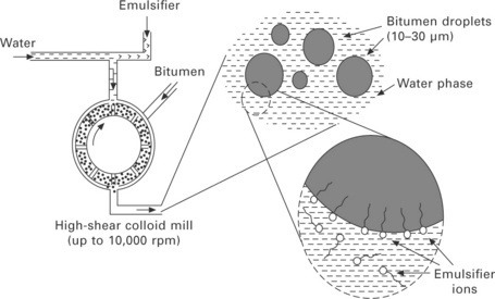
9.13 An illustration of the manufacture process for bituminous emulsion (Thom, 2008).
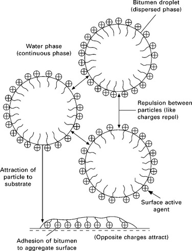
9.14 Schematic diagram of the surface charges on bitumen droplets (Read and Whiteoak, 2003).
Bituminous emulsions that are used in the UK are classified according to a three-part classification coding system. The first part of the code designates the emulsion as being either ‘A’ (for anionic) or ‘K’ (for cationic). The second part of the code is a number ranging from 1 to 4 that indicates the stability or breaking rate of the emulsion. Thus, the higher the number the more stable the emulsion. The third part of the emulsion classification code is a number that specifies the bitumen content of the emulsion. Thus, for example, a K1-70 emulsion means that it is a cationic emulsion, rapid-acting, with 70% by mass of residual bitumen (O’Flaherty, 2002).
The behaviour of bitumen stabilised materials (BSMs) is similar to that of unbound granular materials (e.g. earth materials), but with a significantly improved cohesive strength and reduced moisture sensitivity. The bitumen disperses only amongst the finest particles in BSMs, resulting in a bitumen-rich mortar between the coarse particles, and larger aggregate particles are not coated with bitumen. The benefits of bituminous emulsion for soil stabilisation can be summarised as follows (Asphalt Academy, 2009):
1. The BSMs could replace alternative high-quality materials in the upper layers of flooring, foundations or road construction due to the increase in strength associated with bitumen treatment
2. Lower quality aggregate or poorer soil grading can often be used
3. Improved durability, reduction in moisture sensitivity and the introduction of water-repellent properties
4. Reduction in temperature susceptibility compared to hot mix asphalts
Materials that are usually treated with bitumen are crushed stone of all rock types, natural gravels such as andesite, basalt, chert, diabase, dolerite, dolomite, granite, limestone, norite, quartz, sandstone, and pedogenoc materials such as laterite/ferricrete, and also reclaimed asphalt materials. The factors that must be taken into account for bituminous emulsion stabilised soil mixtures are as follows (Ibrahim, 1998):
1. Compatibility between the emulsion and the aggregate. Interfacial bonding between the emulsion droplets and the aggregates is strongly dependent on aggregate electro-charge. Mineral aggregates bearing a negative net surface charge (depending on pH), such as sandstone, siliceous gravel and granite, are often highly compatible with cationic bituminous emulsions. On the other hand, mineral aggregates such as limestone with a positive surface charge are often more compatible with anionic emulsions
2. Mixing consideration. The emulsion–soil combination, the amount of premixing water, and the mixing time are important factors to be considered in order to ensure a sufficient uniform dispersal of emulsion throughout the soil mixture. The amount of water needed for good dispersion is not the same for all emulsions. In fact cationic emulsions require additional mixing water in order to achieve a satisfactory coating (Ibrahim, 1998). As can be seen from Fig. 9.15, in the case of medium setting emulsion (MS), the coating is not improved by the presence of excess water; however, slow setting emulsion (SS) is improved by the presence of large amounts of added water.
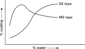
9.15 Comparison between the degree of aggregate coating vs. the amount of mixing water for medium and slow setting bituminous emulsions (Ibrahim, 1998).
3. Curing. Curing of bitumen soil mixtures is the process where the mixed and compacted layer discharges water through various mechanisms including evaporation, particle-charge repulsion and pore pressure-induced flow paths. Curing time, environmental conditions such as temperature and humidity, and the air voids in the mixture are therefore factors affecting the rate of moisture loss. According to Finn et al. (1968) and Marais and Tait (1989), the curing period may be as much as 6 months in dry climatic regions and two years in wet climates.
The mechanisms involved in the stabilisation of a soil with a bituminous material (usually hot bitumen, cutback bitumen, or anionic or cationic bitumen emulsion) are very different from those involved with cement or lime. The main function of the bitumen is to add cohesive strength to the soil. The unconfined compressive strength (UCS) test is typically performed on soils that are stabilised with additives (e.g. bitumen, cement, lime, etc.), as opposed to the triaxial test. In the UK, stabilised soils are normally tested using 150 mm cubes for coarse-grained and medium-grained materials; for fine-grained (passing through a 5-mm sieve) soil specimens having a height to diameter ratio of 2:1 is recommended. Before testing, stabilised samples are compacted to a pre-determined dry density, which is usually the maximum value obtained during the Proctor moisture-density test. Compaction is either by static (e.g. for fine-and medium-grained soils) or dynamic (e.g. for medium-and coarse-grained soils) techniques (O’Flaherty, 2002). Huan et al. (2010) measured the UCS of compacted soil stabilised with bitumen. They used different combinations of crushed granite and crushed limestone along with different percentages of Class 170 virgin bitumen. Their result showed that the sample of 75% CRB and 25% CLS with 3% foamed bitumen showed the highest UCS value at 254.5 kPa (Fig. 9.16).
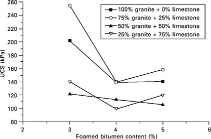
9.16 Plot of UCS versus foamed bitumen content for four different mixtures. Adapted from Huan et al., 2010
Marandi and Safapour (2009) investigated the use of combined stabilisers using Portland cement and bitumen emulsion with graded, granular material used for base courses in highways applications. The particle grading of these materials is typically the same as that for cement-rammed and is highly suitable for dynamic compaction techniques. They concluded that (i) the UCS increased with increase of %wt cement addition in the soil, and (ii) the UCS reached a maximum value when the bitumen emulsion was added at ~ 3%wt (see Fig. 9.17).
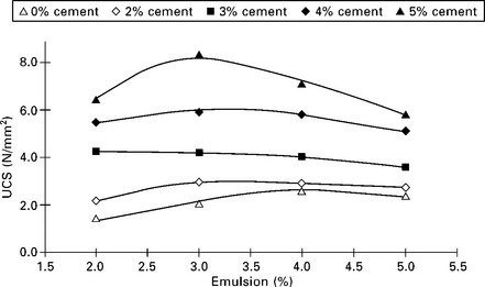
9.17 Twenty-eight-day UCS of combined cement/bitumen emulsion soil stabilisation (Marandi and Safapour, 2009).
9.5 Synthetic binders, polymers and adhesives
Several synthetic binders can be used for soil stabilisation instead of cement or hydrated limes including calcium sulfate dihydrate, commonly known as gypsum (CaSO4.H2O), tetrasodiumpyrophosphate (Na4.P2O7.10H2O), and calcium, sodium and potassium salts (Burroughs, 2001). In addition, several organic chemicals including fatty polyamides, lignin and casein can be used to enhance water repellence. Although polymers are relatively expensive compared with Portland cement and lime, for example, many different types are used as soil stabilisers. A large number of long-chain aliphatic and resin amines, amides and related cationic agents can be used for soil stabilisation (Burroughs, 2001). Polymers can be mixed with soil in the form of a liquid in order to fill the pores and harden the soil structure. In order for polymeric stabilisation to be used, the following requirements must be met:
• the polymer must have the ability to adhere to soil particles with the assistance of water (adhesive)
• it must be internally cohesive
• it must be capable of working sufficiently (polymerising) at high humidity and at low/non-elevated ambient temperatures
• it must be miscible with water to produce a low viscosity liquid.
Practically, polycondensational polymers are more suitable than polyadditional because (i) the method works even with large chains, (ii) when the polymerisation process stops, there are fewer possibilities for it to re-start and (iii) they are low cost and easy to prepare (Brandl, 1981; Coumoulos and Koryalos, 1983; Joshi et al, 1981). There are many types of polymers used for soil stabilisation including resorcinol-formaldehyde resin, phenol formaldehyde resin, furan resins, polyacrylates and polyurethanes. However, urea formaldehyde resins (UFR) are the most commonly used due to their low price compared with the others (Lahalih and Ahmed, 1998). Additionally, there is a possibility of creating hydrogen bonds between free hydroxyl groups and the soil (clay) alumino-silicates with the CO groups in UFR. This substance is mainly used with granular (i.e. sandy) soils, and is suitable for reducing the permeability and/or enhancing strength. It is applied either by pressurised injection or spraying depending upon whether it is being applied for surface or deep stabilisation. The main drawback in this stabilisation method is the brittleness of the material and the reduction in ductility. Therefore, when high plasticity soil is required, such as in connecting regions between concrete structures with differential settlement, UFR stabilisation is not the preferred method (Leva![]() i
i![]() and Bravar, 1990).
and Bravar, 1990).
9.6 Fibre reinforcement
Following the Second World War, soil stabilisation received increased attention to support overseas operations on rapid strengthening of weak soils to facilitate military traffic. Although cement and lime were still the common stabilising agent, innovation in non-traditional stabilising methods began, including fibre reinforcement, which can be used either alone or with conventional stabilising admixtures (Rafalko et al., 2007). Earth reinforcement techniques with fibres are used to improve the shear strength and stability of soils, often at concentrations of up to 1%wt of the soil. These composite soil–fibre materials have relatively high tensile strength and can be used in many application ranging from road structures to embankments and retaining structures (Jamshidi et al, 2010) as well as modern construction materials, as detailed in Chapter 20.
Recently, environmental concerns have led to increased interest in the utilisation of ‘alternative’ fibres, including solid waste and by-product materials, in soil reinforcement to improve the load-bearing capacity and durability of stabilised soil to use, for example, in retaining wall backfill and highway base layers. In addition to using raw materials as fibrous reinforcement armatures, alternative materials can be utilised as added-value materials in a variety of different shapes and textures, e.g. shredded, fibrous, sheets, smooth or rough, heavy- or lightweight, brittle or ductile, natural or synthetic, etc., whilst arising at lower cost and with less environmental impact (Jamshidi, 2010; Galán-Marin, 2010). To reduce the impact of natural disasters such as floods, landslides and earthquakes in susceptible areas, earth can be stabilised by fibre reinforcement to increase the shear strength of slopes as discussed in Chapter 19.
Soil fibre reinforcement is usually obtained by mixing the fibre to give random orientation within the soil structure. This can increase inter-particle cohesion and structural integrity by providing supporting armatures within the fabric creating a flexible structural mesh. The advantages of this technique are (i) different materials can be used as soil fibre reinforcement, (ii) there is minimal requirement for additional mixing machinery, (iii) recycled, waste and by-product fibres can be utilised, (iv) it is compatible with most soil types and (v) it can be applied over large soil volumes. The main limitations are that this technique can only be implemented at shallow depths, and also some fibres are biodegradable so can suffer from long-term performance degradation (Babu and Vasudevan, 2008). There are many different fibre types suitable for use in soil stabilisation (both natural and synthetic) including jute, sisal, bamboo, timber, cotton, glass, wool and shredded rubber fibre, as well as the following more common fibres types.
9.6.1 Polypropylene fibre (PP fibre)
Polypropylene (PP) fibres are manufactured in one of two main types: monofilament fibres that have a cylindrical shape and fibrillated fibres characterised by a flat, ‘tape-like’ shape which is susceptible to balling during the mixing process (Fletcher and Humphries, 1991). PP fibres are usually mixed with lime and/or cement-stabilised soils in order to decrease their brittleness and are added by up to 0.25%wt dry soil. The soil strength and toughness both increase with increasing %wt fibre content, whilst swelling and linear shrinkage is decreased (Cai et al., 2006; Tang et al., 2007).
9.6.2 Nylon fibres
The main use of nylon fibres is to enhance the ductility, durability and toughness of concrete, however a handful of investigations have also focused on applications in stabilising soils. Mixing nylon fibres with cement is expected to stabilise soil both mechanically and chemically due to its ability to absorb water and bond with the cement paste during curing (Rafalko et al., 2007; Zellers et al., 2002).
9.6.3 Poly(vinyl) alcohol (PVA) fibre
Poly(vinyl) alcohol (PVA) fibres are again commonly used in concrete to improve the ductile behaviour, but recently have started to be used in conjunction with cement-stabilised soils by taking advantage of the hydrogen bonds that can occur between cement particles and the hydroxyl groups. The main drawback to using this approach is that when the bond between PVA fibre and cement paste is extremely strong, rupture can occur rather than the preferred fibre pull-out mechanism, resulting in brittle failure of the composite. To overcome this disadvantage, PVA fibres can be submerged in an oiling agent before mixing to facilitate post-cracking fibre pull-out (Rafalko et al, 2007; Kanda and Li, 1998).
9.6.4 Natural fibres
Recently, palm fibre was used in soil stabilisation and was found to have the ability to absorb significant quantities of water (up to 187%). After 24 hours of soaking the fibre dimensions increased by 2.5% in length and 11.11% in cross-sectional area. The main use for this fibre is to improve the soil-bearing capacity, which can has been found to increase by up to 26 times in a silty sand (Marandi et al., 2008). Coir (coconut) fibre has a high tensile strength compared with other natural fibres, which exists even in wet conditions. It was found that up to 18% improvement in strength could be obtained when 2.5%wt (at 15 mm length) fibre is used for reinforcement of clays (Babu and Vasudevan, 2008).
9.7 Selection tool for modern stabilised earth construction
Burroughs (2001) developed a seven-stage flow chart of selection criteria for soil suitable for stabilisation for use in modern earth construction. It is the product of an extensive database of experimental data coupled with detailed analysis and validation. It enables the user to assess the suitability of a soil whilst minimising the need for independent (possibly expensive) experimental testing. Stage 1 involves identification of the provenance and availability of candidate materials (e.g. natural sub-soils, as-raised ballast or graded quarry waste). At this stage materials can be accepted or rejected based on initial screening for organic matter content (nominally ≤ 2%wt), which can be determined by loss on ignition, as well as high concentrations of contaminants such as sulfates, chlorides, etc. If the material is provisionally suitable then representative samples can be obtained for experimental testing. This begins at Stage 2 by characterisation of the linear shrinkage coefficient, the acceptance criteria for which are shown in Fig. 9.18.
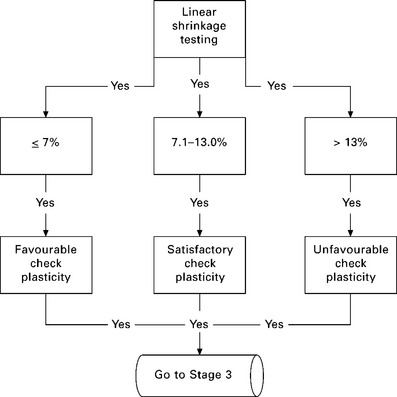
9.18 Stage 2 soil stabilisation selection criteria for linear shrinkage coefficient. adapted from Burroughs, 2001
Assuming that ‘favourable’ or ‘satisfactory’ linear shrinkage has been observed, Stage 3 involves the characterisation of the moisture contents at which the soil can be plastically deformed under load (i.e. non-elastic strain), known as the plastic limit (PL), and the moisture content at which the soil flows due to gravity known as the liquid limit (LL). The ratio between LL and PL is referred to as the plasticity index (PI), where the acceptance criteria for SRE materials are:
At Stage 4 the texture (or grading) of the soil is assessed by determining the particle size distribution. This can be achieved by a combination of wet sieve analysis for the granular fraction (i.e. particle diameters 0.063–20 mm +) and either sedimentation or laser particle analysis for cohesive fraction (i.e. sub-63 μm particle diameters), as explained in Chapter 6. The logic sequence and statistical likelihood of material suitability are shown in Fig. 9.19 where the acceptance criteria are as follows:
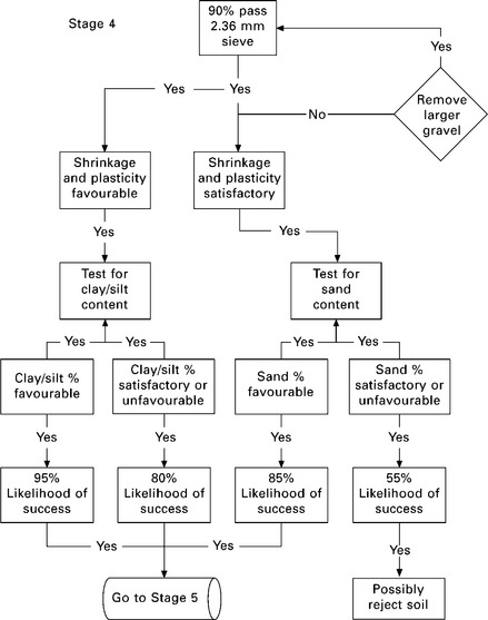
9.19 Stage 4 soil stabilisation selection criteria for particle size distribution. adapted from Burroughs, 2001
• favourable: cohesive fraction (silt + clay) 21–35%, or sand 30–65%, or gravel 3–5%
• satisfactory: silt + clay 36–45%, or sand 66–75%, or gravel 3–12%
• unfavourable: silt + clay < 21% or > 45%, or sand > 75%, or gravel < 3%.
The results of a previous study suggest that the physical characteristics of a soil are much more significant in determining the ‘success’ of stabilisation, for example in terms of the achievable mechanical strength and reduction in linear shrinkage, than is the exact %wt or type of added stabiliser. The Standards Australia HB195 The Australian Earth Building Handbook (Walker and Standards Australia, 2002), and also Houben and Guillaud (1996), suggest a generic approach whereby high-calcium lime stabilisation can be applied to soils with a high cohesive material content, whilst Portland cement is preferred for stabilisation of predominantly granular soils. The detailed study by Burroughs (2001) showed little experimental evidence to support these claims regarding grading and texture, and instead found statistically correlations between the type and %wt of stabilisation with both the shrinkage and the plasticity of the soil. This enabled the creation of the stabiliser selection criteria given in the chart in Fig. 9.20.
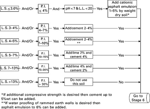
9.20 Decision chart for selection of soil stabiliser type and dosage rates. adapted from Burroughs, 2001
9.8 References
Akpokodje, E.G. The stabilization of some arid zone soils with cement and lime. Quarterly Journal of Engineering Geology and Hydrogeology. 1985; 18(2):173–180.
Allaby, A., Allaby, M. The Concise Oxford Dictionary of Earth Sciences, 1990. [Oxford].
Asphalt Academy. Technical Guideline: Bitumen Stabilised Materials – a Guideline for the Design and Construction of Bitumen Emulsion and Foamed Bitumen Stabilised Materials– Second Edition. Pretoria, South Africa: Asphalt Academy, 2009.
Babu, G.L.S., Vasudevan, A.K. Strength and stiffness response of coir fiber-reinforced tropical soil. Journal of Materials in Civil Engineering. 2008; 20(9):571–577.
Bell, F.G. Lime stabilization of clay minerals and soils. Engineering Geology. 1996; 42(4):223–237.
Brandl, H., Alteraction of soil parameters by stabilization with lime. Proceedings of the 10th International Conference of Soil Mechanics and Foundations Engineering, 1981. [Stockholm, Vol 3, pp. 587–594].
BREBRE Digest 269: The Selection of Natural Building Stone. London: HMSO, 1983.
Bryan, A.J. Criteria for the suitability of soil for cement stabilisation. Building and Environment. 1988; 23(4):309–319.
Bryan, A.J. Soil/cement as a walling material – I: stress/strain properties. Building and Environment. 1988; 23(4):321–330.
BSi, Bitumens for building and civil engineering: specification for bitumens for roads and other paved areas. British Standards Institute, London, 1989. [BS 3690-1: 1989 + A2:2008 –].
BSi, Testing concrete – Part 208: recommendations for the determination of the initial surface absorption of concrete. British Standards Institute, London, 1996. [BS 1881-208: 1996].
BSi, Cement–composition, specifications and conformity criteria for low heat common cements. British Standards Institute, London, 2000. [BS EN 197-1 2000].
Burroughs, V.S., Quantitative criteria for the selection and stabilisation of soils for rammed earth wall constructionPhD thesis. Australia: University of New South Wales, 2001.
Cai, Y., Shi, B., Ng, C.W.W., Tang, C.S. Effect of polypropylene fibre and lime admixture on engineering properties of clayey soil. Engineering Geology. 2006; 87(3–4):230–240.
Coumoulos, D.G., Koryalos, I.P., Grout mixtures for ground improvement – laboratory testing and quality control. Proceedings of the VIII European Conference of Soil Mechanics and Foundation Engineering, 1983. [23–26 May, Helsinki].
Domone, P.L.J., Illston, J.M. Construction Materials: Their Nature and Behaviour. Abingdon: Spon Press; 2010.
Finn, F.N., Hicks, R.G., Kari, W.J., Coyne, L.D. Design of emulsified asphalt treated bases. Highway Research Record. 239, 1968.
Fletcher, C.S., Humphries, W.K. California bearing ratio improvement of remolded soils by the addition of polypropylene fiber reinforcement. Journal of the Transportation Research Board. 1991; 1295:80–86.
Galán-Marin, C., Rivera-Gómez, C., Petric, J. Clay-based composite stabilized with natural polymer and fibre. Construction and Building Materials. 2010; 24(8):1462–1468.
Hall, M.R., The mechanisms of moisture ingress and migration in rammed earth wallsPhD thesis. UK: Sheffield Hallam University, 2004.
Hall, M. Assessing the environmental performance of stabilised rammed earth (SRE) walls using a climatic simulation chamber. Building and Environment. 2007; 42(1):139–145.
Hall, M., Djerbib, Y. Rammed earth sample production: context, recommendations and consistency. Construction and Building Materials. 2004; 18(4):281–286.
Hall, M., Djerbib, Y. Moisture ingress in rammed earth: part 2 – the effect of particle-size distribution on the rate of static pressure-driven moisture ingress. Construction and Building Materials. 2005; 20(6):374–383.
Heathcote, K.A. Durability of earth wall buildings. Construction and Building Materials. 1995; 9(3):185–189.
Houben, H., Guillaud, H. Earth Construction – A Comprehensive Guide: Second Edition. London: Intermediate Technology Publications; 1996.
Huan, Y., Siripun, K., Jitsagiam, P., Nikraz, H. A Preliminary study on foamed bitumen stabilisation for western Australian pavements. Scientific Research and Essays. 2010; 5(23):3687–3700.
Ibrahim, H.E.M., Assessment and design of emulsion-aggregate mixtures for use in pavementsPhD thesis. UK: University of Nottingham, 1998.
IPRF, Effects of coarse aggregate clay coatings on concrete performance. Technical report IPRF-01-G-002-01-4.2, 2005. [Innovative Pavement Research Foundation, Skokie, IL, USA].
Jamshidi, R., Towhata, I., Ghiassian, H., Tabarsa, A.R. Experimental evaluation of dynamic deformation characteristics of sheet pile retaining walls with fiber reinforced backfill. Soil Dynamics and Earthquake Engineering. 2010; 30(6):438–446.
Joshi, R.C., Natt, G.S., Wright, P.J., Soil improvement by lime-fly ash slurry injection. Proceedings of the 10th International Conference of Soil Mechanics and Foundations Engineering, 1981. [15–19 June, Stockholm].
Kanda, T., Li, V.C. Interface property and apparent strength of high-strength hydrophilic fiber in cement matrix. Journal of Materials in Civil Engineering. 1998; 10(1):5–13.
Keable, J. Rammed Earth Structures: A Code of Practice. London: Intermediate Technology Publications; 1996.
King, B. Buildings of Earth and Straw – Structural Design for Rammed Earth and Straw Bale Architecture. USA: Ecological Design Press; 1996.
Lahalih, S.M., Ahmed, N. Effect of new stabilizers on the compressive strength of dune sand. Construction and Building Materials. 1998; 12(6–7):321–328.
Laycock, E.A., Frost degradation and weathering of the magnesian limestone building stone of the Yorkshire provincePhD thesis. UK: University of Sheffield, 1997.
Leva![]() i
i![]() , E., Bravar, M. Soil stabilization by means of "LENDUR EH" ureaformaldehyde resin. The Mining-Geological-Petroleum Engineering Bulletin. 1990; 2(1):137–143.
, E., Bravar, M. Soil stabilization by means of "LENDUR EH" ureaformaldehyde resin. The Mining-Geological-Petroleum Engineering Bulletin. 1990; 2(1):137–143.
Marandi, S.M., Safapour, P. Base course modification through stabilization using cement and bitumen. American Journal of Applied Sciences. 2009; 6(1):30–42.
Marandi, S.M., Bagheripour, M.H., Rahgozar, R., Marandi, H.Z. Strength and ductility of randomly distributed palm fibers reinforced silty-sand soils. American Journal of Applied Sciences. 2008; 5(3):209–220.
Marais, C.P., Tait, M.I., Pavements with bitumen emulsion treated bases: proposed material specifications, mix design criteria and structured design procedures for southern African conditions. Proceedings of the 5th Conference on Asphalt Pavements for Southern Africa, 1989. [5–9 June 1989, Royal Swazi Convention Centre, Swaziland].
Middleton, G.F. Bulletin 5 – Earth Wall Construction: Fourth Edition. Chatswood, Australia: National Building Technology Centre; 1987.
Neville, A.M. Properties of Concrete – 4th Edition. Essex, UK: Pearson; 1995.
O’Flaherty, C.A.Highways: the Location, Design, Construction and Maintenance of Road Pavements. Oxford: Butterworth-Heinemann, 2002.
Rafalko, S.D., Brandon, T.L., Filz, G.M., Mitchell, J.K. Fiber reinforcement for rapid stabilization of soft clay soils. Transportation Research Record. 2007; 2026:21–29.
Read, J., Whiteoak, D. The Shell Bitumen Handbook – 5th Edition. London: Thomas Telford; 2003.
Reddy, B.V.V., Lokras, S.S. Steam-cured stabilised soil blocks for masonry construction. Energy and Buildings. 1998; 29:29–33.
Standards New Zealand. NZS 4298: 1998 Materials and Workmanship for Earth Buildings. Wellington, New Zealand: Standards New Zealand; 1998.
Tang, C., Shi, B., Gao, W., Chen, F., Cai, Y. Strength and mechanical behavior of short polypropylene fiber reinforced and cement stabilized clayey soil. Geotextiles and Geomembranes. 2007; 25(3):194–202.
Thom, N.H. Principles of Pavement Engineering. London: Thomas Telford; 2008.
Walker, P., Standards Australia. HB 195 The Australian Earth Building Handbook. Sydney: Standards Australia International; 2002.
Walker, P.J. Strength, durability and shrinkage characteristics of cement stabilised soil blocks. Cement and Concrete Composites. 1995; 17(4):301–310.
Zellers, B., RCN Inc., Nycon nylon fibers add to hydration efficiency of cement available from. 2002. accessed: 3 December 2010 www.nycon.com/techpapers/