
Pneumatically impacted stabilized earth (PISE) construction techniques
Abstract:
This chapter describes an industrialized method for constructing monolithic reinforced cement-stabilized earth walls. The process utilizes high-pressure air to impact a carefully selected blend of mineral aggregates against an open form. Pneumatically impacted stabilized earth (PISE) differs from rammed earth in that only one face of the formwork is required and the material is placed at higher water content. The method utilizes equipment designed and manufactured for the shotcrete industry.
15.1 Introduction
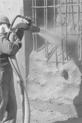
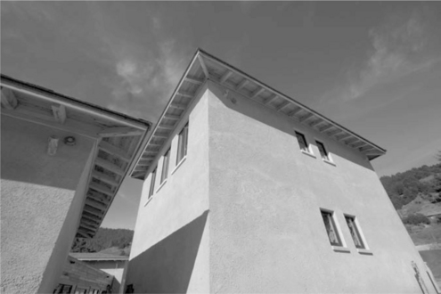
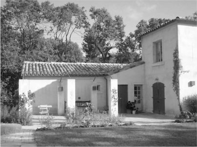
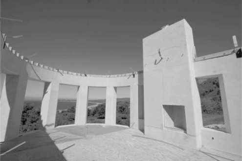
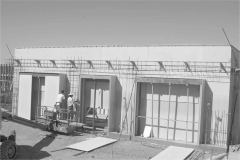
PISE, an acronym for pneumatically impacted stabilized earth, is a process for constructing stabilized earth walls using high-pressure air for delivery and placement (see Fig. 15.1); procedures and equipment are similar to dry-mix shotcrete (or gunite). A carefully selected, tested and proportioned mixture of soil and cement is blended and then conveyed via high-pressure air to the point of placement. Water for hydration is added to the dry materials at the nozzle. The force of impact at the point of placement in conjunction with stabilization contributes to ultimate strength. Like traditional rammed earth, the end product is a monolithic structural wall (see Figs 15.2, 15.3 and 15.4). PISE differs from rammed earth in that only one side of the formwork is required and the finished surfaces have a different texture.
This chapter will cover several aspects of PISE installations for new construction including materials, equipment, crew qualifications and organization, preliminary preparation, proportioning, placement and quality control. The techniques and procedures described herein are based on 20 years of technological development and construction implementation by the author in conjunction with experienced gunite installers. It should be remembered however that as the technology gains in popularity and migrates to different geographical regions, procedures may vary from one region to another, and adjustments may be required to meet the needs of the particular project. Most importantly, mix designs will significantly differ from one geographical region to another, depending on available mineral soils. Due to this range of suitable soil types, the reader must be warned that substantial pre-construction testing will be necessary in all cases before undertaking a project of any significant size.
15.2 Materials used for pneumatically impacted stabilized earth (PISE) construction
PISE mix designs are composed of mineral soil, supplemental aggregate, cementitious binders, water and, in some cases, one or more admixtures such as fly ash, fibers or other components.
15.2.1 Mineral soils
All soil materials selected for PISE construction must be free from organic matter and contain a relatively uniform distribution of coarse and fine aggregates, ranging from 1/2″ gravel to fine silt and clay.
A wide variation in particle size improves the strength, durability, and resistance to shrinking of the in-place PISE. The maximum size aggregate should be 1/2″ and, for best results, no more than 15% should pass through a 200-mesh sieve. A grain size distribution table of a soil that has demonstrated good results for PISE work is shown in Table 15.1.
Table 15.1
| Sieve size | % Passing |
| 1/2″ | 100 |
| 3/8″ | 97 |
| #4 | 77 |
| #8 | 54 |
| #16 | 38 |
| #30 | 29 |
| #50 | 22 |
| #100 | 18 |
| #200 | 15 |
Particular attention must be paid to the expansive characteristics of the fine particle constituent in order to reduce shrinkage cracking. In general, soils with a plasticity index of less than 10 will achieve better in-place results. The plasticity index of the aggregate blend can be reduced through the addition of sand or small aggregate.
Laboratory testing of the proposed mineral soils will provide information on the gradation and plasticity index. Based on these results, the type and percentage of aggregate admixtures can be determined. Clean coarse sand is a commonly available and suitable admixture, providing both strength and crack control.
It should be mentioned that the mix design requirements for PISE are much more restrictive than for traditional rammed earth. Maximum aggregate size is restricted to 5/8″ and clay content to 15%. Water content is significantly higher, resulting in greater likelihood of shrinkage cracking. Pre-construction testing and careful mix design formulation are of paramount importance in order to achieve optimum results.
15.2.2 Supplemental aggregates
In situations where either the gradation or the plasticity index of the selected mineral soil does not fall within the range of acceptability, supplemental aggregates will be required. These aggregate amendments are most often coarse sand or small gravel. They are selected based on size, shape, color, cost and proximity to the construction site. In some cases a combination of sand and gravel from separate sources will provide the best results. Predicting results based on laboratory formulations is possible although not nearly as reliable as shooting pre-construction test panels.
15.2.3 Cement (binder)
Cements used for stabilizing mineral soils are the same as those used in concrete mix designs: Portland cement types I, II and III; white cement and block cements. In PISE construction, the selection of which cement to use is normally based on the desired color of the finished wall, rather than the structural qualities, as ultimate strength requirements are generally low compared to concrete. Fly ash may be combined with cement in some mix designs to reduce the dependence on virgin cement and to improve the workability and resistance to cracking of the finished PISE. At the time of writing, only limited experimentation had been undertaken with cement/fly ash mix designs.
15.2.4 Water
Mixing water should be clean and free from substances which may be injurious to concrete or steel. It is recommended that potable water be used. Curing water should be free from substances that may be injurious to concrete. Water for curing of architectural PISE should be free from elements that will cause staining.
15.3 The forming system
Formwork for PISE differs significantly from that for traditional rammed earth in that the form is open on one face (see Fig. 15.5). The principle component of the PISE form is the backer. This establishes the dimensions, plane and elevation of the wall. The backer may be of any rigid material, such as wood, steel, rigid insulation board, expanded metal lath, straw bales or an excavated cut bank.
In conjunction with the backer (or panel), shut-offs establish the end of a wall and block-outs create openings for doors and windows. The top of the form is left open, with a thin wooden ledger (or screed) attached as a guide to define the finished wall height. Shut-offs and block-outs are typically cut to the width of the finished wall. In all cases, the forms must be adequately braced and secured to prevent excessive vibration or deflection during placement of the PISE. All formwork must be designed to provide for the escape of compressed air and rebound during installation. For column construction, two sides can be formed or the four corners can be formed using light narrow wood lath. Similarly, in beam construction, the soffit and one side may be formed leaving the other sides open. Beams should be braced or shored so that no deflection will occur due to the weight of fresh PISE.
15.3.1 Simple forming
There are many different methods for constructing a plywood form. The most common are wood framing, pre-fabricated form panels, manufactured aluminum concrete forming systems, sheet metal studs or custom framing components. The method shown in the accompanying photographs illustrates conventional wood framing, in which a 2 × 4 frame wall is built on the slab, fixed into place along the inside wall line, then sheeted with the backing material (in this case 3/4″ HDO plywood). Forms for the entire perimeter of the roughly 30 × 50 foot room were set to full wall height, eliminating the need for shut-offs. Block-outs for doors and windows were built and braced with 2 × 4 s and 2 × 6 s. The project illustrated took a crew of three men ten days to erect. One advantage to setting forms using a frame wall approach is that plywood sheets can be cut and fit into a seam pattern that can correlate to interior room details or to the placement of windows or other significant architectural elements. Another advantage is that the lumber used to build the frame can be reused elsewhere in the house. A disadvantage to setting plywood against a frame is that disassembly is more time-consuming. The 2 × 4 s are levered away from the plywood, protruding nails nipped off and the sheets taken down carefully one at a time.
15.3.2 Alternative forming systems
Alternative forming systems such as pre-constructed plywood panels, manufactured concrete forming panels, or custom built forms have their own set of advantages and disadvantages. These relate to cost, speed of assembly and disassembly, and likelihood of reuse. In a large project where the PISE walls will be shot in several sections, a reusable form will normally prove more economical.
In order to make an informed decision regarding which form system to use, four factors should be considered: experience and skills of the crew, cost of a rented system versus purchase price of new materials, opportunity to reuse framing lumber and plywood in the project and finally opportunity to reuse form panels in a future project.
15.4 Reinforcement of pneumatically impacted stabilized earth (PISE) walls
Reinforcing bars or welded wire mesh are generally required in all PISE structures subject to lateral loading, although in some instances, low width to height ratios (less than 1:4.5) may justify a mass wall (unreinforced) design. Where the risk of seismic activity is low, reinforcing can be significantly reduced. Generally reinforcing can be lighter in a PISE wall than in a concrete wall because the high mass of PISE (as in all earthwall structures) provides an inherent resistance to lateral movement. PISE walls have the ability to absorb energy without breaking.
For thin (3″ or less) applications such as veneers over concrete or straw bale, reinforcement in the form of welded wire fabric or stucco wire is recommended. Wire mesh limits the development and depth of cracking resulting from shrinkage and temperature stresses.
To produce uniform walls, reinforcing should be designed and positioned to cause the least interference with the placement of the PISE. Normally no bars larger than 5/8″ in diameter (number 5 rebar) should be used. If larger sizes are required by the design, exceptional care must be taken to properly encase them with PISE. In all cases, reinforcing should be sized, spaced and arranged to facilitate the placement of PISE and to minimize the development of voids or shadowing. Lapped bars should be spaced apart at least three times the bar diameter. For most PISE applications, one layer of reinforcing is usually sufficient. Where additional layers are specified, spacing and positioning of the bars must allow for penetration of the PISE to the deepest recesses. The minimum cover over reinforcing should comply with the job specification, but should never be less than 2″.
Reinforcing should be rigidly secured in place to prevent its movement or deflection. Vibrations in the reinforcing steel can cause sagging and dropouts, reducing the in-place strength and adversely affecting the cosmetic quality of the PISE. Reinforcing should be free of oil, rust, dirt or any substance that could impair good bonding.
15.4.1 Embedded ledgers, hardware and conduits
Wooden or steel ledgers, hardware such as J-bolts, beam brackets, purlin anchors and straps or conduits, chases, electrical boxes and plumbing mounts may be installed directly in PISE walls. In every case the embedded devices must be securely fastened in place prior to installation so as to prevent movement or misalignment due to the force of impact. Electrical boxes and plumbing ends should be taped shut or otherwise protected against filling with overspray. Exposed threads on bolts should be taped or sleeved. Conduits and plumbing lines should be installed to provide for a minimum of 3″ of cover.
15.5 Equipment for proportioning, mixing and placement
The successful installation of PISE requires properly operated and maintained equipment. The contractor should choose the equipment for a project only after careful evaluation of the specifications, size and character of the work, job site conditions, the availability and quality of local materials, labor, and time available. A basic complement of equipment for PISE usually consists of, but is not limited to, the mixing equipment, air compressor, delivery equipment (gun) and the required hoses and nozzles.
15.5.1 Mixing equipment
Most PISE operations utilize portable mixing equipment set up on the job. This can be either batch (or drum) mixers or continuous auger mixers. Auger mixers are more capable of providing a continuous and consistent supply of material. Small continuous mixers are generally comprised of a single 1–3 cubic yard soil hopper, fed by tractor bucket, and a smaller hopper for cement, supplied one sack at a time. Larger volumetric mixers normally have two hoppers, each 3–5 cubic yards, and a cement hopper with a 3000-pound (30-sack) capacity. In both types, the soil and cement are metered into the mixing trough where the auger combines the dry ingredients as it moves material to the outfall. Water required for pre-dampening is added in the mixing trough. The equipment should have adequate controls and gauges to allow the operator to adjust mix ratios as required to assure compliance with the specified mix design. Some volumetric mixing machines are equipped with liquid admixture systems.
15.5.2 Air requirements
A properly operating air compressor of ample capacity is essential to a satisfactory PISE operation. The compressor should maintain a supply of clean, dry, oil-free air adequate for maintaining required nozzle velocities while simultaneously operating all air-driven equipment, and a blowpipe for clearing away rebound. Operation of compressors at higher elevations requires increased volumes of air. Compressed air requirements vary depending on the type of equipment, its condition and mode of operation. Check the gun manufacturer’s recommendations for required compressor capacity. The compressor capacities shown in Table 15.2 are a general guide for PISE applications using air-motor driven continuous feed guns. These air capacities must be adjusted for compressor age, altitude, hose and gun leaks, and other factors that reduce the rated capacity of the air compressor. In addition, hose length, unit weight of material, bends and kinks in the hose, height of nozzle above the gun and other air demands, will all affect the air requirements of a particular equipment layout.

The operating air pressure is the pressure driving the material from the gun into the hose and is measured at the material outlet or air inlet on the gun. The operating pressure varies directly with the hose length, the specific weight of the materials mix, the height of the nozzle above the gun, the number of hose bends and other factors. A rule of thumb is that operating pressures should not be less than 40 psi (275 kPa) when 100 ft (30 m) or less of material hose is used, and the pressure should be increased 5 psi (35 kPa) for each additional 50 ft (15 m) of hose and 5 psi (35 kPa) for each additional 25 ft (8 m) the nozzle is above the gun.
15.5.3 Delivery equipment
Although there are several types of delivery equipment used for dry-mix shotcrete, the rotary gun is the most common for PISE construction. It is designed to provide a continuous supply of dry mixed material through the delivery hose to the nozzle. Basically, a feed bowl comprising a number of U-shaped pockets rotates beneath a material hopper. As each pocket in turn passes below the air supply, material is forced out of the pocket, through the outlet neck and into the hose. Continuous rotation of the bowl and continuous discharge of material under pressure provides the force required to move material through the delivery hose to the nozzle. The internal configuration of the gun may vary somewhat between manufacturers, but all types rely on the same principle and utilize a machined steel wear plate and replaceable rubber wear pads. Proper functioning of the gun depends on proper service and adjustment of the plate and pads.
15.5.4 Hoses
All of the hoses used to convey air, water and dry material should be of the highest quality and inspected regularly for worn spots. Material hoses are particularly susceptible to wear and should be replaced well in advance of failure. Water hoses and small air hoses for auxiliary uses should be commercial grade. Hoses should be properly sized to minimize friction loss in the line. Material delivery hoses and the air hose connecting the compressor to the gun typically have internal diameters of 2″.
15.5.5 Nozzle
The nozzle attaches to the end of the delivery hose and is composed of the body, water ring, water valve and nozzle liner. The most efficient nozzle type for PISE construction is the standard gunite nozzle (distributed by Ridley as the 700–902). The water ring should be checked periodically to ensure uniform flow, and the nozzle liner should be replaced as needed.
15.5.6 Auxiliary equipment
Other components in a complete PISE equipment package include an in-line water booster pump for situations where water pressure is inadequate; a blow pipe for removing rebound and overspray; an air-driven impact chisel for cleaning the bowl and gooseneck; a small sledge hammer for freeing clogged lines; and a full complement of hose and valve repair parts.
15.6 The pneumatically impacted stabilized earth (PISE) method
The quality of PISE installation depends on the successful integration of several factors and individuals: the gun operator, nozzleman, control of mixing water, nozzle velocity and nozzle technique. In each case, the expertise and experience of the responsible crew member determines the quality of operation.
15.6.1 Control of mix water
In placing PISE just enough mix water is added at the nozzle so that the surface of the in-place material has a slight gloss. The nozzleman can change the water content instantaneously by as little or as much as needed. Depending on the position of the work, too much water can cause the PISE to sag, slough, puddle or drop out. Dropouts can occur in overhead work where too much material is gunned or ‘hung’ in one location at one time. TOO little water leaves a dry, dark, coarse surface with no gloss. This condition increases rebound, creates dry pockets, makes finishing more difficult and can produce weak and laminated PISE. For effective water control, the water pressure at the nozzle should be 15–30 psi (103–207 kPa) over the air pressure.
15.6.2 Nozzle velocity
The velocity of the material at impact is an important factor in determining the ultimate properties of PISE. For most installations where standard nozzle distances of 2 to 6 ft (0.6 to 1.8 m) are used, material velocity at the nozzle and impact velocity of the material particles are almost identical. At longer nozzle distances they may differ and it may be necessary to increase the nozzle velocity so that the impact velocity will suit the requirements of the installation. Consideration must also be given to the fact that increasing velocity means increasing rebound.
The factors that determine material velocity at the nozzle are volume and pressure of available air, hose diameter and length, size of nozzle tip, type of material and the rate it is being gunned. These factors allow for great flexibility and versatility in that large, intermediate or small volumes of material can be gunned at low, medium and high velocities according to the immediate needs of the application. Small or large variations in flow, water content and velocity can be made by the gunman on instruction from the nozzleman.
15.6.3 Gun operation
Proper gun operation is critical to ensure a smooth, steady flow of material through the hose and nozzle. If a suitable balance of air and material flow is not maintained, slugging, plug-ups or excessive rebound may occur. Pulsating and intermittent flow causes under- or overwetting of the mix and requires the nozzleman to quickly adjust the water, manipulate the nozzle, direct it away from the work or stop.
Whenever possible, sections should be gunned to their full design thickness in one layer to reduce the possibility of internal cold joints and laminations. The exception to shooting full thickness would only be in cases where a thin (less than 1″) flash coat is required to achieve cosmetic uniformity. The distance of the nozzle from the work, usually between 2 and 6 ft (0.6–1.8 m) should be such that it gives best results for work requirements. As a general rule, the nozzle should be held downward toward the work at an angle between 30 and 45°. Steeper angles result in excessive rebound. When gunning tops of walls, steeper angles are acceptable to reduce overspray, and when gunning flash coats and other veneer type work, a nozzle angle perpendicular to the wall will be most effective.
To uniformly place the PISE and achieve good compaction, the nozzle is directed slightly downward and rotated steadily in a series of small oval or circular patterns. Waving the nozzle quickly back and forth changes the angle of impact, wastes material, increases overspray and results in a rougher surface that creates more work for the finisher. An exception to small circular patterns would be when gunning to encase heavy rebar configurations, in which case the nozzle must be moved from side to side to direct material behind the bars. Also, the mix should be wetter than normal to aid the PISE in flowing to the backside and to prevent build-up on the front face of the bar.
When shooting PISE for thick structural walls, application should begin at the bottom against the form face. The first layer should fully encase the reinforcement and care should be taken to prevent overspray building up higher on the form face than the defined work area. An effective technique for shooting thick walls is ‘shelf’ or ‘bench’ gunning. Instead of gunning the full thickness of the wall with a horizontal top, a thick layer of material is built up, the top surface of which is maintained at approximately a 45° slope. With this technique, rebound is less likely to be trapped in the wall as the loose material is free to fall downslope, and compaction is improved as the nozzle angle will be perpendicular to the surface receiving PISE.
When inside corners, door or window block-outs, or other projections are part of the area to be shot, they should be gunned first and continuously built up as the layers become higher. This will prevent rebound and overspray from filling the corners and being covered up. Slight overwetting of the initial layer helps bond and reduces rebound. on top of door or window headers it is particularly important that rebound and other loose material be cleaned off before shooting. Prior to gunning, use a jet of air from the nozzle or a blowpipe to clean horizontal surfaces.
15.6.4 Rebound and overspray
Two of the unwanted by-products of PISE construction are rebound and overspray. These can be minimized with proper mix formulation and nozzle expertise. Overspray is the material disbursed away from the receiving surface. It adheres to guide wires, forms, reinforcing steel and other projections, leaving an unconsolidated thickness of low-quality PISE. It should be removed, preferably before it hardens, especially in areas to be covered with fresh PISE. Shooting fresh PISE on top of overspray left on rebar or anchor bolts will decrease the bond strength. Overspray left on formwork can cause delamination or other unwanted cosmetic defects when forms are removed.
Rebound is the term used both for the portion of mix that ricochets off the surface during shooting and the excess material that is shaved off the wall during screeding (trimming). The amount of rebound that results depends on several factors: percentage of fines in the mix design, percentage of cement stabilization, moisture content, thickness of the work, air pressure, nozzle angle and nozzle technique. Nozzle technique is especially important to minimize the overshot material that must be cut back by the finisher.
Rebound should not be reused in the structural wall, but can be salvaged and used for other applications on the job site, such as rammed earth garden or patio walls, heavy blocks for low retaining walls, paths, paving or other applications. Because the amount of rebound generated can be as much as 25% of the total volume of material placed, it is financially and environmentally imperative that some plan for utilization of rebound be in place prior to beginning wall construction. With a rebound utilization program, valuable by-products can result as opposed to the generation of a waste material needed to be off-hauled and disposed of.
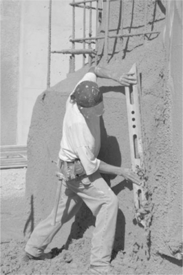
15.6.5 Finishing
The most common technique for finishing a PISE wall is to shoot a fraction of an inch beyond the guide wires and then shave the excess material off to a straight and uniform finish (see Fig. 15.6). Care must be taken by the finisher to maintain a consistency to his rodding technique. Although there are other finishing techniques, the rough rod finish has the advantages of hiding hairline cracking and other surface inconsistencies.
Other finishes for PISE walls include the gun or natural finish and the smooth or steel trowel finish. The natural finish is that left by the nozzle after the wall has been brought to approximate finish grade but not rodded. A gun finish is textured and uneven. In some cases small craters created by the aggregate burying itself in the wet mix can leave the wall with an unattractive ‘moon surface’ finish. The expertise of the nozzleman is essential in order to achieve an acceptable natural finish.
A smooth finish is obtained by first shooting a slightly wetter ‘flash’ coat, approximately 1/4″ thick, over the wall surface after it has been rodded flat. The fresh surface should first be finished with a wood float to achieve a uniform granular finish, then finished again with steel plastering or pool trowels. Because of the small aggregate in the PISE mix, a high-quality smooth finish is difficult to achieve and requires considerably more effort than the rodded wall. It is also subject to cracking and checking. It is recommended that small samples of smooth wall be created for approval prior to undertaking a large wall area.
15.6.6 Curing
Wall forms should be left in place for a minimum of 12 hours prior to stripping. Door and window jambs should remain in place for a minimum of 36 hours. Headers and beam forms should be left in placed and braced for a minimum of seven days.
All PISE should be properly cured so that its potential strength and durability are fully developed. This is particularly true for thin sections and veneers. For thick walls, curing will naturally take place more slowly as the moisture within the mass of the wall will contribute to the curing process. When conditions are cool or damp, the mass of the wall may be sufficient to retard moisture loss from the wall with no additional curing measures. In hot, dry or windy conditions, the walls should be sprayed with water several times per day or wrapped with plastic or other tarps to trap moisture. Curing conditions should be maintained for a minimum of seven days.
15.7 Conclusion
The nature of PISE construction affords a dynamic new approach to traditional earth building. Walls are faster to construct than with other methods, and the open formwork allows easy access for installation of mechanical services and steel reinforcing. In general, it conforms more closely with the work flow on a modern construction site than does rammed earth. The hurdles in the path of wider acceptance of the process are the limitations on acceptable soil gradation and the high capital and fuel consumption of the mixing and shooting equipment.