Earth masonry structures: arches, vaults and domes
Abstract:
This chapter discusses design and construction of vaulted roof systems using earthen masonry. Arches, vaults and domes can be used to create unique architectural spaces whose aesthetic appeal is matched by their environmental performance. The structural behavior of vaulted roofing systems is explained by way of contemporary and historic case studies. The chapter includes an overview of design criteria and other considerations when designing vaulted roofing systems with earthen materials, and concludes with future trends for the design of structural forms in earthen construction.
17.1 Introduction
Builders have constructed arches, vaults and domes using earth masonry for centuries. When designed and detailed properly, these ancient forms create striking architectural spaces that can match the longevity of any contemporary building material. Existing earthen masonry structures can be found that are over 1000 years old, offering ample evidence that earthen construction is capable of considerable durability when properly designed.
The chapter begins with contemporary motivations for designing vaulted roof systems with earth masonry, which include environmental as well as aesthetic, economic and structural considerations. A general discussion of the theory explaining the structural behavior of arches, vaults and domes follows, which provides background for historic case studies of existing arches, vaults and domes. More recent examples will show that these forms are capable of creating compelling contemporary architectural spaces. The chapter includes an overview of design criteria and other considerations when building with earthen materials, and concludes with future trends for the design of structural form in earthen construction.
17.1.2 Motivation for design of earth masonry vaults and domes
There are a host of reasons for the renewed interest of architects and designers in the ancient methods of building with earthen masonry, but the primary advantage of earth masonry over other materials is its low environmental impact. In contrast to most other masonry materials, earth masonry is minimally processed and low in embodied energy. Often the building material can be sourced at or nearby the building site, lowering the energy profile even further. While earth masonry does not have the compressive strength of concrete or fired masonry, with proper design it can be used to create safe, efficient and enduring structural systems that require only a small fraction of its available material strength. The thermal mass of earthen building materials can also be incorporated into design to reduce the energy required to heat and cool buildings. The non-toxicity of natural earthen building materials, combined with the ease with which they can revert to their preconstruction state, address issues of disposal and waste. Finally, and no less important, using earth masonry offers the architect an opportunity to express the natural attributes of a site in a unique way. Building ambitious structures with materials sourced on-site offers architects greater design possibilities than many contemporary processed materials that are often high in embodied energy.
The environmental advantages of earthen masonry come into sharpest focus when it is compared to the material it most often replaces: concrete. The production of cement and concrete accounts for 6–7% of CO2 emissions worldwide and each ton of cement manufactured releases a roughly equivalent amount of CO2 into the atmosphere (Chaturvedi and Ochsendorf, 2004). In addition to greenhouse gas emissions, concrete products contribute roughly 50% to the 140 million metric tons of construction waste stream generated annually in the United States. Fired clay products are also responsible for high carbon emissions. Replacing concrete and fired clay masonry materials with minimally processed earthen masonry offers significant environmental advantages.
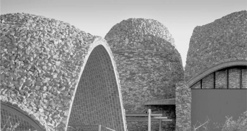
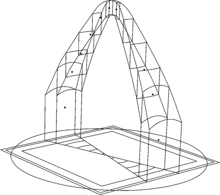
Despite these advantages, earthen arches, vaults and domes present unique challenges to the designer and builder alike. Designers must accept the limitations inherent to the material, including relatively low strengths and susceptibility to weathering. In addition, the methods used to design structurally efficient geometries for arches, domes and vaults are largely unknown in the contemporary structural engineering community, and most building codes do not include earthen vaults as a viable structural system. Proper detailing is absolutely essential to the longevity of earthen structures, as small incursions of water can have disastrous effects on earthen masonry. Finally, working with earthen masonry can be a challenging experience for builders who are accustomed to highly predictable standardized materials. Despite these limitations, earthen masonry arches, domes and vaults can be used to produce sustainable and dramatic structure and spaces, as shown in Fig. 17.1.
17.2 Structural theory for arches, vaults and domes
The structural design of earthen masonry arches, vaults and domes requires a different approach than is used for conventional framed structures. Structural engineering practice has generally focused on three main structural criteria: strength, stiffness and stability (Heyman, 1995). A building must support the applied loads without exceeding the strength of the material, it must not deflect more than established acceptable limits and the structure as a whole must be stable under all expected loading conditions. Although these criteria also apply to masonry structures, only the third criterion, stability, plays a central role in the design of earth masonry structures.
Due to the high self-weight and low compressive stresses, unreinforced masonry vaults are typically a problem of stability rather than strength. The compressive strength of unreinforced masonry is generally far stronger than the loads placed on it, and the tensile strength can conservatively be considered as zero. Unbaked bricks routinely achieve 5 mPa in compressive strength, which would allow a hypothetical tower to be constructed roughly 200 m-high in earth before the bricks at the bottom begin to crush. Applying a safety factor of 10 against crushing would allow for 20 m-high earthen walls. Thus the compressive strength of earth is likely to be at least an order of magnitude more than is required by most structures. Conversely, the tensile strength can be assumed to be zero because earthen bricks and mortar have virtually no resistance to tensile forces. Stiffness is rarely an issue in masonry structures, because the low stresses account for very small displacements due to elastic deformation of the material. While strength and stiffness are of negligible importance in the design of masonry structures, the third criteria, stability, is of paramount importance. In particular, foundation movements or seismic activity can lead to instability of unreinforced masonry. In general, it is not advisable to build earthen vaults in seismic regions.
Instability can best be understood in geometrical terms: if the proportions of an arch, vault or dome are correct, the internal compressive forces will be maintained within the masonry, with relatively low compressive stresses (stress is defined as force per unit area). The task of the designer of an unreinforced masonry structure, whether of stone, fired brick or earth, is to find a shape for it such that the structure will remain in compression under all foreseeable loading conditions.
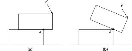
Take, for example, the simple two block structure shown in Fig. 17.2. The load P necessary for collapse is clearly a question of stability, not stress. Of course stress plays a role when the entire load is focused at point A at collapse (Fig. 17.2b), but in most cases of historical masonry construction, the working stress is two orders of magnitude below the compressive strength. The potential cause of collapse is therefore far more likely to be the instability of the structure rather than insufficient compressive strength. This simple example illustrates the value and necessity of stability analysis for unreinforced masonry structures.
17.2.1 Elastic versus plastic design understanding
Conventional methods of structural analysis, known as linear elastic analysis, are not capable of predicting the load, P, which will cause the overturning of a masonry block. Therefore, identifying a proper shape for masonry presents a problem for conventional elastic design techniques. These techniques are effective for determining local stresses in building elements such as steel frames, but do not offer a reliable picture of the overall flow of forces in a structure across a range of support conditions. By idealizing the material as linear elastic, any elastic calculation will incorrectly predict tensile stresses that the material is not capable of supporting. According to an elastic analysis, typically performed using the finite element method (FEM), a masonry arch could not support its self-weight without incurring tensile stresses that would crack the arch. Thus, according to elastic analysis, a Roman stone arch bridge can be declared unsafe due to insufficient tensile strength, despite the fact that it has been standing for 2000 years. Furthermore, an elastic analysis will predict high tensile stress concentrations in some locations, such as the corners of a window in a brick wall. Conventional linear elastic methods are incapable of predicting the actual behavior or the failure state of a masonry vault and are not useful for determining a good form for the structure.
In contrast to elastic design techniques, the plastic design approach, typically called limit analysis or the ‘equilibrium approach’, allows for the existence of many possible load paths within a structure. Rather than attempting to calculate the stresses in a structure in an overly idealized perfect elastic continuum, the safe theorem of plastic design dictates that if one equilibrium state can be found for a structure given a set of loads, the structure can be demonstrated to be safe. There are many different methods of carrying out an equilibrium analysis. Of these, graphic statics is the fastest and most intuitive method for designing masonry vaulting. The graphical method relies on thrust lines to represent the paths of resultants of compressive force flowing through the structure (Ochsendorf and Block, 2009).
17.2.2 Robert Hooke’s ‘hanging chain’
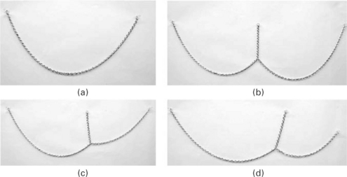
English scientist Robert Hooke (1635–1703) identified ‘the true Mathematical and Mechanical form of all manner of Arches for Building,’ which he summarized with the phrase: ‘As hangs the flexible line, so but inverted will stand the rigid arch’. A hanging chain, which forms a catenary in tension under its own weight, can be inverted to find the ideal form of an arch, which stands in compression (Fig. 17.3). Both the hanging chain and the arch must be in equilibrium, though the chain can only work in tension and the arch can only work in compression. More generally, the shape that a string or chain takes under a set of loads, if inverted, is an ideal shape for an arched structure to support the same set of loads. This simple idea, sometimes called a funicular form, produces a line of thrust that can be used to design and analyze vaulted structures in earthen masonry.
17.3 (a) Hooke’s hanging chain in tension with the corresponding inverted arch in compression; (b) the safety of the cracked dome of St Peter’s in Rome demonstrated by Hooke’s principle.
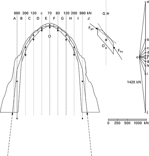
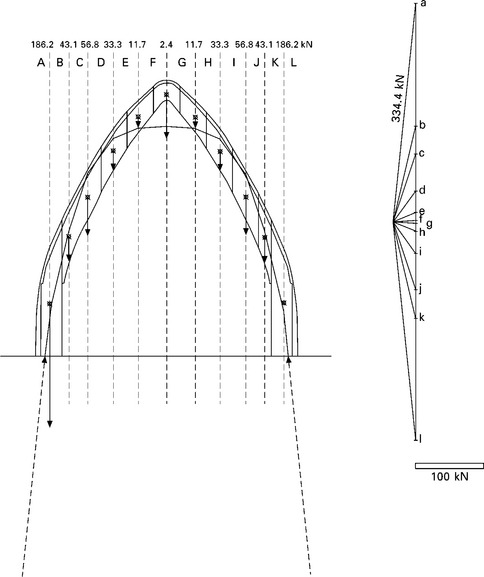
To apply the idea of a hanging chain to an actual masonry structure, consider the semi-circular stone arch shown in Fig. 17.4a. Each voussoir, or stone, in the arch has a known mass and centroid. Because masonry can resist only compressive forces and is very weak in tension, the arch can stand only if a path of compressive forces is shown to lie entirely within the masonry. A model of the arch could be constructed with a piece of string supporting masses that correspond to the weight of each block, and the resulting shape of the string would be the path of the tensile forces necessary to support these weights. By pulling on the ends of the string with different values of horizontal force, an infinite number of equilibrium solutions can be found for the same loading condition. By inverting this string, it can be used to calculate the line of compressive forces lying within the masonry. Though builders in the past have sometimes used physical models made of weights on hanging strings to derive the form of masonry arches and vaults, the same solution can be found using graphic statics as shown by the force polygon (Fig. 17.4b). More detail on graphic statics and how it can be used to calculate the form and forces of masonry structures can be found in the book by Allen and Zalewski (2009).
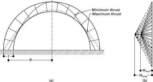
17.4 (a) Minimum and maximum horizontal thrust values in a semicircular masonry arch; (b) the force polygons corresponding to the lines of minimum and maximum thrust for this arch according to graphic statics (image: Katherine Hriczo).
Equilibrium in a masonry arch is visualized by means of a line of thrust, a theoretical line that represents the path of the compressive forces through the structure. If the thrust line strays outside the section, compressive forces must travel through the air, which is only possible if the material can resist tension. The stone arch of Fig. 17.4a has an infinite number of possible thrust lines that lie within the masonry, though only the minimum and maximum values of horizontal thrust are illustrated. The masonry arch is statically indeterminate, with an infinite number of solutions between the minimum and maximum values. In short, multiple equilibrium solutions are possible, with each solution corresponding to a different compressive line of thrust inside the masonry.
The geometry of the arch determines the minimum and maximum horizontal force that is possible within the arch. To assess the safety of a historical arch, a range of possible thrust values can be determined, though the exact internal value of force depends on the exact support conditions, which are known only to the arch. If support movements occur, then the arch will adjust to these movements by forming hinges. Such hinges make the arch statically determinate because a single thrust line can be found that passes through the hinges. A small outward movement of the supports will lead to the state of minimum thrust and a small inward movement of the arch supports will lead to the state of maximum thrust. The minimum (or passive) thrust state represents the least amount the arch can push horizontally on its neighboring elements, as a function of its self-weight and shape. The maximum (or active) state of thrust represents the largest possible horizontal force that this arch can provide. Vaulted masonry structures must bring their applied loads safely to earth within the fabric of the masonry. A more general example of a random stone arch and one possible compressive line of thrust as calculated by graphic statics is demonstrated in Fig. 17.5.
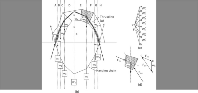
17.5 Random arch with (a) possible internal line of thrust; (b) its inverse, a hanging string with weights proportional to the weights of the voussoirs; (c) the corresponding funicular polygon; (d) one of the arch voussoirs with the resultant forces on it and a closed triangle visualizing the equilibrium of forces in it (image: Philippe Block).
Each individual portion of the arch is held in place by the compressive forces applied to it from adjacent portions. In this manner, the weight of each segment of the arch is carried down to the supports in compression. The equilibrium of a single block in the arch is represented by the bold triangle shown in the funicular polygon of Fig. 17.5c. Because the load accumulates from the center of an arch down, the keystone at the center of the arch supports lower forces than the blocks nearer the base.
17.2.3 Funicular versus geometrical design in masonry
Masonry structures may follow traditional geometry or more structural geometry. Classical geometry is composed of vertical columns and walls, which support arches, vaults and domes that are circular arcs of constant radius. Funicular geometry is defined by the path of forces through structures. Classical geometries are easier to lay out and build, but they use more material because the forms are determined by geometry rather than lines of thrust. In contrast, funicular geometries place material nearest the dominant thrust line, which is the path of forces taken due to self-weight only for most masonry structures. Funicular geometries use less material, but are more difficult to define and construct than classical arches.
17.2.4 Hanging models
Many designers have used hanging models to derive the form of funicular structures, by inverting the geometry found from using weights on strings, or sections of bare chain (Fig. 17.6). Uniform loads can approximate the form of an ideal funicular structure due to dead load, and additional weights can be added to account for other load cases, or to define a larger envelope for the masonry structure. Because masonry cannot resist tension, the designer must create a form that can contain the complete envelope of compressive thrust lines for all expected loadings, including live loads caused by wind, snow and other sources. A chain model allows for rapid exploration of the infinite possibilities of structural form and gives insight into the importance of the support conditions. Such physical models are particularly powerful during initial design explorations. More precise graphical methods can be used to refine the design during later stages.
17.3 Earth masonry arches
The arch is the fundamental structural form for spanning in unreinforced masonry. Even the simple two-dimensional arch has many possible variations, and these can be combined to create countless other structural shapes. The structural action of complex vaults and domes can be understood by analyzing them as a series of two-dimensional arches contained within these shapes. When analyzed this way, the additional structural integrity resulting from the three-dimensional aspect of vaults and domes provides a further margin of safety.
17.3.1 Historic case study: Taq-I Kisra arch
The arch of Ctesiphon is the surviving portion of a barrel vault that originally enclosed the Iwan-i-Khosrau, the throne room commissioned by Khosrau I, ruler of the Sassanid Empire, around 540 AD located in the ancient city of Ctesiphon in modern-day Iraq. (Fig. 17.7). During construction, the horizontal courses of bricks above the imposts were progressively corbelled inwards so that the two walls approached each other at slight curves, which reduced the large area that had to be vaulted (scarre, 1999). The remaining portion of the vault was then constructed against the rear wall using a method of pitched brick vaulting to avoid centering, which was especially advantageous in Mesopotamia where wood was scarce (Heywood, 1919). The vault was constructed with fired clay bricks adhered to one another with gypsum mortar. Gypsum mortar was ideal because it was quick setting and gypsum deposits were locally available (Pope, 1977). In the 1500 years that following its completion, part of the vault collapsed, leaving behind a monumental ruin. The arch of Taq-I Kisra is one of the most impressive masonry buildings in the world today.
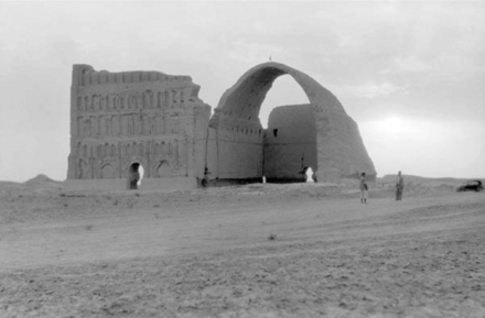
17.7 Taq-I Kisra arch from 540 AD, as photographed in 1932, Ctesiphon, Iraq (photo: Photo Department of American Colony, Jerusalem).
The surviving arch measures approximately 35 m high at its crown, 25 m wide from the spring points and 50 m long. The arch is approximately 7 m thick at its base, diminishing in thickness to approximately 1 m at the crown of vault. The dimensions of the burnt bricks are approximately 30 × 30 × 7.5 cm thick. The Ctesiphon vault was constructed as an extruded series of arches, and it can therefore be considered to act structurally by dividing it into two-dimensional arches.
17.3.2 Structural analysis of Taq-I Kisra arch
A simple thrust line analysis of the arch of Taq-I Kisra can be used to estimate the magnitude of the internal compressive forces and to demonstrate its safety (Fig. 17.8). The forces are considered for a 1-m-wide strip of the arch, which is divided into segments whose weight and centroid must be found by multiplying the volume of masonry by the density of the material (typically around 2000 kg/m3). A possible equilibrium solution for the arch is determined from trial and error using graphic statics, and the resulting thrust line is transferred to the ground entirely within the masonry. Of particular interest for estimating the stability of the remaining arch is the location at which the thrust line falls within the base of the supporting wall. This analysis demonstrates that the arch is well-equilibrated, with the resultant force of roughly 145 metric tons falling within the middle-third of the wall at the base.
17.4 Earth masonry vaults
Though the arch had been used in Egypt much earlier, master builders of the Roman empire expanded the use of the arch in architecture to create a wide range of barrel vaults and domes. Drawing on the roman tradition, builders in medieval europe created simple vaulted churches by using cylindrical barrel vaults, eventually employing pointed vaults to increase interior heights. Gothic builders created increasingly complex arrangements of arches and vaults, using less material than Romanesque barrel vaults. In the Islamic world, master masons used remarkable combinations of arches vaults and domes to invent new spatial possibilities. These historical precedents can serve as inspiration for future designs.
17.4.1 Equilibrium analysis of vaults using thrust lines
To determine possible equilibrium states for a masonry vault, we may divide the vault into a series of intersecting arches (Fig. 17.9). Most vaults can be divided into an infinite arrangement of different arches, though it makes most sense to use symmetry in dividing up a vault. A quadripartite vault, defined by masonry ribs across its diagonals, may be divided into parallel arches that span between the ribs. The ribs then collect the forces to the support at each corner, where the thrust of the vault must be resisted by an adjacent vault or by a buttress. In this way it is possible to estimate the forces in a range of vault geometries, with or without ribs.
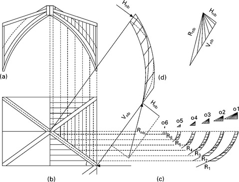
17.9 Graphical analysis of the forces in a ribbed quadripartite vault (a) cross section; (b) plan view; (c) arch sections span between the main ribs; and (d) the rib profile with a safe thrust line and its corresponding force polygon. The loads on the main rib come from the resultants of the series of web arches (image: Philippe Block).
17.4.2 Historic case study: Guastavino vaulting, ca. 1900
Rafael Guastavino Jr (1872–1950) used graphic statics to design and analyze numerous thin shell masonry domes, bringing a historical Mediterranean construction method into 20th-century American buildings (Ochsendorf, 2010). Such equilibrium calculations can help to define the form of the dome, or even suggest locations for flying buttresses, as proposed for the church of St. Francis de Sales in Philadelphia (Fig. 17.10). Their load-bearing domes spanned long distances with minimal material, by making good use of efficient structural forms. In addition, decorative tile finishes and openings for natural light, as in the Elephant House of the Bronx Zoo, add to the visual impact of Guastavino vaults (Fig. 17.11).
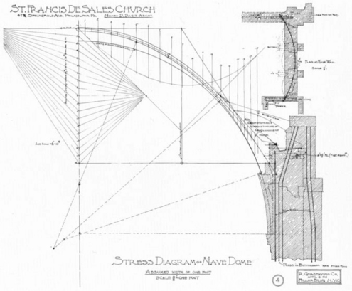
17.10 Graphic analysis for St. Francis de Sales Church Dome by the Guastavino Company, Philadelphia, 1908 (image: Guastavino/ Collins Collection).
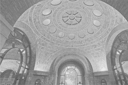
17.11 Inner dome of the Elephant House in the Bronx Zoo, 1909, with numerous openings for natural light Avery Library; photo by Michael Freeman.
Guastavino vaults are strong in compression and weak in tension, and therefore behave similarly to other masonry vaults. By using doubly curving shells in masonry, Guastavino vaults have numerous load paths, giving rise to their legendary strength. Of the more than 10,000 vaults constructed in approximately 1000 buildings throughout North America between 1881 and 1962, no Guastavino vault has ever failed in service.
17.4.3 Contemporary design case study: Mapungubwe Interpretation Center
The Mapungubwe Interpretation Center (Fig. 17.12) was commissioned by South African National Parks to provide an interpretive center devoted to the Mapungubwe culture in Southern Africa. The unique design was a collaboration between Peter Rich Architects and vault designers John Ochsendorf and Michael Ramage. James Bellamy led the construction team and trained local workers to build vaults. The structurally efficient earthen vaults were designed using equilibrium methods to act in compression, with no internal steel for reinforcing. The thin bricks were made from cement-stabilized soil, and the vaults were constructed by training minimally skilled workers to build in the 700-year-old method of Mediterranean tile vaulting. Training workers in the method addressed budget, time and materials constraints while providing jobs for unemployed workers in the region. By using fast-setting mortar to build the first layer of masonry, the vaults were constructed with minimal formwork. The result is an elegant building that is economically, socially and environmentally sustainable.
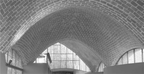
17.12 Vaulted interior at Mapungubwe Interpretation Center, Limpopo, South Africa, Peter Rich Architects 2009 (photo: Robert Rich).
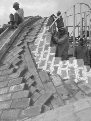
The construction process consisted of making tiles, constructing work guides and laying tile. Stabilized earthen tiles measuring 140 × 290 × 20 mm were fabricated from local soil by modifying a standard Hydraform block press to produce thin tiles instead of blocks. Locally trained masons constructed the vaults following the traditional layered tile technique, laying tiles with their thin edges joined by fast-setting gypsum mortar (Fig. 17.13). Two edges of the tile are in contact with mortar, giving enough purchase to support the tile in a matter of seconds as the gypsum plaster sets. The technique allows masons to construct the vaults with minimal formwork, which reduces the amount of material and increases the speed of construction. After the first layer of tiles is installed, masons increase the thickness of the vault by adding successive layers of tiles interspersed with Portland cement mortar until the entire construction is three to four tiles thick. To be stable during construction, it is essential for each section of the vault to contain compressive arches within the thickness. The completed vaults are capable of impressive spans, with a large vault spanning 21 m, and other vaults spanning 14.5 m. The vaults are designed to ensure that all forces in the structure act only in compression, minimizing the need for steel reinforcement, which is expensive and energy intensive. The Mapungubwe Interpretation Center revives a centuries-old technique in tile vaulting with local materials and labor, with dramatic reductions in embodied energy due to the use of minimally processed soil bricks. Among other international design awards, this building was named the ‘World Building of the Year’ at the 2009 World Architecture Festival in Barcelona.
17.4.4 Contemporary design case study: Start Festival Vault
The Start Festival Earth Pavilion was a temporary earthen structure built in the gardens of Clarence House, the London home of HRH Prince Charles (Fig. 17.14). The pavilion was constructed for Start, a national initiative created by HRH Prince Charles’ Charities Foundation to promote and celebrate sustainable living. Architects Peter Rich and Tim Hall worked with vault designer Michael Ramage to design the structure, which was sponsored by The Earth Awards to demonstrate sustainable building techniques. Mason Sarah Pennal led the construction team.
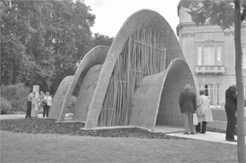
Like the Mapungubwe Visitor Center, the Start Festival Earth Pavilion was constructed of earthen tiles created from local materials. The builder used a modified Hydraform manual press to create the tiles from a mix design consisting of 90% east London soil combined with 10% cement and a small amount of sand. The tiles, which were approximately 20 mm thick, were assembled over a lightweight plywood formwork after curing for a minimum of four days. The total assembly was 60 mm thick, which included two layers of tile and a mortar layer between them in which a nylon triaxial geotextile was embedded to help resist any tensile forces. The temporary foundation for the project was constructed of plywood, and in keeping with the theme of sustainability, the floor consisted of salvaged plywood planks, which were previously used for pressing the tiles. The screen between the vaults was chestnut, harvested a day before it was installed.
The area covered by the vault is approximately 75 m2, which results in a usable floor area of approximately 40 m2. The structure was built in ten days using fast-setting gypsum mortar and earthen tiles. Because of the short duration of the festival, no waterproofing was used on the structure, which instead relied on effective detailing to shed water. The vaults of the start Festival Earth Pavilion were designed to have low stresses throughout the structure. Vertical forces were distributed through large areas of masonry while the horizontal thrust was minimized by making the vault nearly vertical at the foundations. The resulting design develops a maximum stress of only 0.1 MPa, ensuring that the compressive strength of the bricks, which was greater than 5 MPa, was 50 times greater than the highest compressive stress in the structure.
The unique form of the vault presented challenges in design and construction. The parabolic shape of the latitudinal axis was designed according to the flow of forces of the vault, but the longitudinal curve was chosen largely for its architectural appeal. Although the compound curvature of the vault develops considerable stiffness, the saddle shape resulted in tensile forces that required the addition of a geotextile between tile layers to ensure that safe envelope of thrust lines was sufficient. The geotextile also provided tensile strength to withstand asymmetric wind loads, effectively allowing the thrust lines to pass outside of the masonry if necessary.
17.4.5 Contemporary design case study: Freeform Thin-tile Vault
This freeform unreinforced masonry vaulting prototype was designed and built by the BLOCK Research Group at the swiss Federal Institute of Technology (ETH) in Zurich, switzerland (Fig. 17.15). Although the experimental vault was constructed with commercially available fired masonry tiles, the method of design used to find the compressive form and the manner of construction pertain to earthen vaults. The undulating form was designed using Thrust Network Analysis (TNA) – a novel computational form finding approach for exploring compressive form in three dimensions. The resulting freeform shells presented new challenges in tiling patterns, sequence of building and especially the guidework. A complex vaulted structure is capable of generating local forces that are significantly higher than those occurring in the final structure. Temporary means of support must be found to manage these forces to ensure that the partially completed structure does not collapse during construction. The BLOCK Research Group developed a continuous expandable cardboard guidework system using CAD-CAM (computer-aided design and computer-aided manufacturing) cutting and gluing processes to ensure structural stability of the vault during construction (Fig. 17.16).
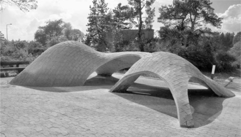
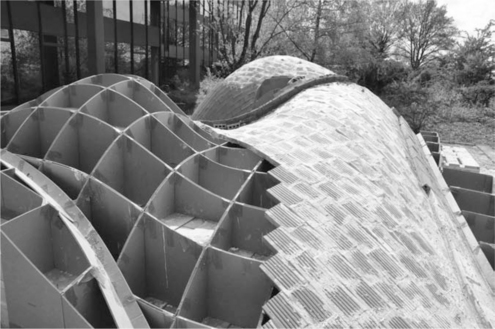
The thin shell prototype was designed by Matthias Rippmann, Lara Davis and Philippe Block and constructed over a period of six weeks by Lara Davis. The custom CAD-CAM guidework was fabricated by Tom Pawlofsky, and the project was sponsored by ZZ Wancor AG and Rigips.
17.4.6 Pitched brick vaults
In contrast to vaults employing double curvature, the pitched-brick vault, sometimes called the ‘Nubian vault’, is an extruded arch whose simplicity of construction offers great appeal. While a typical barrel vault requires formwork, or centering, during construction, the pitched brick vault requires no support from below. When constructing such a vault, masons build one permanent end gable wall with brick to brace the subsequent construction. The bricks are laid in a roughly parabolic shape at an angle of approximately 20° to perpendicular along the longitudinal axis of the vault. This angle allows prior courses of masonry to support successive courses such that no centering is required (Fig. 17.17). Once the vault is complete, buttresses are sometimes formed by raising the side walls by 8 to 10 courses of bricks and filling in the volume between the buttress and vault with plain earth to provide resistance against the horizontal forces, though this is only effective if the supporting walls are buttressed as well. The first examples using this efficient construction technique date back at least 3500 years.
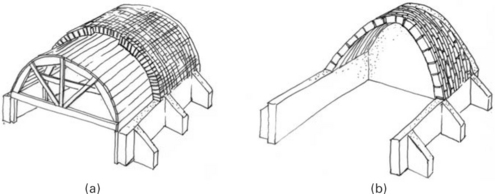
17.17 Vaults under construction (a) Typical barrel vault with centering; and (b) pitched brick vault (drawing: Joseph Dahmen after Edward Allen).
Several organizations have been established to train masons in pitched brick vaulting techniques to address low income housing. The Association La Voûte Nubienne (AVN) in France applies the traditional Nubian vault technique to produce contemporary earth buildings throughout Africa. AVN trains local masons to build the vaults with sun-dried adobe bricks created on-site or nearby, creating dwellings whose thermal mass is well-adapted to the harsh climate. The Nubian technique is especially well-suited for this application: construction is straightforward and does not require wood centering, which is a precious resource. The finished structures do not require metal roofing, which can be expensive in developing countries.
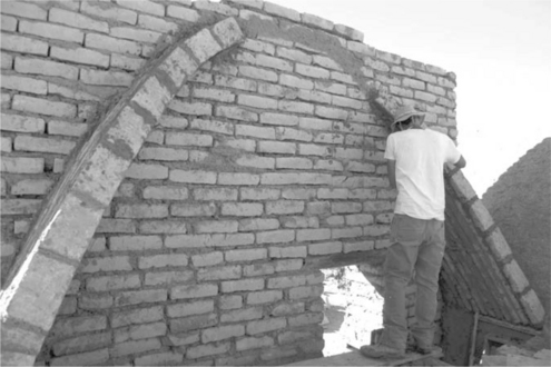
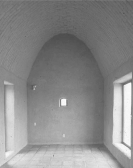
The Adobe Alliance in Presidio, Texas, along the border between the United States and Mexico, was established by Simone Swan to preserve and continue the rich tradition of building with sun-baked adobe bricks. Swan founded the organization after apprenticing with her mentor Hassan Fathy (1900–1989), a noted Egyptian architect who worked to re-establish the use of earthen vaults in Egypt during the 1940s (Steele, 1997). With the help of local masons, Swan creates earthen homes on both sides of the border (Fig. 17.18). The Adobe Alliance teaches the design and construction of handmade adobe vaults and domes built without centering. The vaults and domes are created with hand-molded earthen adobe blocks without the addition of cement-stabilizing materials (Fig. 17.19). Completed vaults are covered in an earthen plaster composed of clay, sand, water, nopal juice, horse manure, lime and finely chopped wheat straw. The natural materials breathe, regulating interior humidity while moderating the harsh temperatures characteristic of the desert climate by absorbing heat in the daytime and radiating it at night. Outdoor courtyards create pleasant micro-climates that provide additional living space. The Adobe Alliance has trained many masons in pitched brick vaulting methods and is building several adobe houses each year.
17.5 Earth masonry domes
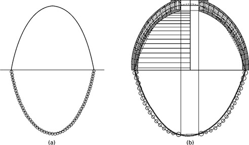
Masonry domes have created some of the most grandiose spaces ever conceived. Masonry domes can be designed and analyzed by dividing the dome into a series of wedge-shaped arches that lean against each other along radial lines (Fig. 17.20a). This is a safe but overly conservative approach, because it ignores the circumferential hoop forces which can develop in a dome (Figure 17.20b). For a hemispherical dome, the hoop forces act in compression in the upper portion, and then change to tension below an angle of approximately 52° from the vertical, which may sometimes require the addition of tension reinforcement near the base of a dome. Wolfe (1921) analyzed masonry domes graphically for a range of hypotheses (Fig. 17.21).
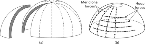
17.20 Idealization of masonry domes (a) considered as series of independent wedges that lean on each; and (b) Combination of meridional (arching) and hoop forces (image: Wanda Lau).
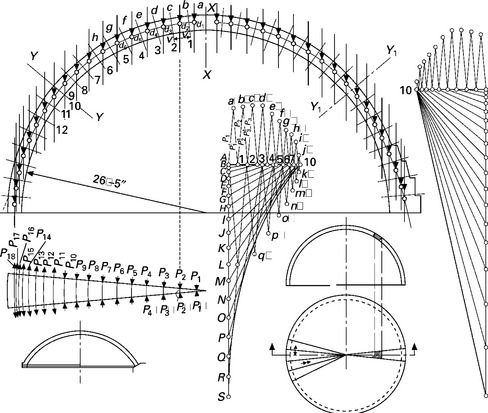
17.21 Graphical analysis of a masonry dome source: Wolfe, 1921.
A two-dimensional arch will collapse if any voussoir is removed, since there would be no other path in compression within the structure. Because of their double curvature, domes allow for many additional load paths in three dimensions (Lau, 2006). Small rounded openings can be introduced in almost any location, provided that compressive forces can flow around the opening. A horizontal circular hole at the top of a dome, creates an opening known as an oculus, which can allow for natural light and natural ventilation. Forces can flow around the oculus in a compression ring, and multiple openings can be made in a dome, as in the case of the Bronx Zoo building by the Guastavino Company (Fig. 17.11). The Pantheon in Rome, whose dome was cast in unreinforced concrete and thus acts as an unreinforced masonry dome, contains an 8.3 m oculus at the center of its 43-m span.
17.5.1 Historic case study: Syrian ‘beehive’ houses, ca. 1700
The semi-nomadic people of northern Syria have constructed corbelled dome dwellings of unbaked earth bricks since the 1700 s (Fig. 17.22) (Mecca and Dipasquale, 2009).
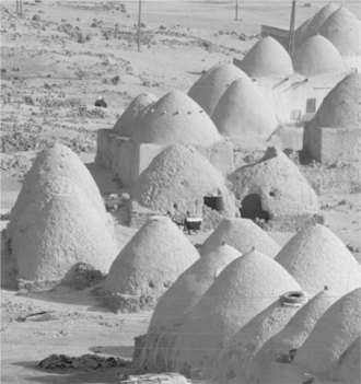
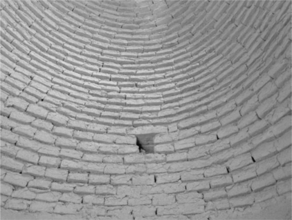
After outlining the square perimeter of the house on the ground, the mason excavates the earth until a solid layer of soil is encountered on which to construct a foundation wall of local stone 60–85 cm thick. The mason then constructs a stone wall stabilized by small stones used as wedges. The dome is created by laying bricks in a continuous helicoidal spiral (built without centering) and is blocked at the top (Fig. 17.23). The construction method results in the trademark ‘beehive’ shape, which appears more like a cone than a traditional dome. Because the structure shifts from a square stone foundation to a circular dome, it can be challenging to bring the dome forces down to the supports. The fragile nature of the unbaked earthen bricks makes the beehive dwellings susceptible to damage due to weathering, and they are often plastered with mud-straw mortar to provide some measure of protection from the elements. The beehive houses require frequent maintenance due to erosion.
The square base of these dwellings varies from 3–3.5 m with heights generally between 4 and 6 m. Larger structures known as ‘Sultan Domes’ have bases that measure as large as 4.5 m with heights similar to the smaller structures. The dimensions of the unbaked bricks formed from local soils vary from village to village.
17.5.2 Structural analysis of typical Syrian ‘beehive’ house
The beehive dome can be approximated initially as a series of arches leaning against each other (Fig. 17.24), though for some geometries, this simplification will not allow for the thrust line to be contained within the dome (Fig. 17.25). Domes gain greater stability from the three-dimensional flow of forces and, in particular, from compressive hoop forces, which prevent the dome from falling inward under dead load. The effect of hoop forces is most pronounced in the upper region of a dome, where circular compression rings maintain equilibrium. This gives a resultant reaction on the meridional, or arching forces, which can deviate the thrust line to keep it within the section of the dome. Many different geometries are possible for domes, provided that compressive hoop forces are capable of developing to assist the arching action.
17.5.3 Contemporary design case study: dome of the Dhyanalinga Meditation Shrine, India
The Temple of the Dhyanalinga, located in the foothills of the Velliangiri Mountains of Southern India, was commissioned to provide a space for meditation (Fig. 17.26). The temple dome was constructed in eight weeks by 300 local unskilled laborers and volunteers. The dome is constructed of fired clay bricks that vary considerably in size because they were supplied by approximately 20 different kilns due to the large numbers required. Because no reinforcement was used anywhere in the dome construction, the engineers who designed the structure had to ensure that only compressive forces acted on it. The completed dome which is elliptical in cross-section, measures 10.1 m high and 23.2 m in diameter. The thickness of the dome is 50 cm at the base, which tapers to 20 cm at the crown, roughly the thickness of a single brick. The dome exterior is parged with cement mortar to provide a weather-resistant finish.
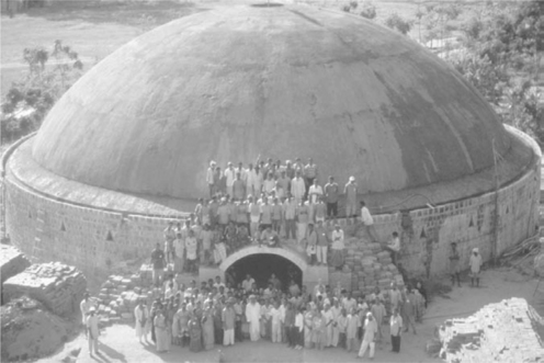
17.26 Dhyanalinga Meditation Shrine, India, 1999 (photo: Auroville Earth Institute).
The dome rests on a foundation of granite rubble masonry set in lime mortar that measures roughly 3 × 3 m. The first course of the segmental dome is laid at an angle of 13° to the horizontal, increasing to 82° to the horizontal at the last course. As the dome was rising, the specification of mud mortar stabilized with lime and sand was adapted by adding more soil to achieve the ideal adhesion based on the angle of the brick layers. To give the mortar its strength and fast-setting properties, 13% cement and 19% lime were added (Auroville Earth Institute, n.d.). The dome shelters a silent atmosphere conducive to spiritual growth and meditation, and is one of the longest unreinforced masonry spans built in recent years.
17.6 Material properties of earth masonry structure
The case studies above provide a general overview of a range of vaulted masonry designs. A series of historical and contemporary examples, together with structural analysis and construction details, allow the designer of an earthen vault to understand the broad considerations for design. However, it is worthwhile to go into more detail for various other aspects of earthen vault construction.
17.6.1 Bricks
It is not possible to speak of one particular size or shape of earthen brick suitable for earthen masonry arches, vaults and domes because of the different demands of each project and location. Bricks used for vaulting may vary widely, with specific brick geometry dictated by performance demands placed on the individual units by the design of the structure and the characteristics of local soils. Adobe blocks such as those used for pitched brick vaults by the Adobe Alliance typically measure 45 × 60 cm (18 × 24 in), whereas tiles for Guastavino-style vaults often measure a mere 25 mm (1 in) thick, with compressive forces acting along the thin axis of the tile. It is necessary that the geometry of bricks be suited to the construction method, and that design strengths be capable of meeting loading with appropriate safety factors, though axial compressive stresses are generally quite low. For environmental and economic reasons, cement content should be kept to the minimum necessary to meet performance requirements, and local soils should be used wherever possible.
17.6.2 Mix designs
Mix designs governing the composition of soil bricks depend on the specific performance characteristics required by a design. Where clay binders are used, only non-expansive clays should be sourced to avoid problems with expansion and contraction. Soils should be well graded with even distribution of aggregate sizes and an equal proportion of fines to produce tightly packed tiles. Soil for brick making should be screened to ensure that individual particles are limited to 5 mm maximum, though this can be increased to as much as 15 mm in the case of larger bricks. Sample bricks should be load-tested to failure to ensure that they are capable of meeting design loads with an acceptable factor of safety. For environmental reasons the minimum amount of cement should be used that is capable of providing bricks of sufficient strength. Moreover, bricks should be capable of withstanding moisture likely to be encountered during construction and the service life of the building.
17.6.3 Bond patterns
Bond patterns vary according to specific construction techniques and desired appearance, but in general, bond patterns should be staggered to avoid weak lines along mortar joints. Stack bonds should be avoided for the same reason, as they can result in weakness along mortar joints. Vaults are sometimes constructed with tiles laid in herringbone pattern, or in multiple layers, which allows masons to improve the cohesion between bricks. Geotextiles, or other reinforcement, can be embedded between masonry layers to address tensile forces due to asymmetrical loading.
17.6.4 Mortar types and properties
The composition of mortar depends on the strengths required by specific designs for arches, vaults and domes. Furthermore, mortar composition will depend on the mix design used for bricks as the two must interface effectively for durable construction overall. Extreme differences between durability of mortar and brick can accelerate weathering, as will occur in an adobe wall with a Portland cement mortar between bricks. For tile vaults, gypsum plaster offers fast setting for the initial layer of tiles but it must be protected from any precipitation during and after construction. Until the initial layer of tiles is parged with cement mortar, construction should be protected from moisture with appropriate measures. Subsequent layers of tile are laid on the initial layer using cement mortar. A final parging coat of rich cement mortar is applied, preferably covered by a layer of impermeable material to prevent water infiltration.
17.7 Design and construction criteria for earth masonry structures
Arches, vaults and domes are capable of creating spaces that are unique in contemporary architecture. These techniques offer efficient use of resources, requiring few or no additional structural elements. Moreover, the earth masonry can be the final finish, reflecting elements of process and the site in a way that few other materials and techniques can match. Design of earth masonry arches, vaults and domes should abide by the design criteria outlined below to ensure longevity, and safety.
17.7.1 Design criteria
Earthen arches, vaults, and domes should be designed such that tensile forces in the masonry do not occur. Compressive force resultants should remain in the middle third of the masonry at the base of the structure. Masonry joints should be approximately perpendicular to the calculated compressive forces to minimize the risk of sliding wherever possible. Point loads on shells should be avoided to prevent local failures. Safety factors must account for variable soil composition, which can cause considerable variation in individual brick strength. Steel reinforcing should be minimized or eliminated entirely with earth masonry as it is difficult or impossible to attain an effective bond between earth and steel and it can cause significant problems in earthen structures due to corrosion. Generally, metallic reinforcement, such as steel reinforcing bars, is prone to corrosion and will shorten the life of a masonry structure if not protected from oxidation. Moreover, this expensive and energy-intensive material is unnecessary when proper design ensures that forces act only in compression.
Structural elements should be designed to resist loads during the construction process as well as in the finished structure. Because arches, vaults and domes derive their strength from their geometry, individual elements often experience greater loads during construction, when geometry is incomplete, than in the finished structure. Foundations should be adequately sized to resist the often considerable horizontal thrust of earth masonry arches and vaults, in addition to vertical loads. Finally, the finished project must be protected from precipitation and other forms of moisture, which can severely compromise the strength of earthen masonry. Durable waterproof finishes should be specified and proper detailing provided to ensure precipitation is channeled away from structure and provision for site drainage provided. Design should provide isolation from foundations to address rising damp in climates where that is an issue.
Undertaking the design and construction of an earthen vault is a serious matter, and is not an amateur activity. Even for experienced vault builders, it is often a good idea to build a smaller-scale version first, to ensure that the construction principles are sound. Not only should the structure be safe under all expected loading conditions, but it must also be safe during each phase of construction. Building an earthen vault or dome can be dangerous, as a collapsing vault can easily kill a person. Finally, unreinforced masonry vaults are not suitable for seismic regions.
17.7.2 Construction criteria
At the outset of any earthen masonry project, a testing program should be established for materials and assemblies prior to the start of construction. Such a program is best established during the design stage to give a sense of the performance characteristics of bricks made of local soils. Such a program should include testing structural components to failure in the event that new designs or unfamiliar soil types are utilized. In addition, random samples of bricks should be tested to failure throughout the project to ensure variability is within acceptable limits of required design strengths. Where final construction will be exposed to natural elements, weathering blocks should be constructed to gauge the effect of precipitation on actual materials. Geometry of arches, vaults and domes should be checked frequently during construction to ensure that they conform to design specifications as even small variations in geometry can cause drastic variation in the structural behavior. This is especially important for unreinforced masonry, which is incapable of withstanding even modest tensile forces. Arches, vaults and domes should be braced as necessary during construction to account for local loading that can be considerably greater under construction than in the finished structure. Finally, projects should be carefully protected from precipitation and other forms of moisture during construction, unless design calls for the project to be exposed to the weather and material selection has been made accordingly.
17.8 Future trends
Earth masonry has been in use constantly for nearly 10,000 years and is one of the oldest building materials on the planet. Arches, vaults and domes have been employed to enclose space for several millennia. Current interest in these traditional structural shapes and materials is not merely historical, however. They offer the contemporary designer rich possibilities for achieving radical new designs. Future improvements to design tools coupled with an increase in environmentally sustainable building techniques will contribute to the continued relevance, innovation and growth of earthen masonry arches and vaults. Sophisticated software will render masonry design in accordance with flow of forces more intuitive. Computational design tools will extend equilibrium methods to three dimensions, increasing our understanding of forces and allowing for complex forms in the future. As the sophistication of three-dimensional modeling software increases, architects are challenged to find materials capable of realizing non-standard shapes. Double curvature that can be difficult or impossible with many planar materials is possible with traditional earth masonry. Finally, as environmental concerns grow more pressing, using locally sourced materials low in embodied energy to build structurally efficient forms will only increase in popularity. Thousands of years after these materials and methods first appeared, earthen vaults still have untapped potential to create exceptional buildings.
17.9 Acknowledgments
The authors would like to thank Michelle Morales, who assisted with the background research for this chapter as part of the Undergraduate Research Opportunities Program (UROP) at MIT in 2010. Michael Ramage kindly offered details and images of the Start Pavilion. Philippe Block, Lara Davis and Matthias Rippmann provided information and photographs of the vaulted structure by the BLOCK Research Group at the ETH. Simone Swann provided the images for the Adobe Alliance.
17.10. Sources of further information
Heyman, J.The Stone Skeleton: Structural Engineering of Masonry Architecture. Cambridge: Cambridge University Press, 1995.
Heyman, J.The Masonry Arch. Chichester: Ellis Horwood, 1982.
Huerta, S.Arcos, bóvedas y cúpulas: geometría y equilibrio en el cálculo tradicional de estructuras de fabrica. Madrid: Instituto Juan de Herrera, 2004.
Lancaster, L.Concrete Vaulted Construction in Imperial Rome. Cambridge: Cambridge University Press, 2005.
Mecca, S., Dipasquale, L.Villages of Northern Syria. An Architectural Tradition Shared by East and West. Pisa: Edizioni ETS, 2009.
Ochsendorf, J.Guastavino Vaulting: The Art of Structural Tile. New York: Princeton Architectural Press, 2010.
Sondicker, J.Graphic Statics. Charleston, SC: Bibliolife, 2009.
Steele, J.Architecture for People: the Complete Works of Hassan Fathy. New York: Whitney Library of Design, 1997.
Research group in masonry structures at the Massachusetts Institute of Technology.
Resources on Guastavino tile vault construction.
Thrust Network Analysis developed by the BLOCK Research Group at the Swiss Federal Institute of Technology in Zurich (ETH Zurich).
www.block.arch.ethz.ch/equilibrium/
Web hosted program developed at the BLOCK Research Group explains the behavior of structures and allows users to making their own drawings for their structural analyses and design explorations.
http://acg.media.mit.edu/people/simong/statics/data/
Interactive demonstrations of graphic statics that involve the user in experimentation with the relationship between structural form and forces,
www.designexplorer.net/newscreens/cadenarytool/applet/index.html
3D Hanging chain modeler developed by Axel Kilian.
Simone Swan’s Adobe training workshop in Presidio, Texas.
French/African NGO devoted to training masons to build Nubian vaults.
17.11 References
Allen, E., Zalewski, W.Form and Forces: Designing Efficient Expressive Structures. Hoboken, NJ: Wiley, 2009.
Auroville Earth Institute, ‘Dome of the Dhyanalinga Meditation Shrine’, last accessed 2010, www.earth-auroville.com/maintenance/uploaded_pics/12-dhyanalinga-dome-en.pdf, n.d.
Chaturvedi, S., Ochsendorf, J. Global environmental impacts due to cement and steel. Structural Engineering International. 2004; 14(3):198–200.
Heywood, E. Ctesiphon and the Palace of Khosroes. The Geographical Journal. 1919; 53(2):105–108.
Heyman, J.The Stone Skeleton: Structural Engineering of Masonry Architecture. Cambridge: Cambridge University Press, 1995.
Lau, W., Equilibrium analysis of masonry domes [Master’s Thesis]. Massachusetts Institute of Technology, Cambridge, MA, 2006.
Mecca S., Dipasquale L., eds. Villages of Northern Syria. An Architectural Tradition Shared by East and West. European Institute of Cultural Routes, 2009.
Ochsendorf, J.Guastavino Vaulting: The Art of Structural Tile. New York: Princeton Architectural Press, 2010.
Ochsendorf, J., Block, P. Designing unreinforced masonry. In: Allen E., Zalewski W., eds. Form and Forces: Designing Efficient Expressive Structures. Hoboken, NJ: Wiley, 2009.
Pope, A.U.A Survey of Persian Art Vol II. Tehran: Soroush, 1977.
Scarre, C. The Seventy Wonders of the Ancient World: the Great Monuments and How They Were Built. London: Thames & Hudson, 1999; 185–186.
Steele, J.Architecture for People: the Complete Works of Hassan Fathy. New York: Whitney Library of Design, 1997.
Wolfe, W.Graphical Analysis: a Textbook on Graphic States. New York: McGraw-Hill, 1921.