Structural steel elements within stabilised rammed earth walling
Abstract:
This chapter deals with how structural steel elements can enable stabilised rammed earth (SRE) to be used to greater architectural and structural effect. It includes descriptions of lintel systems, portal frame cladding systems, attaching of steel members to walls and the embedment of structural steel posts within the wall panels. It also describes potential problems of using structural steel within SRE walling.
18.1 Introduction
Modern stabilised rammed earth (SRE) walling may require the inclusion of steel members to resist specific point loads, horizontal span loads and, in some cases, general wind loads. This chapter will provide an overview of how steel is being used to extend the architectural usefulness of modern SRE. The chapter will also provide designers with some measure of warnings about how SRE walls can react to the inclusion of structural steel, and hopefully highlight the best options for various applications. The chapter deals with structural applications that have been used successfully on over 3000 SRE projects predominantly in Australia, South Korea, Thailand, the UK and, most recently, the USA.
We strongly suggest structural designers from countries with specific seismic codes use ideas within this chapter with the understanding that they are considered for seismic applications. See Section 18.7 of this chapter.
18.2 Structural steel for stabilised rammed earth (SRE) walling
in the design of a typical single-storey SRE house the only structural steel required is for the lintels over door and window openings. Vertical steel posts are only needed in the event of a massive point load-bearing on a wall face or at the very end of a wall where there is little mass to resist a given weight. AS a rule 300-or 400-mm-thick SRE or 400-mm-thick insulated stabilised earth (ISE) built with a compressive resistance of 5 pascals (MPa) can withstand common roof loads assuming these loads are spread across wall plates fastened down onto the tops of the walls.
The three variables commonly used by engineers to assess the capability of SRE to withstand loads are:
1. wall thickness – 300 or 400 mm
3. unconfined compressive strength – design to 5 MPa. Increased MPa can be achieved with careful soil blending and increased stabiliser. Site testing of batch samples can further assist an engineer to use SRE to greater structural effect.
The tensile resistance of SRE is normally calculated as 10% of the compressive strength.
18.2.1 Window and door openings
Window and door openings are constructed in situ between two opposing wall panels, or ‘block-outs’ within the confines of larger panels. These ‘over-fill’ sections require lintels, which in most cases can be bolted into the panels on either side or cast over the top of ‘block-out’ openings. For openings 1500 mm or greater, steel tee lintels are used. For smaller openings, layers of horizontal steel bars are used to create solid masonry lintels. For a detailed description of these lintel systems see Section 18.4 of this chapter.
18.2.2 Point loads on wall faces
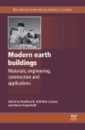
Where a beam needs to be attached to a wall face there are two means of providing an effective contact point:
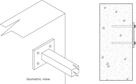
1. For beam loads requiring moderate resistance, the end of the beam can be attached using a plate with fastening holes drilled through it. The plate can be anchored to the wall face using (preferably) chemical anchor bolts embedded two-thirds of the thickness of the wall
2. For beam loads with a serious point load, a steel column can be embedded in the centre of the wall with a cleat attached to fasten the end of the beam to at a later time. For further details on the use of columns, see Section 18.5 of this chapter.
18.2.3 High wall stability
The architectural parameters for SRE are forever pushed to greater heights (literally). The use of embedded steel sections can provide lateral support for walls beyond 6-m heights. The requirement for embedded steel columns or portal frames has been especially prolific where there are few intersecting floor or roof frames to act as bracing, or few intersecting walls to act as buttressing. For more details on embedded steel columns, see Sections 18.5 and 18.5.5 of this chapter.
18.2.4 Cantilevered wall stability
Many modern buildings use SRE as a ‘spine wall’. This wall will dissect the building, often as a corridor or ‘gallery’ with the living areas to the side, which captures winter sun, and the sleeping and utility areas to the other side.
These long walls can provide an excellent structural brace through the guts of the building. In many cases the walls extend beyond the constraints of the building and out into the garden as striking cantilevered elements.
These cantilevered walls may require steel columns within them (see Section 18.5 of this chapter). The engineer will determine wind loads and what resistance is required. As an added stiffener Earth Structures have used inverted 100-mm steel angles with the vertical leg cut into the centre of the wall top and the horizontal face bolted at 600-mm centres onto the wall top. These steel elements can be capped over using folded steel or cast masonry render capping systems.
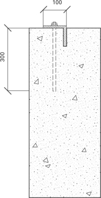
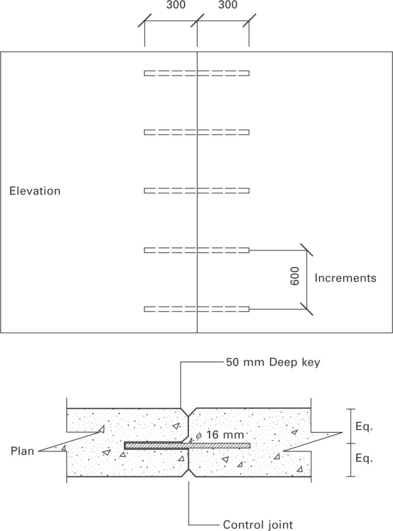
Another precaution for preventing rocking action between SRE cantilevered panels is to cast in horizontal dowels at 600-mm increments between each panel.
18.2.5 Precast walls
The use of precast SRE is becoming increasingly used for two particular applications:
1. to construct sign or entry walls for remote locations
2. to clad SRE buildings where the usual in situ construction methods are not viable.
Precast SRE walls are lifted from a steel tee ‘lintel’ base and can be either transported to site on flat-bed trucks or elevated from a casting site adjacent to the building. For details about pre-cast steel elements see Section 18.6 of this chapter.
18.2.6 Retaining walls
Structural engineers need to be aware that SRE has the capacity to retain ground loads to a certain extent. Successful applications of SRE retaining walls have employed structural systems described in Section 18.6.1 of this chapter.
18.3 Design parameters for using structural steel within stabilised rammed earth (SRE) walling
The purpose of this section is for the author to impart to the reader some of the hard-earned lessons of using steel elements within SRE walling. In many ways it is the most important section of this small chapter.
18.3.1 Shrinkage cracking
The most important factor to consider when designing SRE with embedded steel sections is shrinkage. SRE walls shrink on both the horizontal and vertical axis. By contrast, steel does not shrink, therefore it can be used to restrain shrinking walls. However, these embedded steel sections have the capacity to cause shrinkage cracks.
How to avoid shrinkage cracking:
• Use a mix design that eliminates wall shrinkage. Initial soil testing will determine what the linear shrinkage rate is of the selected material (see Chapter 22, Section 22.4.3, ‘linear shrinkage testing’). If the linear shrinkage is above 2% then add sharp, washed sand to the matrix until a linear shrinkage rate of 1% or less is achieved. For construction using SRE to clad portal frames the linear shrinkage rate should be nil. This is known as a non-plastic material
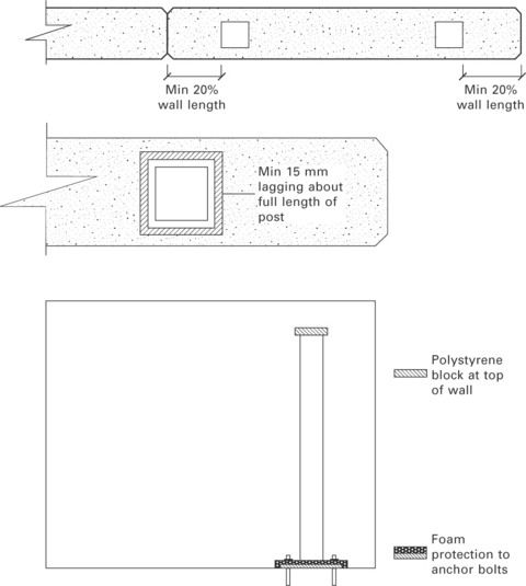
• Ensure all steel sections are placed with a minimum of 20% of the wall length between the embedded steel section and the ends of the wall panels. Thus within a 2500-mm-long panel, ensure the steel post is a minimum of 500 mm from the ends of the wall
• Ensure embedded steel sections are wrapped using closed cell foam to provide some space for the walls to shrink before they meet the resistance of the steel
• Ensure all horizontal gussets, cleats or stiffeners that are welded as attachments to the vertical steel section are covered using low-grade polystyrene with a minimum 25 mm thickness
• Ensure any anchor-bolts at the base of steel columns are wrapped using polystyrene or ‘filler-foam’
• Ensure that the very top of embedded steel posts are clad with a minimum of 25 mm polystyrene. The tops of steel posts are often overlooked as shrinkage-crack points with devastating consequences.
It is important to have adequate cover over embedded steel within SRE walls. Earth Structures Group policy ensures a minimum cover of 100 mm SRE between the steel and the external face of the wall. This applies to the side surface of the wall only. Needless to say the ends of the walls require a minimum 20% of the wall length as cover.
Engineers will determine whether embedded steel will require galvanising. Rusting steel sections within the walls will in time ‘explode’ wall surfaces as the corrosion expands the profile of the steel. The increased embodied energy created by galvanising is normally offset by the extended lifespan of the wall.
18.3.2 Working within the parameters of the SRE formwork
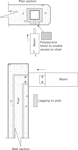
The construction sequence of SRE needs to be taken into account so cast-in steel elements don’t hinder the formwork erection. Much of the skill of good structural design lies in working within the confines of the SRE formwork. Unlike concrete formwork, SRE forms cannot be cut and discarded. The forms are designed to last indefinitely which contributes to the remarkably low embodied energy of the product. An example: a steel post needs to be cast into a wall that will have an intersecting horizontal beam attached. The attached horizontal beam will be an obstruction to the SRE formwork erected on either side of the wall. The engineer allows for a cleat to be welded to the side of the post that protrudes only as far as the inside face of the SRE formwork. All sides of the cleat are clad using 100 mm of polystyrene to enable the beam to be bolted to the post later. The use of ‘extender cleats’ is a common way to overcome the installation of beams and trusses at a later time.
Modern SRE design and construction allows for some degree of movement to occur between each panel. This is called fully articulated design, and it ensures that slight sagging in the concrete footings or raft slab will not be transferred into the fabric of each panel, but rather will be taken up as movement in the control joints between each panel.
Thus, when designing lintel systems it is important not to ‘embed’ lintels from one panel to the next, but rather to allow for adequate shear load resistance that will reduce the likelihood of cracking.
18.4 The use of steel lintels for stabilised rammed earth (SRE) applications
There is no end to how engineers might design steel lintels for SRE applications. Here are the systems we have used for efficient and structurally sound outcomes over the past 30 years.
We avoid the use of timber lintels as even the most seasoned timber will eventually twist with dire consequences.
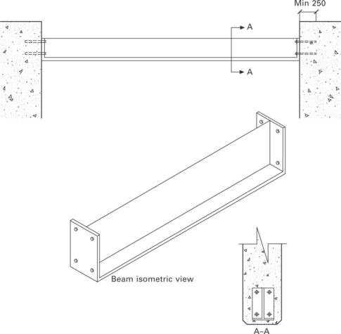
18.4.1 Steel tee lintels – for openings 1500 mm and greater
It is important that the attachment point of the lintels to each opposing wall allows for articulation between each panel (see Section 18.3.2 of this chapter). Thus do not ‘embed’ the lintels in the opposing walls. Rather, use an end plate welded to each end of the tee section with sufficient holes to allow for adequate shear resistance of the bolts embedded in each opposing wall.
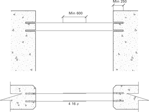
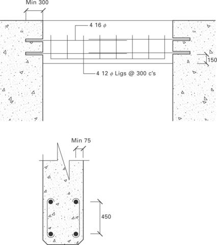
18.4.2 Y bar reinforced masonry lintels – for openings 1500 mm or less
The first row of Y bars need to be one course of SRE above the horizontal soffit. The following courses are normally laid at every second course thereafter. Each course of SRE is normally 150 mm deep. To save time drilling the holes for the Y bars in the opposing wall ends, sections of plastic electrical conduits can be placed and rammed into the wall ends.
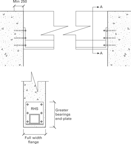
18.4.3 Massive steel lintels – for openings 5000 mm or greater
In the event of the architect requiring a very wide opening, the steel lintels can become massive, and generally require the lintel ends to be mounted at each end on steel posts embedded within the walls at each end. This is problematic as the builder will need to construct customised end shutters to fit around the lintels.
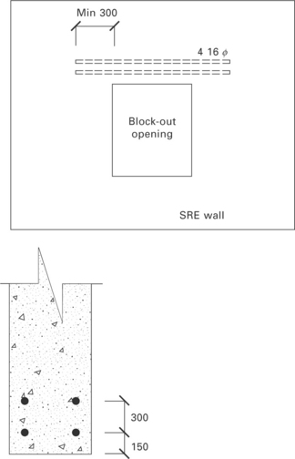
18.4.4 Reinforced masonry lintels for ‘block-out’ openings
At times a smaller opening is required within the envelope of a larger SRE panel. These openings are called ‘block-outs’ as they comprise a shape ‘blocked out’ of the wall using a collapsible timber ‘box’. Reinforcing Y bars are laid in sequence within the SRE above the opening, usually with a 300 mm bearing on either side of the opening.
18.4.5 Header-beam style reinforced masonry lintels – for over-fills 1500 mm or greater
In the case of an architect not wanting to see a steel lintel expressed at the window head, a header-beam system of masonry lintel can be used. This system incorporates vertical ligatures, which are slow to construct and require the use of small-head pneumatic rammers. They should be avoided as they are a cumbersome and expensive option.
18.5 Steel columns embedded within stabilised rammed earth (SRE) walls
When a point load is too great for a bolted end-plate fixture, an engineer may need to pitch the load from a column embedded within the SRE wall. There are three conditions that will ensure the column will not cause problems with the wall.
18.5.1 Column placement
Ensure the column is placed either at the very end of the wall (so one face of the column is flush with the end of the wall) or at least 20% of the total wall length from the end of the wall. Both these precautions will minimise the risk of the wall cracking as a result of the column acting as a resistance to shrinkage.
18.5.2 Cleats and intersecting beams or trusses
Ensure any cleats for beam or truss attachments welded to the column do not extend past the face of the SRE formwork. The cleat can be clad using polystyrene, which can later be stripped out allowing access for attachment of the beam or truss. If the cleat protrudes past the face of the formwork, the SRE contractor has to cut expensive formwork or custom-make forms to fit around the cleat.
18.5.3 Lagging steel columns
Ensure steel columns are lagged using closed cell foam with a minimum thickness of 15 mm. this will allow the steel to expand or contract and will also further minimise the risk of wall shrinkage cracking along the face of the column.
18.5.4 Steel reinforcing bar
As a rule SRE contractors condemn the use of vertical steel reinforcing within walls. SRE shrinks on the vertical plane, while the embedded reinforcing steel acts as a hanger. The result is minor but unsightly cracking along the horizontal form lines.
Vertical steel reinforcing bar also impedes efficient production as it becomes an obvious obstacle for the rammers and for the safe feeding of the walls. Engineers need to make every effort to minimise or exclude the use of vertical reinforcing bar in SRE walls.
18.5.5 Steel portal frames
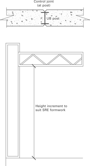
Portal frames can provide a last resort solution for stabilising SRE structures, especially for multi-storey projects. Portal frames create a highly stable structure around which SRE walls can be used as a cladding material. They are an expensive option both economically and in terms of embodied energy. One challenge with designing a portal frame-SRE system is ensuring minimal obstacles for the SRE cladding to be built up to and around the intersecting trusses and beams.
Building SRE up to the base of intersecting steel beams is quick and relatively simple. The vertical posts of the frame can act as props for the walls, which can be a huge advantage. If the beams can then be placed at heights that ‘work’ with SRE formwork increments, the challenge of building around them is significantly reduced. Intersecting beams and trusses need to be placed at large enough spaces to allow elevating machinery such as scissor-lifts to pass between them. The message here is for the structural engineer, architect and SRE contractor to sit down very early in the design process to sort out the beam heights and to imagine the process of efficient SRE production from the word go.
18.6 Structural systems for elevated or ‘precast’ stabilised rammed earth (SRE) panels
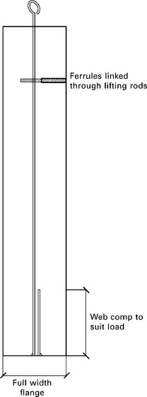
Elevated SRE panels, or ‘precast’ SRE is an increasingly popular method to clad buildings that have difficult or no access for in situ construction. SRE precast requires a different approach to structural design from precast concrete. Precast SRE requires a lifting restraint from the very base of the panel. A simple solution is to build the panel on a steel tee ‘lintel’ with a full-panel-width flange at the base. Two lifting bars are welded to the web of the lintel set one-sixth of the panel length distance in from the end of the panel. The lifting bars need to be sleeved using a plastic conduit to minimise the risk of the SRE shrinking along the length of the steel. A spreader bar is attached to the lifting rods and the panel can be hoisted in place by crane or transported to site on a flat-bed truck prior to placement. Steel ferrules for locating the panel back to a portal frame can be threaded down the lifting rods to allow for greater resistance, thus using the actual lifting rods a load restraint.
18.6.1 Retaining walls
SRE retaining walls require some measure of additional structural resistance for backloads of heavy, wet ground loads.
Wall thickness
SRE retaining walls can be designed using thicker sections to withstand loads. In some cases wall thickness can be staggered to create a tapered structure with the greatest base loads bearing on the thickest sections of the wall.
Footing design
The concrete footings beneath the walls can have extended toe bearing to resist tipping action. These extended footings need to be used in conjunction with steel reinforcement within the SRE wall.
Vertical steel reinforcement
Vertical steel reinforcement bars can be used to restrain loads on SRE retaining walls. Use caution to prevent horizontal cracking of the SRE (see Section 18.5.4 of this chapter). Ensure the steel bars do not exceed one-third of the height of the wall. Also ensure the bars are lagged at the very top of the bar using a polystyrene ‘cap’ so the wall can shrink into the cap rather than creating a resistance point.
Waterproofing and drainage
The most important thing is to drain the ground water away from the retained area to minimise the load on the wall by using slotted drainage pipes and coarse, loose drainage aggregate.
All SRE walls are prone to rising damp. Walls must be thoroughly protected from ground water to a level 75 mm above the surrounding ground level using both painted membranes and plastic geo-fabric membranes.
SRE in conjunction with other masonry support
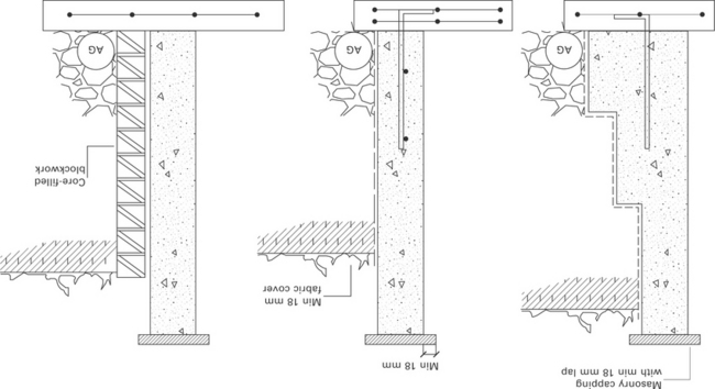
At times a structural or civil engineer will require further support to restrain large retaining loads against an SRE wall. Reinforced core-filled block-work or reinforced ‘shot-crete’ can be used to mitigate the retaining loads against SRE walls. Ensure SRE walls are waterproofed regardless if other masonry elements are employed.
18.7 North American structural steel
North American rammed earth has developed in a very different way from the Australian methodology, which enjoys an entirely non-seismic environment and uses different soil blends. North American rammed earth compressive strength requirements are typically a minimum of 6 MPa compared with the Australian 3.5–5 MPa minimum compressive strength.
Linear shrinkage in the vast majority of North American soil blends is so low as to not be a consideration. The delightful simplicity of rammed earth walls without steel in them at all is something North American earth building contractors dream of. The standard reinforcing in North American rammed earth is one or two mats of 12 mm or 16 mm rebar in a 600 mm grid. Structural steel and rebar mats seldom work well together, either in terms of buildability or with regards to thermal bridging.
Designers of North American rammed earth buildings should use structural steel very cautiously as the combination with rebar mats can create designs that are expensive and difficult to build.
18.8 Conclusion
The use of structural steel, in particular portal frames, has enabled modern SRE to achieve some remarkable architectural outcomes. However, as a contractor it is always preferable to build walls with minimal steel sections – purely from an efficiency point of view, but also knowing the structural capacities of the SRE alone are being used by the architect and engineer to the best of their ability.
Steel contains considerable embodied energy. Given our current environmental challenges, an inevitable shift towards simpler design will require less structural steel within solid masonry walling, including SRE. The challenge for ideal architecture is to minimise the embodied energy created within the building while maximising the structural and life cycle efficiencies of materials such as earth walling.
18.9 Acknowledgements
The author would like to thank the following for their imaginative and courageous help over the years designing workable structural systems for the SRE industry in Australia: Giles Hohnen, Phil Taylor, John Bahoric, Simon Swaney, Brad Overson, Alan Brooks, Bill Smalley, Peter Chancellor, Dale Simpson, John Brock and the many other structural engineers who have had a crack at solving seemingly unsolvable challenges.
18.10 Sources of further information
Little has been written about the structural capacities of contemporary SRE. The following are useful guides to be used in conjunction with the suggestions made within this chapter.
| AS 4100 | Steel Structures Code |
| AS 3700 | Masonry Code |
| AS 3600 | Concrete Code |
CSIRO Bulletin No 5, edition 4 ‘Earth wall construction’. (Note this is a relatively outdated document. The design recommendations are based on an assumption of a maximum bearing resistance for SRE of only 2.5 MPa. Authorised site MPA testing can elevate the engineer from designing walls within this low recommended MPA parameter.)