
Embankments and dams
Abstract:
Based on the purposes and types of construction materials used, embankments and dams are classified into several categories. Emphasis is given to those embankments used for hydropower, irrigation and flood control. These types of embankments are called embankment dams. This chapter gives an overview of the common types of embankment dams, construction materials, construction control, maintenance, failures and causes of failures, analysis and design, and future trends. Moreover, the use of natural fibers as reinforcement for embankments is briefly discussed.
20.1 Introduction
Embankments are among the most ancient forms of civil engineering structures but are still among the most relevant ones. They are widely used, e.g. as embankment dams for reservoirs, as dikes for flood control along river banks and as road, railway and airport runway embankments in transportation. The requirements on performance of embankments depend mainly on their purposes. In hydraulic engineering and flood control, embankments are used to hold water back and for flood control respectively. Therefore, the seepage behavior is of primary importance. In road and railway construction, the settlements, particularly differential settlements of embankments are of major concern. In any case, the stability of embankments must be guaranteed since failure of embankments and dams can have serious consequences.
Embankments may vary significantly in size (height and length). To date the tallest earth dam in the world, the Nurek Dam of Tajikistan in Central Asia, is about 300 m high, while most embankments along river banks and road/railway embankments are only a few meters above ground. Whereas most embankment dams of reservoirs are only several hundred meters long, the river and road/railway embankments can reach lengths of hundreds of kilometres. Despite the striking difference in size and length, however, some basic principles must be observed in design and construction of embankments.
Based on the types of construction materials used, embankments are classified into several categories. These include reinforced embankment, earthfill embankment and rockfill embankment. In this chapter particular attention is given to those embankments which are used for the hydroelectric generation schemes, and irrigation and flood control works. These types of embankments are called embankment dams.
20.2 Types and selection of embankment dams
There are several types of embankment dams. The designs have variability relating to the degree to which seepage within the dam is controlled by provision of filters and drains, the use of free draining rockfill in the embankment, and the control of foundation seepage by grouting, drainage and cutoff construction.
Based on the types of construction materials used, embankment dams are classified into two groups. These are earthfill embankment dams and rockfill embankment dams. The selection of the type of embankment dam to be used at a particular site is affected by many factors. These include availability of construction materials, foundation and/or site conditions, climate, topography and relations to other structures and time of construction. For example, an inclined core can be used when the dam site is located in a high seismic area (Tensay and Wu, 2010). An embankment dam should be designed to satisfy the specific topographic and foundation conditions at the site and to the use of the available construction materials, there are no real standard designs of embankment dams. Hence the embankment dam geometry as well as the type of construction materials varies.
20.2.1 Earthfill embankment dams
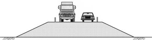
The embankment body fulfills both structural and hydraulic requirement. Depending on the height and hydraulic requirement of the dam, several construction forms are feasible. These include homogeneous embankments (Fig. 20.1), with toe drain (Fig. 20.2), with horizontal drain, with horizontal and vertical drains, and zoned earthfill (heterogeneous) with either central core or inclined core. Homogeneous embankments with small height are usually used as levees along riverbanks and in road and railway construction. Whereas the settlement of embankments is a crucial issue for highways and railways, the slope stability and hydraulic properties (seepage and internal erosion) are of central interest for flood protection.
20.2.2 Rockfill dams
For dams of great height, rockfill material is often used for the dam body. Firstly, fine grain soil is usually not available in the vicinity of the dam site. Secondly, the shear strength of rockfill material is much higher than earthfill. Heavy machines have given rise to better compaction and made the use of very coarse rockfill (boulder diameter of about half a meter) for dam construction feasible. The tallest rockfill in the world is the 233 m Shuibuya Dam in China completed in 2008. The large boulders and the voids among them give rise to very high permeability. In hydraulic engineering (for electricity or irrigation), water loss is important. Therefore, a water barrier must be provided to minimize the water loss. The water barrier can be located either in the dam centre or on the dam surface.
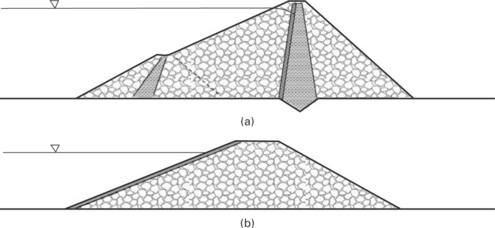
Rockfill dams can be classified into several groups according to the arrangement of the dam sections, e.g. with a centrally located core, with an inclined core (Fig. 20.3a), with bituminous concrete or asphalt facing (Fig. 20.3b). The water barrier of the Shuibuya Dam in China is a concrete face on the water side. A bituminous facing is said to show higher ductility, which is of advantage during earthquakes. The core material could be made of clayey soil, mixed soil or asphalt concrete. Frequently, it is difficult to get fine materials for the core construction. The use of mixed core and to some extent asphalt membrane as a substitute for the fine core materials has become quite common in the construction of embankment dams. The main dam body consists of rockfill material and transition zones for structural resistance, and core and facing zones shall minimize seepage. A filter zone should be provided for a rockfill dam to prevent erosion, i.e. migration of fine soil particles due to seepage force. Often a transition zone consisting of granular soil (gravel and sand) is provided between the dam shell (rockfill) and the dam core (fine grained soil).
20.3 Zoning of embankment dams and construction materials
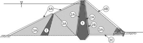
Typical zoning of embankment dams and numbering of these zones is shown in Fig. 20.2. Accordingly the construction materials used for the embankment dam are determined by the function of each zone. The description of the construction materials (Fell et al., 2005), will be provided with reference to these zoning and zone numbers.
(a) Zone 1 is described as core. The function of this zone is to control seepage through the dam. The construction materials used for this zone could be clay, sandy clay, clayey sand, or silty sand. These materials could be used with some gravel. Usually the percentage passing through the 75 m is more than 15%.
(b) Zone 2A is described as fine filter. This prevents erosion of zone 1 and the dam foundation, and prevents build up of pore pressure in the downstream face. Construction materials used are sand or gravelly sand with less than 5% fines passing 75 m. The fines should be non-plastic.
(c) Zone 2B is described as coarse filter. This prevents erosion of zone 2A into rockfill. Moreover, it discharges seeped water. The materials used are gravelly sand or sandy gravel.
(d) Zone 2C is described as upstream filter and filter under riprap. The upstream filter prevents erosion of zone 1 into rockfill upstream of dam core. Where as the filter under riprap prevents erosion of the zone 1 through riprap. The construction materials used include well graded sandy gravel or gravely sand with 100% passing 75 mm but not greater than 8% passing 75 m and the fines must be non-plastic.
(e) Zone 3A is described as earthfill / rockfill. This zone provides the stability, and free drainage to allow discharge of seepage through and under the dam. The construction materials are quarry run rockfill with the oversize removed in quarry or on dam. They are dense, strong, and free draining after compaction. Based on how coarse or fine the rockfill materials are, they are compacted in layers ranging from less than 1 m to 1.5 m with maximum particle size equal to compacted layer thickness.
(f) Zone 4 is described as riprap. The materials used for this zone are selected dense durable rockfill sized to prevent erosion by wave action and sudden draw down.
20.3.1 Design and specification of filters
The basic requirements of filters are that they are sufficiently fine grained to prevent erosion of the soil they are protecting and they are sufficiently permeable to allow drainage of seepage water. These basic requirements are best met by designing the particle size of sand and gravel filters in relation to the particle size of the soil being protected. Criteria developed through many years of experience are used to design filters which will prevent migration of protected soil into the filter. This criterion is based on the grain-size relationship between the protected soil and the filter as described in Tables 20.1 and 20.2 (EM 1110-2-2300, 2004).
Table 20.1
Categories of Base Soil Materials to be used for the filter design criterion, (US Army engineer manual, 2004)
| Category | Percent finer than No. 200 (75 mm) sieve |
| 1 | 85 |
| 2 | 40–85 |
| 3 | 15–39 |
| 4 | 15 |
Table 20.2
Criteria for filters, (US Army engineer manual, 2004)
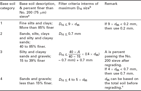
aCategory designation for soil containing particles larger than 4.75 mm is determined from a gradation curve of the base soil which has been adjusted to 100% passing the No. 4 (4.75 mm) sieve.
bFilters are to have a maximum particle size of 3 in. (75 mm) and a maximum of 5% passing the No. 200 (0.075 mm) sieve with the plasticity index (PI) of the fines equal to zero. PI is determined on the material passing the No. 40 (0.425 mm) sieve in accordance with EM 1110-2-1906. To ensure sufficient permeability, filters need to have a D15 size equal to or greater than 4 × d15 but no smaller than 0.1 mm.
cD15 ≤ 4 × d85 should be used in the case of filters beneath riprap subject to wave action and drains which may be subject to violent surging and/ or vibration.
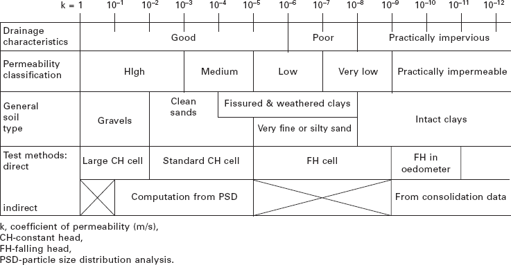
20.3.2 Permeability of soils
The permeability coefficient, also called hydraulic conductivity of the soil in a dam embankment or foundation, is often measured by permeability tests in a laboratory. This property of soils depends on a number of factors. Among these factors are the particle size distribution, particle shape and texture, mineralogical composition, void ratio, degree of saturation, soil fabric, nature of fluid, type of flow and temperature. Table 20.3 shows in general terms the range of permeability which can be encountered.
20.4 Embankment dam construction specifications
Embankment construction methods and testing specifications are intended to ensure that compacted soils are placed uniformly and meet required engineering properties. It is common in embankment construction to prescribe a combination of method and end-result specifications to ensure quality construction. For example, method specifications typically consist of source of construction material, type of rock and degree of weathering, particle size and distribution, upper limit of fines, Atterberg limits, maximum lift thickness requirements, roller type and minimum roller passes, selection and placement of riprap. End-result specifications include specifying 95% of standard Proctor, description of the required soil properties or embankment performance requirements.
Moreover, the question of quality control of earth, earthfill and rockfill dams has been addressed by ICOLD and reported in Bulletin 56 (ICOLD, 1986), which includes inspection, testing and reporting.
20.4.1 Compaction of fill materials during construction
Compaction of soils is one of the methods of soil stabilization. Through compaction, the stiffness and strength properties of the soil are improved and the permeability reduced. The grading of the fill materials is characterized by the grain size distribution curve. Figure 20.4 shows the variation of grain size distribution curves of fill materials from 12 representative earth and rockfill dams in Japan (Narita, 2000). Soil particles of fairly large grain size are used even as impervious core material because of the recent development of heavy equipment and techniques for construction control.
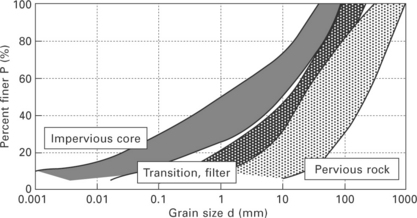
20.4 Typical fill materials (Narita, 2000).
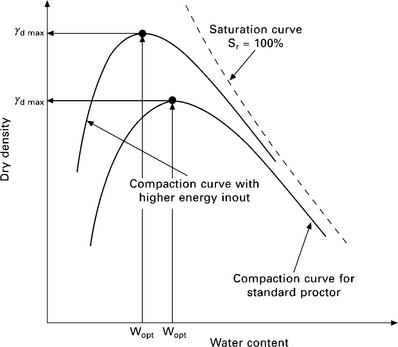
Consider soil compaction under given energy input and with a relatively low water content. By increasing water content step by step, the dry density of soil increases first monotonically because the lubrication effect of water allows particle movement. The dry density of soil decreases however, as the moisture content increases beyond a certain value called the optimum moisture content, wopt. A compaction curve can be plotted, where the peak point is characterized by the maximum dry density, and the optimum water content, wopt. The compaction test was introduced by American engineer R.R. Proctor in 1933 and became widely used around the world. The Proctor test in geotechnical laboratory is used for two purposes: first to find out the suitability of soil as fill with the maximum dry density and the optimum water content; and second to control the compaction quality during construction. In a standard Proctor test, some stipulations are made in terms of energy input and sample size. By using higher energy input, the dry density in construction can be higher than the Proctor density of the same material (Fig. 20.5).
20.4.2 Compaction control
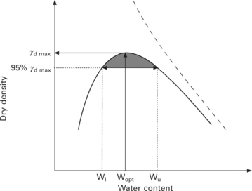
To ensure the required strength, stiffness and permeability of the materials in the field, compaction conditions should be specified in the design stage. The relationship between strength and permeability of compacted soils and dry density are investigated through the use of laboratory test results. The specified after compaction field dry density ρdf is determined so as to satisfy design values of strength and permeability. The field density is determined by either the conventional method (weight and volume) or with a nuclear gauge. This is usually expressed as the relative density D = γdf/γdmax. Consider allowable field water content, compaction quality is controlled to maintain the dry density greater than the specified D-value. Usually the relative density is required to be 90% or 95%. Obviously, the field water content should be within the range between the lower bound w and the upper bound wu (Fig. 20.6).
20.4.3 Particle breakage
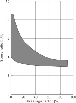
An important issue in the design and construction of rockfill dams is the breakage of the solid particles. Marsal (1967) developed a measure of particle breakage factor, Bg, to quantify particle breakage. His method involves the change in individual particle sizes between the initial (prior to compaction) and final (after compaction) grain size distributions. The difference in the percentage retained is computed for each sieve size. This difference will be either positive or negative. The breakage factor is defined by the sum of the difference having the same sign. Figure 20.7, illustrates the definition of the index Bg (Wang and Sassa, 2000). The breakage index depends on several factors, the stress level and the stress ratio between the major and the minor principal stresses have significant influence on the breakage factor. The dependence of the breakage factor on the stress ratio is shown in Fig. 20.8.
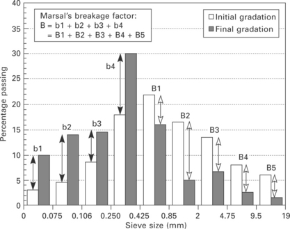
20.7 Definition of the grain breakage factor (Wang and Sassa, 2000)
20.5 Stability analysis of embankment dams
Slope stability analyses of high earth and rockfill dams are very important to ascertain the stability of the structure. As the geotechnical and hydraulic properties of the material in different zones of the earth and rockfill dam differ to a great extent, the static stability of both upstream slope and downstream slope under different conditions have to be analyzed. Moreover, dams located in seismically active areas need to be analyzed extensively to investigate the safety of the structure under dynamic conditions. In fact, the flexibility of dam materials provides excellent seismic stability.
The purpose of slope stability analysis is to provide a quantitative measure of the stability of the slope or a part of the slope. Traditionally it is expressed as a factor of safety against failure of that slope, where the factor of safety is defined as the ratio of the restoring force to the disturbing force, such that factor of safety greater than one shows stability and the factor of safety less than one denotes failure.
The analysis of stability of dams is almost always carried out using limit equilibrium methods. However, in some cases it is necessary to analyze dams using modern numerical analysis tools like the finite element methods and finite difference methods. This may be necessary to predict deformations, and generation and dissipation of pore pressures.
In the modern stability analysis, the finite element and finite difference methods are dominant. In particular the nonlinear effective stress and time domain approaches are leading the seismic design and analysis methods of embankment dams. This is because these methods account for the time varying intensity of ground shaking, and provide insight as to where, when and in what order elements of a dam or foundation respond to excitation. With these modern methods of design and analysis, it is possible to model the problems in three dimensions, to include the entire sequence of events like construction stages, reservoir impounding stages, operation, liquefaction and final configuration of the dam-foundation-reservoir system. Among the nonlinear computer codes used in engineering practice to evaluate the seismic response and deformation of embankment dams are the commercial software DYNAFLOW DIANA, DSAGE, DYNARD, FLAC, DYSAC2 and SWANDYNE4. Another widely used commercial software is GEO-SLOPE for the analysis of slope stability in two dimensions.
20.6 Dam freeboard requirement
Freeboard protects embankment dams from overflow caused by wind-induced tides, waves, landslide and seismic effects, settlement, malfunction of structures and other uncertainties in design, construction and operation. It is defined as the vertical distance between the crest of a dam and a specified pool level, usually the normal operating level or the maximum flood level. Depending on the importance of the structure, the minimum freeboard will vary in order to maintain structural integrity and to reduce the cost of repairing damages resulting from overtopping.
20.7 Failure mechanisms
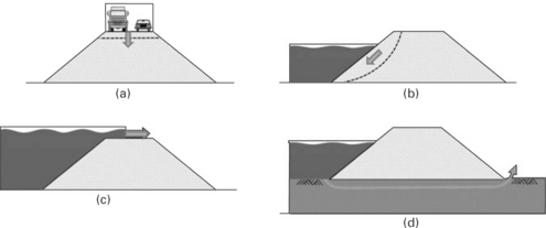
Failure of embankments and dams may assume different forms (Fig. 20.9). Excessive settlement is the most frequently encountered problem for road embankments (Fig. 20.9a). Often poor construction quality is to blame. The loss of slope stability is another oft observed failure form (Fig. 20.9b). Most catastrophic failures of embankment dams are caused by overtopping of the reservoir water due to flooding or loss of freeboard (Fig. 20.9c). Other main factors to cause embankment failures are hydraulic internal erosion (Fig. 20.9c), generation of high pore pressure and earthquake forces. It is interesting to notice that more than 50% of embankment failures in hydraulic engineering are due to hydraulic erosion.
The soil fractions that are considered as most susceptible to erosion are relatively uniform coarse silt and fine sand. Cohesive soils such as clays are more resistant to erosion as long as the chemical bonds are not destroyed (Srbulov, 1988).
20.7.1 Failure due high pore pressure
When soil is saturated and drainage is not provided, the external load is known to be sustained by the inter-granular stress (effective stress) and the pore water pressure. Note that both strength and stiffness of soil are related to the effective stress. This simple but important assumption is known as the effective stress principle by Terzaghi. High water pressure may reduce the effective stress to such an extent that embankments and dams fail. A good example is the construction of embankments on soil as depicted in Fig. 20.10. Along with increasing embankment height, excessive water pressure will generate in the soft soil under the embankment. The dissipation of the excessive water pressure depends mainly on the permeability. As the permeability of soft soil is extremely low, it takes a very long time until the excessive water pressure is completely dissipated. If the embankment construction is too fast, the water pressure generation will exceed the dissipation by a long way, which may lead to ground failure. As a consequence, embankments on soft soil are often constructed in stages. The construction process will be adjusted to the speed of the dissipation of water pressure. There are several techniques to enhance the consolidation of soft soil, e.g. pre-loading, drains and dewatering. Some of these techniques have been successfully used in land reclamation, e.g. the new airport in Bangkok.
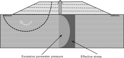
The pore pressure also plays an important role in sand. Whereas the low permeability of soft soil is responsible for the slow dissipation of prepressure, it is the short loading time for sandy soil which is of particular relevance for earthquakes. During earthquakes the ground experiences fast and cyclical loading. The pore pressure generation may exceed the pore pressure dissipation giving rise to excessive pore pressure and reduction of effective stress. If the effective stress vanishes, the soil liquefies and behaves like fluid. Soil liquefaction is responsible for disastrous damage during earthquakes. An example is the Low San Fernando Dam in Southern California, USA, which was damaged by liquefaction during an earthquake in 1971. This failure case alarmed the community and sparked intensive research on liquefaction worldwide. Figure 20.11 shows the numerical simulation of the distribution of pore pressure after the shakes of Low San Fernando Dam (www.geo-slope.com).
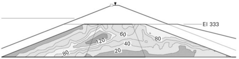
20.11 Distribution of excess pore pressure after shaking (www.geo-slope. com)
20.7.2 Seepage failure
The movement of water in soil is known to obey the law of Darcy, i.e. v = k · i, where v is the flow speed, k the permeability and i the hydraulic gradient. The flowing water also exerts force on the soil, which can be written out readily j = i. γw, where j is the hydraulic force and γw the unit weight of water. For increasing hydraulic gradient, the force j can be so large that the soil grains are suspended and transported through the voids in soil. Such phenomena are known as soil erosion, which can happen at free soil surface, at interface between soil and structure and inside soil.
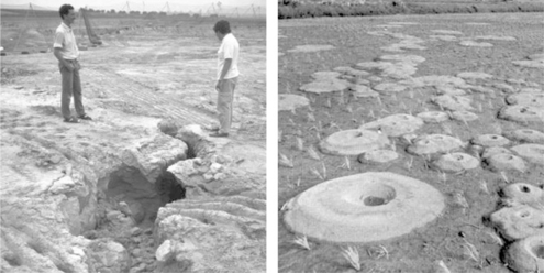
Most embankments exhibit seepage to some extent. However, the rate and quantity of this seepage must be controlled. If uncontrolled, it can erode fine soil material from the downstream slope or foundation and continue moving towards the upstream slope to form a pipe or cavity to the pond or lake, often leading to a complete failure of the embankment (Fig. 20.12). Such internal soil erosions can be often observed in the form of craters formed by the fine soil grains (Fig. 20.12). Seepage failures account for approximately 40% of all embankments or dike failures.
In dam design, filter zones and drains between dissimilar zones, e.g. between rockfill and core, are provided to avoid internal soil erosion. The assessment of the soil erosion potential remains difficult because of the heterogeneous nature of geomaterials. A further important issue is the construction quality. Obviously, a poorly compacted embankment is more prone to piping.
20.7.3 Differential settlement
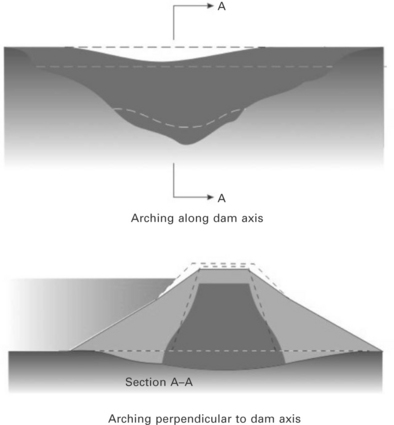
Differential settlement in embankments may be ascribed to the difference in ground conditions, loading conditions and material properties. The latter is particularly true for rockfill dams with an impervious core. Rockfill possesses much higher stiffness than the soft core. Moreover, some arching can be observed even for homogeneous embankments. The differential settlement may lead to internal cracks in the impervious zone and foundation. The differential settlement shows different patterns and the associated deformations appear in the dam body, base foundation and abutments. Figure 20.13 shows the arching effect along the dam axis and perpendicular to the dam axis. Further settlements are caused by first impoundment of the reservoir. Although the rising water table and the buoyancy reduce the effective stress, large settlements are observed during the first impoundment. The mechanism for this settlement is not yet fully understood.
20.7.4 Earthquake damage
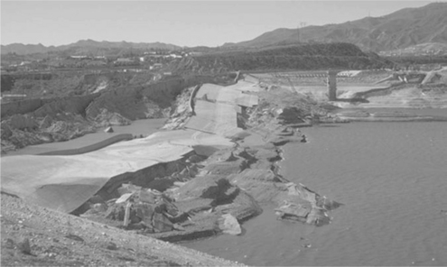
Earthquakes are a major geo-risk for embankments and dams. Embankment failures due to earthquake excitation can be classified into two groups; damage caused by the liquefaction of the dam body and/ or foundation, and the sliding and cracking of the dam body. In the former case, high excess pore pressure is generated during earthquake shakings by the application of cyclic shear stresses. As a consequence, large lateral and vertical deformation displacements are observed. These deformations can lead to catastrophic damages and lead to overtopping and dam break. The damaged Low San Fernando Dam after the earthquake is shown in Fig. 20.14. The dam body literally flew apart. Fortunately, the water table was low and there were no casualties.
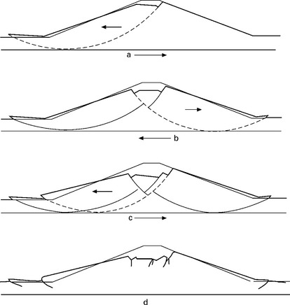
According to the investigation reports on earthquake damage of embankment dams, embankment failures caused by strong excitation are classified into several patterns according to their failure mechanism. Some distinct patterns of embankment failures due to earthquake excitation are schematically illustrated in Fig. 20.15. These failure patterns were obtained from numerical simulations. However, fatal cases of dam failures during earthquakes are rare, which is probably due to the larger safety reserve compared to other engineering structures.
20.8 Maintenance of embankment dams
Due to the long service time, the maintenance of dams and embankments presents an important issue for owners and operators. The dams are to be instrumented and inspected regularly. If problems are identified during an inspection, they should be handled swiftly. Localizing and handling potential problems in the early stage reduces risk and saves time and money. Annual or long-term maintenance programs for earthfill structures may include:
20.9 Future trends
Even though embankment dams have been constructed since ancient times, the mounting demand for renewable energy makes hydropower and therefore dam construction even more appealing. Modern dams can be constructed with impervious membranes of manufactured materials such as concrete, steel, asphalt concrete and geo-synthetics. Dams constructed with such reinforcements are safer against shear failure than conventional earth- or rockfill dams. For a given safety factor, the embankment slopes can be made steeper, the construction time shortened and construction cost reduced.
The market for reinforced soil has developed to maturity, as identified by the increasing number of construction systems.
Embankments are made of unsaturated compacted soil and their behavior is strongly affected by climatic or environmental conditions. When clayey soils are involved, significant ground movement can occur, leading to possible damage to buildings and geotechnical constructions (Arbizzi et al., 2008; Borde and Despres, 2008). More recently, fiber reinforced composites have been widely used as construction materials in various fields from civil engineering to aerospace engineering (Fu et al., 2006; Baklanova et al., 2006; Brownie et al, 1993; Shi et al, 2000). The mechanical properties of soil can be significantly improved by adding fibers to the earth matrix. Fibers of various plant residues present a cost effective way of reinforcing soil. Straw fiber helps to increase strength, control shrinkage cracks and improve toughness (King et al, 2006).
On the other hand, faced with the worldwide shortage of forest resources, industry has shown increasing interest in using agricultural residues for construction purposes (Sampathrajan et al, 1992). Ashour et al. (2010) reported on the effect of straw fibers on the strength and ductility of soils. The effect of plant fibers on the erosion resistance of cohesive soil was investigated by Ashour and Wu (2010). The fiber content has by far the largest influence on the erosion resistance of earth plaster. These and other studies show the great potential of agriculture residues as construction additives.
20.10 Norms and standards
The International Commission on Large Dams (ICOLD at http://www.icoldcigb.net/) has issued numerous recommendations on design, construction, commissioning, operation and maintenance of dams. Usually geotechnical tests for the construction of dams and embankments are carried out in compliance with the national standards. The following list of ASTM standards (American Society of Testing and Materials) applicable to the construction of earthen dams serves as example.
1. ASTM D 421: Practice for Dry Preparation of Soil Samples for Particle Size Analysis
2. ASTM D 422: Method for Particle-Size Analysis of Soils
3. ASTM D 1140: Test Method for Amount of Material in Soils Finer than the No. 200 Sieve
4. ASTM D 1557: Test Methods for Moisture-Density Relations of Soils and Soil Aggregate
5. ASTM D 2216: Method for Laboratory Determination of Moisture Content.
6. ASTM D 2434: Test Method for Permeability of Granular Soils (Constant Head)
7. ASTM D 2487: Test Method for Description and Identification of soils
8. ASTM D 4318: Test Method for Liquid Limit, Plastic Limit, and Plasticity Index of soils
9. ASTM D 4718: Practice for Correction of Unit Weight and Moisture content for Soils Containing Oversize Particles
10. ASTM D 5080: Test Method for Rapid Determination of Soil Density (3-Point Compaction)
11. ASTM D 5084: Test Method for Permeability of Fine Grained Soils (Falling Head)
12. Earth Manual, Third Edition 1998, by the United States Department of the Interior, Bureau of Reclamation (USBR).
13. Engineering Regulations, ER 1110-1-8155, October 2003, Department of the Army, U.S. Army Corps of Engineer (USACE).
14. Design of Small Dams, Third Edition 1987, United States Department of the Interior, Bureau of Reclamation (USBR).
20.11 References
Arbizzi, S., Kreziak, C., Barraud, D., Larrère, F., Souvignet, S., Nagel, B., Analyse d’une base de données ‘pathologies liées à la sécheresse’ et mise en relation avec les sols support. Int. Symposium on Drought and Constructions – SEC2008. LCPC, Paris, 2008:385–391.
Ashour, T., Wu, W. An experimental study on shrinkage of earth plaster with natural fibres for straw bale buildings. Int. J. Sustainable Eng. 2010; 3:299–304.
Ashour, T., Wu, W. The influence of natural reinforcement fibers on erosion properties of earth plaster materials for straw bale buildings. J Building Appraisal. 2010; 5:329–340.
Ashour, T., Wieland, H., Georg, H., Bockisch, F.J., Wu, W. The influence of natural reinforcement fibres on insulation values of earth plaster for straw bale buildings. Mater. Design. 2010; 31:4676–4685.
Baklanova, N.I., Zima, T.M., Boronin, A.I., Kosheev, S.V., Titov, A.T., Isaeva, N.V. Protective ceramic multilayer coatings for carbon fibers. Surf. Coat. Tech. 2006; 201:2313–2319.
Borde, M., Desprès, R., Exemples concrets et illustrés des effets des périodes de sécheresse prolongée sur des constructions situées sur des sols argileux à fort aléa. Int. Symposium on Drought and Constructions – SEC2008. LCPC, Paris, 2008:367–375.
Brownie, P.M., Ponton, C.B., Marquis, P.M., Butler, E.G. Zirconia sol coating of single-crystal ceramic fibres. Mater. Design. 1993; 14:49–51.
Craig, R.F.Soil Mechanics. London, UK: Chapman & Hall, 1992.
EM 1110-2-2300, US Army Engineer Manual. Engineering and design – General design and construction considerations for earth and rock-fill dams. 2004.
Fell, R., MacGregor, P., Stapledon, D., Bell, G.Geotechnical engineering of dams. Leiden: Balkema, 2005.
Fu, Y.C., Shi, N.L., Zhang, D.Z., Yang, R. Effect of C coating on the interfacial microstructure and properties of SiC fiber-reinforced Ti matrix composites. Mat. Sci. Eng. A-Struct. 2006; 426:278–282.
GEO-SLOPE International Ltd, Calgary, Alberta, Canada (www.geo-slope.com).
Head, K.H., Manual of Soil Laboratory TestingVol. 2: Permeability, Shear Strength, and Compressibility Tests. London: Pentech Press, 1982.
ICOLD (International Commission on Large Dams). Quality control for fill dams. Bulletin. 56, 1986.
King, B., Aschheim, M., Dalmeijer, R., Donahue, K., Hammer, M., Smith, D.Stone N., Straube J., Summers M., Theis B., eds. Design of Straw Bale Buildings: the State of the Art. Green Building Press: 2006:19–55.
Marsal, R.J. Large scale testing of rockfill materials. J. Soil Mech. Found. Eng. Division. 1967; 93:27–43. [ASCE].
Narita, K., Design and construction of embankment damsResearch Report. Japan: Deptartment of Civil Engineering, Aichi Institute of Technology, 2000.
Sampathrajan, A., Vijayaraghavan, N.C., Swaminathan, K.R. Mechanical and thermal properties of particleboards made from farm residues. Bioresour. Technol. 1992; 40:249–251.
Shi, Z.F., Zhou, L.M. Interfacial debonding of coated-fiber-reinforced composites under tension-tension cyclic load. Acta Mech. Sinica. 2000; 16:347–356.
Srbulov, M. Estimation of soil internal erosion potential. Computers andGeotechnics. 1988; 6:265–276.
Tensay, G.B., Wang, X.T., Wu, W., Numerical Investigation into the Arrangement of Clay Core on the Seismic Performance of Earth Dams. Geotechnical Special Publication, Soil Dynamics and Earthquake Engineering. 2010:375–384. [ASCE].
Wang, F.W., Sassa, K. Relationship between grain crushing and excessive pore water pressure generation by sandy soil in ring shear tests. Journal of Natural Disaster Science. 2000; 22:87–96.