
Chapter 24
Polymeric Insulators in the Electrical Engineering Industry: Examples of Applications, Constraints and Perspectives 1
24.1. Introduction
From the electric power station to the final user, electricity is transported through the medium of high voltage networks, i.e. 1kV to 1,000 kV, and even to 1,200 kV. To ensure the security of electricity supply, the durability of the different electrical equipment used in these networks – transformers, circuit-breakers, lines and cables, etc. – is obviously essential.
Actually, the reliability of this type of product strongly depends on insulating structures and materials. These insulating pieces and structures also play a major role in technical performance and in the cost price of this equipment.
This chapter tackles the main aspects of the engineering of insulating materials for electrical engineering applications, by presenting the typical constraints for the use of high voltage equipment through examples of applications, and then by evoking the possible evolution of the insulation world.
For engineering aspects, the case of high voltage equipment or power transformers is particularly emphasized. However, cables or rotating machines, (such as generators or motors) which are not discussed here, have the same problems and therefore very similar structures, even though thermal or environmental stresses are a bit different.
As for the evolution perspectives, we shall answer the question of optimization of electrical behavior and the prediction of ageing by means of, on the one hand, numerical simulation, and on the other hand by the control of the evolution of the electrical characteristics related to microstructural changes due to ageing.
We shall also deal with the impact of environmental questions on these materials and the possibilities of reducing their environmental impacts via eco-design.
24.2. Equipment
High voltage equipment is conceived to operate in complete safety at nominal currents in normal network conditions but also to face short circuit currents occurring under fault conditions, during the closing or opening of electrical circuits.
When they are open, the equipment must also safely insulate different parts of the network.
24.2.1. Arc commutation
In general, during current breaking operations (Figure 24.1), an electric arc is initiated between contacts (7) and (8) and transmits its energy to the thermal expansion volume Vt, generally filled with SF6 gas, a very good dielectric.
During the passage of the current through zero, the created overpressure is discharged through the insulating nozzle (9) and within the mobile contact (7). This double blowing allows the arc to be cooled effectively and cuts the current.
In the arc switching chamber, the insulation nozzle is submitted to strong stresses.
It must indeed support the high dielectric gradients and the ultraviolet radiation induced by the de-excitation of gas molecules and other constituents of the arc plasma, such as metal vapors and materials coming from the erosion of the walls of the arcing chamber or the nozzle.
The nozzle must also sustain high temperatures generated by the arc, and resist projections of metal vapors and droplets [AES 02].
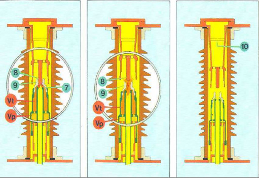
Figure 24.2. (a) Nozzle and contact of the equipment (1: ablation zone of the nozzle) (b) Microstructure of the nozzle (1: mineral charge – 2: PTFE)
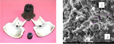
This leads to a degradation of the nozzle (Figure 24.2), whose material is generally composed of polytetrafluoroethylene (PTFE) filled with mineral additives.
Studies undertaken on the arc/nozzle interaction have proved that during the extinction of the arc, the erosion of the nozzle is mainly due to photo-ablation. In terms of composite structure, the mineral charges and the microstructure of the PTFE play a major role in this phenomenon, by influencing the absorption and the diffusion of UV radiation emitted by the arc (Figure 24.3) [FER 96].
Figure 24.3. Radiation/PTFE interactions – a) Intensity transmitted as a function of temperature; b) Schematic showing the multiple reflections between crystallites
Indeed, the dielectric properties of the PTFE, and particularly their stability, are also essential to ensure the insulation capacity of the arcing chamber. Particular attention should be brought to the influence of humidity, as we can see in Figure 24.4 in the case of PTFE filled with CaF2 [ETI 00].
Figure 24.4. Evolution of the real (ε‘) and imaginary parts (ε”) of the complex permittivity as a function of the material exposition (PTFE/CaF2) to ambient air
24.2.2. Composite insulators
Generally, the external insulators of high voltage equipment are composed of aluminous electrotechnical porcelain. This material is well-known and its ageing is very good. However, ceramic insulators are heavy, fragile and, in heavily polluted areas, must often be cleaned.
Composite insulators are therefore more and more commonly used, because they present appealing advantages compared with ceramic insulators. They do not explode in case of impact; they are flexible and light and allow a combination of functions – for example for the use of optical fiber systems.
However, the specifications for such insulators are fairly strict. Indeed, they must present a very good fit, as gas leaks at the equipment level must be lower than 0.5% per year. These insulators must also support any type of atmospheric conditions which might risk affecting their dielectric, mechanical, or watertightness characteristics.
In general, these materials and structures present a lifetime of 20 to 30 years at least, for whatever type of atmosphere (with industrial pollution, marine environment, etc.), and can be installed in conditions of extreme temperatures, from -60°C (in certain cases) up to an ambient temperature of 50°C, leading to particularly high operating temperatures (100°C at least).

In such a structure (Figure 24.5), the materials used must have a very good lifetime under voltage, with low dielectric losses as well as good resistivity and chemical resistance characteristics. The composite tube is generally made with epoxy resin reinforced with fiberglass. The winding angle is about +/- 55° in order to withstand bending and pressure stresses and an internal polyester layer is generally added to improve the stability to the arc radiation, or to acids coming from the decomposition of the SF6 gas.
The extremities are glued to the composite tube before being coated with the shedding material – a silicone elastomer is the most commonly used – which then covers the metallic end-fittings.
These insulators are used for circuit-breakers, measurement transformers, or as bushings (on transformers or sub-stations, for example), but also as insulating enclosures for surge arresters [KIE 05]. This type of structure – with a solid core – is also used as support insulators (of conductive bars for, example), or suspension line insulators for use on overhead lines.
During the design and selection of materials, the quality of the insulation is one of the essential parameters to control, in order to ensure the durability of the insulation offered by these insulators. For example, the current leakage obtained for a given voltage, as a function of the climatic events and ageing (Figure 24.6), allows a distinction to be made between diverse materials.
Figure 24.6. Example of the evolution of the leakage current as a function of the blade material of an insulator
24.3. Power transformer insulation
A power transformer is one of the most expensive strategic components of transmission and distribution electrical network, and the reliability of these networks strongly depends on the reliability of this type of equipment. Actually, the deterioration of the insulation represents the most frequent cause of failure of transformers.
The insulation of these pieces of equipment can be considered as a typical composite structure. Indeed, it is composed of a combination of insulating solid and liquid materials in which the solid material acts as a mechanical and electrical separation between the conductors (copper or aluminum) or between two loops of a coil.
For such insulation, cellulose has been used for over 100 years, mainly for economical reasons, despite numerous investigations undertaken to replace it by more effective materials. Aramid paper is also used, particularly for applications submitted to high temperatures (i.e. operating temperatures greater than 100°C).
Insulating liquid, mainly mineral oil, is extremely compatible with cellulose and presents good thermal exchange characteristics, acting as an insulator and heat transfer agent.
In this type of insulation, the control of the interactions between cellulose, water and oil, is of particular importance to ensure the durability of the insulation. Over time, a cellulose depolymerization phenomenon occurs, and therefore a degradation of the papers, cardboards and woods appears.
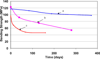
As can be seen in Figure 24.7, the mechanical performance of a cellulose material can thus be reduced by 50% in a relatively short time, compared with the lifetime of a transformer (over 40 years) [KIE 06].
Figure 24.7. Stress at the breakdown (4-point bending) as a function of ageing at 95°C with a humidity rate of 3% (a), 6% (b) and 10% (c) – the case of lamelled glued wood
24.4. Perspectives
During the past twenty to thirty years, under the effect of the opening of markets and the reduction of electrical equipment programmes in numerous countries, the manufacturers of electric materials have been subjected to a heavy pressure on prices. This has led them to introduce numerous innovations towards the functional and economical optimization of products and materials, while improving their reliability.
Today, under the effect of the economic dynamism of emerging countries, and with the arrival of numerous pieces of equipment in occidental countries at the end of their lives, a resurgence in the demand for electrical products associated with a renewal of clients’ expectations can be seen. This offers manufacturers with new technological innovation opportunities and allows new paths of investigations to be conceived.
In the first place, the question of the performance improvements of insulators is, and will remain, topical for a very long time.
Whether it is to increase the lifetime or reliability, to reduce the dimensions or the costs, the natural trend is to increase the breakdown voltage of insulators as much as possible, and to make this characteristic remain stable over time.
The modeling of the microscopic configuration of the electric field as a function of the electrical properties of different phases present in the material, or breakdown mechanisms, can bring interesting answers to this question. For example, the influence of the presence of different types of particles on the propagation of a discharge can be simulated (Figure 24.8) [FLA 02]. The effect of the granulometric distribution of charges on breakdown can thus be estimated, giving indications of the interest in using nano-particles in such insulating materials.
Today these tools are still at the development stage and, if 2D modeling is fairly accessible, 3D modeling still requires much research. In particular, the correlation between calculations and experiments remains to be established systematically.
The possibility of predicting the remaining lifetime of an insulating piece, from a diagnosis of its state of ageing, is also an important subject.
Indeed, numerous equipments installed from the fifties to the seventies are now reaching their theoretical lifetime limit. Network operators and electricity manufacturers therefore ask themselves, rightly, if the use of this equipment can be prolonged and, in that case, if the risk of accidental failure can be avoided.

This worry has already initiated many studies. For example, in the case of bulk insulating materials, such as epoxy charged with particles (silicone, calcium carbonate, etc.), the revealing of a correlation between the evolution of electrical characteristics, change in microstructure, and chemical evolution with respect to ageing is well established (Figures 24.9 and 24.10) [VOU 06].
Figure 24.10. Dielectric permittivity at 1 kHz of the new epoxy/alumina composite ( ![]() 1st scan,
1st scan, ![]() 2nd scan) and 6 month old (
2nd scan) and 6 month old ( ![]() 1st scan,
1st scan, ![]() 2nd scan)
2nd scan)
Other research can also be mentioned. For example the ageing state in transformers can be estimated by following the evolution of the chemical composition of oil by gas phase chromatography. The ageing of cables too, can be particularly studied by following the evolution of the distribution of space charges as a function of time.
These techniques have started to be used systematically in laboratories, and one may think that they will undergo an important development in the future.
Finally, in the domain of insulation, like in other technical domains, eco-design will represent an important means for innovation in the future. Because of the evolution of western society and its regulations, the environmental issue becomes more and more important. To face it, eco-design approaches have been developed by manufacturers, allowing, owing to a rational approach, the environmental impacts of products to be reduced, with a limited economic impact.
Thus, the improvement of recyclability (for example by using thermoplastics instead of thermosets [BES 05] or by avoiding mixtures of materials, making those inseparable at the end of life) constitutes a priority route of environmental improvement.
The use of dangerous substances (CMR: Carcinogenic, Mutagenic, Repro-toxic) in insulators is a more complex issue. Whether it is substances recording (in application of the European directive REACH), reduction of volatile organic compounds (VOC) or elimination of heavy metals or flame retardants, the evolution of authorized substances should, in the coming years, strongly impact on the formulation and the engineering of polymers, and therefore on their properties.
Furthermore, the more common use of environmental evaluations to cover the entire life cycle of products as evaluation tools, even the choice of materials, will also have an important impact on the electrical insulator sector.
24.5. Conclusion
As can be seen in this chapter, polymeric insulating materials, because of their properties and their versatilities, are likely to respond to a wide range of applications and solicitations.
They are often used in a “composite” form allowing complex parts with multiple functions to be obtained by combining different properties. Different polymers can thus be associated together, or polymers can be associated with mineral elements such as fiberglass, mineral powders, etc. Polymers can also be associated with liquids, and thus cover a whole range of insulation functions.
Depending on the application and the function to be realized, all the dielectric properties can be used to characterize and specify the materials used in electrical engineering applications. However, these are not sufficient and (as we have seen) radiation absorption characteristics, microstructural characteristics, or even mechanical characteristics are also very useful.
In the future, the technological evolutions that will prevail will be those which allow manufacturers to best meet the new expectations of their clients (essentially electrical network operators).
On this account, the new electrical properties simulation tools, the ageing studies aimed at revealing correlations between the evolution of microstructures and their properties, and eco-design methodology are the key domains in which research efforts will continue. Any progress made will then allow the designing of future insulators to better answer the needs of performance improvement, lifetime prediction, or the considerations of environmental impacts.
24.6. Bibliography
[AES 02] AESCHBACH H., VISATA O., DUFOURNET D., BESSÈDE J-L., BLATTER J., “Arcing-Contact/Insulating-Wall Interactions in High Voltage Circuit Breakers”, Proceeding of 21st International Conference on Electrical Contacts, Zurich, Switzerland, p. 511–517, September 2002.
[BES 05] BESSÈDE J-L et al., “Suitability of Polyethylene Terephtalate for the making of HV GIS Insulator”, IEEE Conference on electrical insulation and dielectric phenomena, Nashville, USA, paper ID 306, 2005.
[ETI 00] ETIENNE S., STOCHMIL C., BESSÈDE J-L., “Dielectric properties of polymer-based Micro-heterogeneous Insulator”, 12th int. conf. on internal friction and ultrasonic attenuation, Buenos Aires, Argentina, 19–23 July 1999, J. of Alloys and Compounds, 310, p. 368–373, 2000.
[FER 96] FERRY L., VIGIER G., BESSÈDE J-L., “Effect of ultraviolet radiation on polytetrafluoroethylene: morphology influence”, Polymers for Advanced Technologies, vol. 7, nos. 5 & 6, p. 493–500, 1996.
[FLA 02] FLANDIN L., VOUYOVITCH L., BESSÈDE J-L., BÉROUAL A., ALBÉROLA N.D., “Modeling of dielectric breakdown in epoxy based heterogeneous systems”, 9th INSUCON International Electrical Insulation Conference, Berlin, 18–20 June 2002.
[KIE 05] KIEFFEL Y., HERMOSILLO V., MISTIAEN B., PUYANÉ R., HASSANZADEH M., BESSÉDE J-L., “Experience with hollow core composite insulators at AREVA T&D - Research and applications”, INMR 2005 World Insulator Congress, Hong-Kong, November 2005.
[KIE 06] KIEFFEL Y., BESSÈDE J-L., PERRIER C., DEVAUX F., SARAVOLAC M., LONG P., “Improvement of the reliability of power transformer insulation”, 10th INSUCON International Electrical Insulation Conference, Birmingham, UK, 24–26 May 2006.
[VOU 06] VOUYOVITCH L., FLANDIN L., BESSEDE J-L., ALBEROLA N.D., “Evolutions of Microstructure and Dielectric Behaviour of Epoxy Based Insulator-Insulator c composites over Long Periods of Time”, Journal of Applied Polymer Science, vol. 100, p. 3454– 3464, 2006.
1 Chapter written by Jean-Luc BESSEDE.