
Chapter 8
Biomass Energy Systems
8.1 Biomass Energy
The term biomass is used for materials derived from plants and animals, including their wastes and residues. Biomass is produced by green plants that use the energy of sunlight to convert carbon dioxide and water into simple sugar and oxygen. The energy obtained from biomass is known as biomass energy. Photosynthesis is fundamental to the conversion of solar radiation into stored biomass energy. The initial energy in the biomass system is obtained from solar radiation in the form of photosynthesis. In plants, algae and certain types of bacteria, the photosynthetic process results in the release of molecular oxygen and the removal of carbon dioxide from the atmosphere that is used to synthesize carbohydrates (oxygenic photosynthesis). This conversion process consists of a series of chemical reactions that require carbon dioxide (CO2) and water (H2O) and store chemical energy in the form of sugar. Light energy from the Sun drives these reactions. Oxygen (O2) is a by-product of photosynthesis and is released into the atmosphere. The following equation summarizes photosynthesis:
The reaction produces ![]() which is glucose and oxygen which is released into atmosphere. The theoretical achievable efficiency of conversion is limited by both the limited wavelength range applicable to photosynthesis and the quantum requirements of the photosynthetic process. Because of these limitations, the theoretical maximum efficiency of solar energy conversion is approximately 11%. In practice, however, the magnitude of photosynthetic efficiency observed in the field is further decreased by factors such as poor absorption of sunlight due to its reflection, respiration requirements of photosynthesis and the need for optimal solar radiation levels. The net result is an overall photosynthetic efficiency of between 3% and 6% of total solar radiation [1]. When these carbohydrates are burnt, they are converted back into carbon dioxide and water and release the energy they captured from the Sun. The biomass can be used to produce energy using any of the following methods:
which is glucose and oxygen which is released into atmosphere. The theoretical achievable efficiency of conversion is limited by both the limited wavelength range applicable to photosynthesis and the quantum requirements of the photosynthetic process. Because of these limitations, the theoretical maximum efficiency of solar energy conversion is approximately 11%. In practice, however, the magnitude of photosynthetic efficiency observed in the field is further decreased by factors such as poor absorption of sunlight due to its reflection, respiration requirements of photosynthesis and the need for optimal solar radiation levels. The net result is an overall photosynthetic efficiency of between 3% and 6% of total solar radiation [1]. When these carbohydrates are burnt, they are converted back into carbon dioxide and water and release the energy they captured from the Sun. The biomass can be used to produce energy using any of the following methods:
- Burned in power plants to produce heat or electricity, with fewer harmful emissions than coal.
- Fermented to produce fuels, such as ethanol, for cars and trucks.
- Digested by bacteria to create methane gas for powering turbines.
- Heated under special conditions, or “gasified”, to break down into a mix of gases that can be burned for electricity or used to make a range of products, from diesel to gasoline to chemicals.
In this way, biomass can be considered as a sort of natural battery for storing solar energy. Biomass takes carbon out of the atmosphere while it is growing and returns it as it is burnt. If it is managed on a sustainable basis, biomass is harvested as part of a constantly replenished crop such as fast-growing willow trees. This maintains a closed carbon cycle with no net increase in atmospheric CO2 levels. If the consumption does not exceed its natural level of production, the burning of biomass will not generate more heat or carbon dioxide than would have been formed by the natural process.
As described in this section, a wide variety of fuels can be considered as “biomass”. These include animal manure, landfill waste, wood pellets, vegetable oil, algae, crops such as corn, sugar, switchgrass and other plant material – even paper and household garbage – can be used as a biomass fuel source. Various biofuel resources are shown in Fig. 8.1.

Figure 8.1 Different biomass resources.
Fossil fuels such as coal, oil and gas are also derived from biological material; however, they absorbed CO2 from the atmosphere many millions of years ago. The vital difference between biomass and fossil fuels is one of time scale. That is why fossil fuels are not considered as renewable because they are out of carbon cycle for a very long time. Fossil fuels offer a high energy density when burnt. By doing this, the stored carbon is oxidized into carbon dioxide and the hydrogen into water (vapour). If these emissions are not captured and stored, they are released back into the atmosphere, thus returning the carbon captured millions of years ago and thus adding to increased amounts of CO2 into the atmosphere.
There are a number of conversion technologies used for the production of power and heat as well as transportation fuels. Biomass fuel can be converted directly into heat energy through combustion, similarly to the burning of a log. However, in most cases, biomass is converted into a more convenient form, by chemical or biological process, to produce biofuels. Examples of biofuels include methane gas, liquid ethanol, oils and solid charcoal. The biofuels react with oxygen to release heat, and the energy is dissipated.
8.2 Biomass Production
There is a wide variety of biomass feedstocks available, and they can be produced anywhere in the world. Every region has its own locally generated biomass feedstocks from agriculture, forest and urban sources Furthermore, most feedstocks can be made into liquid fuels, heat, electric power and/or biobased products.
The two groups of feedstocks primarily responsible for producing biomass fuels are as follows:
- Group I Sources:
- Forest industries
- Agriculture.
- Group II Sources:
- Food waste
- Industrial waste and co-products
In the first category, the biomass may consist of sawdust which is produced when a log is cut to make lumber in lumber mills and logging by-products. A lot of biomass fuels are available as by-product from other activities, such as saw milling and manufacturing of plywood and particle board.
Energy crops (switchgrass), crop residue and so on are also included in the first group. Forest industry provides biomass materials as by-products such as logging residues and as main products which are cut directly from trees and forests. The planted forests are usually thinned out to maintain the growth space among stumps. The woody material thus cut is utilized as biomass.
Dedicated energy crops are another source of woody biomass for energy. Short-rotation (3–15 years) techniques for growing poplar, willow, Eucalyptus or even non-woody perennial grasses (e.g. Miscanthus) have been developed over the past two to three decades.
In the second category, the biomass may come from construction or organic municipal waste, food waste and even chicken litter. Food wastes are generated in restaurants, supermarkets, residential blocks, cafeterias, airline caterers, food processing industries and so on. In most of the cases, it is dropped in landfill sites and is left to rot, thereby releasing greenhouse gases in the atmosphere. Anaerobic digestion (AD) can be used as described later to convert this waste into energy. Industrial waste energy recovery and recycling come under the technology of cogeneration or combined heat and power (CHP) generation. Energy recovery from municipal wastes known as MSW and from some of the industries is also possible and is being utilized.
Since the rapid expansion of biomass energy today relies largely on wood from forests, the energy produced by the combustion of biomass from forest wood and woody residue as well as other technologies for the generation of energy is discussed here.
8.2.1 Forest Industries
Wood is the first biomass resource which has been used by human beings as fuel for cooking for the last few centuries. Wood is one of the oldest energy sources and has been in constant use throughout the modern era, despite the widespread adoption of other types of fuels. Even now, more than 2 billion people depend on wood energy for cooking and/or heating, in households in developing countries. It represents one-third of the global renewable energy consumption, making wood the most decentralized energy in the world. Forests are a major source of woody biomass. However, woody materials can also be sourced from agriculture. For example, fast-growing tree species such as hybrid willow (Salix) and poplar have been developed for the production in agricultural settings (i.e. grown as row crops on farms).
Today, wood energy has become an important source of green energy because of climate change and energy security concerns. Wood energy is considered as a climate neutral and socially viable source of renewable energy, provided the trees harvested as biomass are re-planted as fast as the wood is burnt. In such condition, the new trees absorb the carbon dioxide produced by the combustion of old trees, and the carbon cycle theoretically remains in balance. Thus, no extra carbon is added to the atmospheric balance sheet. Biomass can only maintain carbon balance if fast-growing crops are grown on otherwise unproductive land; in this case, the re-growth of the plants offsets the carbon produced by the combustion of the crops. But cutting or clearing forests for energy, either to burn trees or to plant energy crops, releases carbon into the atmosphere that would have been remained stored if the trees had remained untouched.
Biomass for fuel can be gathered as waste or grown in fields. The most common biomass resources are therefore from agricultural and forestry. Forest residues and wood wastes represent a large potential resource for energy production and include forest residues, forest thinnings, and primary mill residues [2]. But the energy potential of waste biomass is relatively small compared to the virgin biomass as an energy resource. The key to the large-scale production of energy, fuels, from biomass is to grow suitable virgin biomass species in an integrated biomass-production conversion system (IBPCS) at costs that enable the overall system to be profitable.
Even though the costs for these fuels are usually greater than that of coal, they reduce the fuel price risk by diversifying the fuel supply. These also result in significantly lower sulfur dioxide and nitrogen oxide emissions compared to coal and can easily be cofired. [3]
8.2.2 Forest Residues
Forest residues are the biomass material remaining in forests from harvest operations that are left in the forest after stem wood removal, such as branches, foliage and roots. Harvesting may occur as thinning in young stands or cutting in older stands for timber or pulp that also yields tops and branches usable for biomass energy production. Harvesting operations usually remove only 25–50% of the volume, leaving the residues available as biomass for energy. Stands damaged by insects, disease or fire are additional sources of biomass. Forest residues normally have low density and fuel values that keep transport costs high, and so it is economical to reduce the biomass density in the forest itself.
Since lumber mills and other processing facilities use timber of certain quality, forest residues are left in the forest. These residues could be collected after a timber harvest and used for energy purposes. Typically, forest residues are either left in the forest or disposed of via open burning through forest management programs. The primary advantage of using forest residues for power generation is that an existing collection infrastructure is already available to harvest wood in many areas.
8.2.2.1 Forest Thinnings
Thinning of forest removes surplus trees to concentrate timber production plantation resulting in increased diameter growth and producing more valuable trees. Underbrush and saplings smaller than 2 inches in diameter, as well as fallen or dead trees, are also considered as forest thinnings. However, the actual business of harvesting, collecting, processing and transporting loose forest thinnings is costly and presents an economic barrier to their recovery and utilization for energy. Typically, the wood waste from forest thinnings is disposed of through controlled burning due to the expense of transporting it to a power generation facility.
8.2.3 Agriculture Residues
Agriculture residues are traditionally considered as “trash”, or agricultural waste is increasingly being viewed as a valuable resource. Agricultural residues such as straw, rice husk, coconut shell, groundnut shell and sugar cane bagasse are an excellent alternative to using virgin wood fibre as they have many advantages. These are available in abundance and are renewable. Rice produces both straw and rice husks at the processing plant which can be conveniently and easily converted into energy. Significant quantities of biomass remain in the fields in the form of cob when maize is harvested which can be converted into energy. Sugar cane harvesting leads to harvest residues in the fields while processing produces fibrous bagasse, both of which are good sources of energy.
Rice, wheat, sugar cane, maize (corn), soybeans and groundnuts are just a few examples of crops that generate considerable amounts of residues. Following the harvest of these agricultural crops, residues such as crop stalks, leaves and cobs are left in the field. A segment of these residues could potentially be collected and combusted to produce energy. These residues constitute a major part of the total annual production of biomass residues and are an important source of energy for both domestic and industrial purposes. However, transportation of residues can be expensive and not highly energy efficient.
8.2.4 Energy Crops
Dedicated energy crops are another source of woody biomass for energy. These crops are fast-growing plants, trees or other herbaceous biomass which are harvested specifically for energy production. Crops such as switchgrass, hybrid poplars (cottonwoods), hybrid willows and sugar cane are being studied for their ability to serve as energy crops for fuel. These crops have the greatest potential for dedicated energy use over a wide geographic range. One of their great advantages is that they are short rotation crops; they re-grow after each harvest, allowing multiple harvests without having to re-plant. Corn and sorghum serve a dual purpose as they can be grown for fuel, with the leftover by-products being used for other purposes, including food. Similarly, sugar cane crops are used for food (sugar) and energy in the form of ethanol. Oil-bearing trees such as soya bean, corn, sunflower, soybean, castor and wild plants such as jatropha and karanj are used to produce biodiesel. Sugar cane is a major source for bioethanol. Jatropha is a shrub that grows up to 5 m in height. It can be planted even in desert and can be grown in places where no crop is grown normally. These can be used for energy production after 2–3 years.
Karanj is another wild tree which is generally used to stop soil corrosion along highways and canals. The natural growth of karanj is along coasts and river banks in India and Myanmar. It is now also grown in the Philippines, Malaysia, Australia and Seychelles. Miscanthus (commonly known as Elephant Grass) is a high-yielding energy crop that grows over 3 m tall, resembles bamboo and produces a crop every year without the need for re-planting. The rapid growth, low mineral content and high biomass yield of Miscanthus increasingly make it a favourite choice as a biofuel, outperforming maize (corn) and other alternatives. Biodiesel can be produced from non-food feedstock. This means that the feedstock does not serve to diminish food supply. It also means that feedstock used for biodiesel can be shielded from global commodity prices.
Thus, a significant and increasing fraction of agricultural land worldwide is likely to be dedicated to the production of energy crops in the near future. This is a matter of concern that cultivation of energy crops might reduce land availability for food production.
8.2.5 Food and Industrial Wastes
While there is an obvious need to minimize the generation of wastes in cities and to reuse and recycle them, the technologies for recovery of energy from wastes can play a vital role in mitigating the problems. Besides recovery of substantial energy, these technologies can lead to a substantial reduction in the overall waste quantities requiring final disposal, which can be better managed for safe disposal. Food processing wastes are being used throughout the world as biomass feedstocks for energy generation. These wastes include house garbage, also called municipal solid waste (MSW), trash that comes from plant or animal products, food waste from restaurants. Many food materials are processed at some stage to remove components that are inedible or not required such as peel/skin, shells, husks, cores, pips/stones, fish heads, pulp from juice and oil extraction. Through a process called co-digestion, many treatment plants are enhancing AD with organic waste. Adding fat, oil and grease (FOG), as well as food waste, to AD accelerates this process, producing more methane gas for beneficial use and reducing the amount of solid waste conveyed to landfills.
Lawn clippings and leaves are all examples of biomass trash. Animal farms are also producing wastes that are not converted into fuels at present. These wastes are contributing to environmental degradation because many municipalities have not yet used them in energy conversion. Because of the necessity to generate energy locally, biomass resources such as MSW and sewage will become important in the future. MSW can be used to produce energy by either burning MSW in waste-to-energy plants or capturing biogas.
At an MSW combustion facility, MSW is first sorted, and items that can be recycled are removed from the waste. The material that is left is sent into a combustion chamber to be burnt. The heat released from burning is used to convert water to steam. The steam is then sent to a turbine generator to produce electricity.
8.3 Biomass Conversion Process
Biomass can be converted into useful forms of energy using a number of different processes. Factors that influence the choice of conversion process are the type and quantity of biomass feedstock; the desired form of the energy, that is, end-use requirements; environmental standards; economic conditions; and project-specific factors. The main application of biomass is to
- 1. transform the chemical energy into electrical energy and
- 2. production of biofuel.
Currently, conversion of biomass to energy is undertaken using three main process technologies [4]:
- thermochemical
- biochemical/biological
- mechanical extraction (with esterification)
8.4 Thermochemical Conversion
The main processes used for the thermochemical conversion of biomass are combustion, gasification, pyrolysis and liquefaction. The thermochemical processes can convert both food and non-food biomass to fuel products via pyrolysis and gasification [5, 6]. Charcoal is one of the major commercial products of biomass pyrolysis and is the largest single biofuel produced today. Common feedstock for gasification includes agricultural crop residues, forest residues, energy crops, organic municipal wastes and animal waste.
8.4.1 Combustion
Biomass conversion into heat energy is still the most popular and perhaps the most efficient process using combustion. The most common application of biomass energy in developing countries is its use as a source of heat for cooking, sometimes called traditional biomass use. The burning of biomass in air, that is, combustion, is used over a wide range of outputs to convert the chemical energy stored in biomass into heat, mechanical power or electricity. Combustion of biomass produces hot gases at temperatures around 800–1000°C. It is possible to burn any type of biomass, but in practice, combustion is feasible only for biomass with a moisture content <50%, unless the biomass is pre-dried. High-moisture-content biomass is better suited to biological conversion processes. The heat is then used in a manufacturing process or to raise steam in a boiler which can drive a steam turbine to generate electricity. Net bio-energy conversion efficiencies for biomass combustion power plants range from 20% to 40%. The higher efficiencies are obtained with systems over 100 MW or when the biomass is co-combusted in coal-fired power plants.
The size of combustion system has a very wide range from a few kilowatts of thermal input such as a single gas ring for cooking to huge coal-fired combustion boilers with inputs of 3–5 GW in a single unit.
8.4.2 Gasification
Gasification is a thermochemical process where solid biomass is converted into gaseous fuel without leaving any solid residue. It is a well-established technology and was extensively used in World War II to power vehicles for transport. Gasification is the conversion of biomass into a combustible gas mixture by the partial oxidation of biomass at high temperatures, typically in the range of 800–900°C. The main components of this gas are CO, H2, CO2, CH4, H2O and N2. However, a variety of tars are also produced during the gasification reaction. The partial oxidation can be carried out using air, oxygen, steam or a mixture of all of these. Air gasification produces poor quality of gas in terms of heating value. Oxygen gasification provides better quality gas in terms of energy contents. The production of syngas from biomass allows the production of methanol and hydrogen, each of which may have a future a fuel for transportation. Figure 8.2 shows a schematic diagram that illustrates the biomass gasification technology.
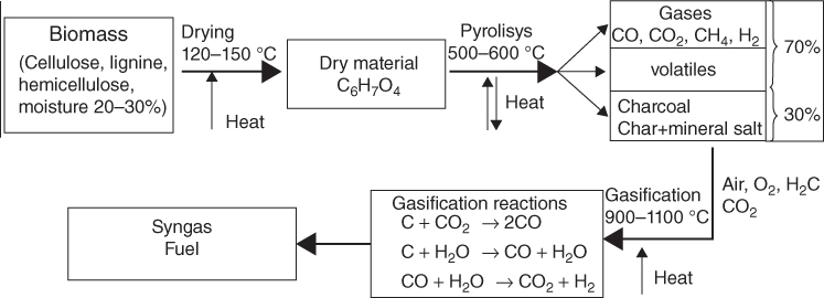
Figure 8.2 Gasification flow diagram.
The conversion of biomass by gasification into a fuel is most suitable for use in an IC engine.
Basic chemical reactions in the gasification process for producing syngas are
Since there is an interaction of air or oxygen and biomass in the gasifier; these are classified according to the way air or oxygen is introduced in it as downdraft, updraft, cross-draft and fluidized bed. In an updraft gasifier, air or oxygen passes through the biomass from the bottom and the combustible gases come out from the top.
The updraft gasifier is the simplest type of reactor for the gasification of biomass that is easy to operate and has high conversion efficiency, although it produces high levels of tar. Because it has high tar content, these are not suitable for internal combustion engine. Updraft gasifiers shown in Fig. 8.3 achieve the highest efficiency as the hot gas passes through fuel bed and leaves the gasifier at a low temperature. The sensible heat given by gas is used to pre-heat and dry fuel. The gas produced has practically no ash content.

Figure 8.3 Updraft gasifier.
In downdraft gasifiers shown in Fig. 8.4, gas is drawn from the bottom of the reactor while the hottest reaction zone is in the middle. It is suitable for a variety of biomass materials. The biomass fuel enters through the hopper and flows down, gets dried and pyrolyzed before being partially combusted by the gasifying media entering at the nozzles. In the downdraft gasifier, air contacts the pyrolyzing biomass before it contacts the char and supports a flame. The heat from the burning volatiles maintains the pyrolysis. When this phenomenon occurs within a gasifier, the limited air supply in the gasifier is rapidly consumed, so that the flame gets richer as pyrolysis proceeds. At the end of the pyrolysis zone, the gases consist mostly of about equal parts of CO2, H2O, CO and H2. It is possible to distinguish four separate zones in this gasifier:
- Drying zone
- Pyrolysis zone
- Oxidation zone
- Reduction zone

Figure 8.4 Downdraft gasifier.
Solid fuel is introduced at the top. In the drying zone, the drying of the fuel takes place. As the fuel moves down, it enters the pyrolysis zone. Here large molecules (e.g. cellulose, hemicellulose and lignin) break down into medium-size molecules and carbon (char) during the fuel heating. Then the products of the pyrolysis process flow downwards into the hotter zones of the gasifier. Some of these are burnt in the combustion zone, and the rest (depending on the residence time in the hot gasifier zone) will break down to even smaller molecules of hydrogen, methane, carbon monoxide, ethane, ethylene and so on.
The throat allows maximum mixing of gases in a high-temperature region, which aids tar cracking. Since the volatile matter in the fuel gets cracked within the reactor, the output gas is almost tar-free. However, the gas, as it comes out of the reactor, contains small amounts of ash and soot. They can produce as much as 20% char, but in most cases, the char content is 2–10%. While production of char reduces the quantity of energy contained in the syngas, it can be used as a fuel (charcoal) and again burnt in the gasifier. Char can also be used for soil amendment. Because char often has a high value, gasifiers are sometimes operated to produce high quantity of char with reduction in gas production. The gas from the downdraft gasifiers can be cleaned to very high purity such that it can be used in IC engines or for direct heating applications where the purity of gas is most important.
Downdraft gasifiers are of two types, single throat and double throat. Single-throat gasifiers are used for stationary applications, whereas double-throat ones are used in automotive.
The cross-draft-type gasification is one of the simplest types of gasification. These were adapted for the use of charcoal as a fuel. They have certain advantages over the updraft and downdraft gasifiers, and unlike these types, the ash bin, fire and reduction zone in cross-draft gasifiers are separated. This reactor operates on a small scale and virtually produces no tar. The reactor for this gasification is much as the updraft gasifier in that the fuel enters from the top and the thermochemical reaction occurs progressively as this fuel descends into the reactor. As shown in Fig. 8.5, the main difference is that the air enters the gasifier from the side of the reactor, instead of from the top or the bottom. Normally, an inlet nozzle is used to bring the air to the centre of the combustion zone as shown in the figure. The velocity of the air as it enters the combustion zone is considerably higher in this design, which creates a hot combustion zone. The start-up time for this reactor is relatively short, and high temperatures can be attained using this type of gasification.

Figure 8.5 Cross-draft gasifier.
Cross-draft gasifiers respond rapidly to load changes (it takes less time to start the gasifier). They are normally simpler to construct and more suitable for running engines than the other types of fixed-bed gasifiers. However, they are sensitive to changes in biomass composition and moisture content.
Fluidized-bed gasifier is unique among the biomass gasifiers in one important capability: biomass fuel in any particle size range, any moisture content and any ash or grit content can be gasified. The fluidizing process is the forced flow of gaseous constituents through a stacked height of solid particles. At high-enough gas velocities, the gas/solid mass exhibits fluid-like properties, thus the term fluidized-bed.
A fluidized-bed gasifier is shown in Fig. 8.6. Air, steam and mixture of oxygen and steam are commonly used fluidization media. The bed is usually composed of sand, limestone, dolomite or alumina. There are two types of fluidized-bed gasifiers: bubbling and circulating. Bubbling-bed reactors operate at relatively lower gas velocities (less than 1 m/s) compared to circulating-bed reactors that operate at gas velocities of 3–10 m/s. Bubbling fluidized-bed gasifier consists of a horizontal air distributor with an array of bubble caps. This provides the fluidizing air to the lower furnace bed material. The bubble caps are closely spaced so that airflow is distributed uniformly over the furnace plan area. The lower furnace is filled with sand or other non-combustible material such as crushed limestone or bed material from prior operation. Airflow is forced upwards through the material, and the bed expands. The airflow through the bed is very uniform due to a high number of bubble caps.

Figure 8.6 Fluidized-bed gasifier.
The circulating fluidized-bed furnace has a flat-floor horizontal air distributor with bubble caps. It provides fluidizing air to the lower furnace bed material. The bubble caps are closely spaced for uniform air distribution over the furnace plan area. 50–70% of the total combustion air enters the furnace through the bubble caps with the balance injected through over-fire air (OFA) ports. Air is blown through a bed of solid particles at a sufficient velocity which drags them upwards with the gas flow and keeps these in a state of suspension. The flow of gas into the reactor must be sufficient to float the coal particles within the bed but not so high as to entrained them out of the bed. However, as the particles are gasified, they will become smaller and lighter and separated in a cyclone and then recycled to the bottom of the fluidized bed. The maximum operating point of the reactor is limited by the melting point of the bed material and is usually between 800 and 900°C. Such systems are less sensitive to fuel variations but produce larger amounts of tar and dust. They are more compact but also more complex and usually used at larger scales.
8.4.2.1 Applications
The main applications of biomass gasifiers are in shaft power system, direct heat application and chemical production of methanol and formic acid. The application of shaft power system is in driving farm machinery such as tractors and harvesters. These can also be used in small-scale electricity generators. It can also be used for production of hydrogen and hydrocarbons.
Direct heat applications are used in drying crops and refrigeration system. Stirling engines also use gas from these gasifiers.
8.4.3 Pyrolysis
Pyrolysis is a thermochemical decomposition process in which the organic material is converted into a carbon-rich solid and volatile matter by heating the biomass in the absence of air to around 500°C (Fig. 8.7). Pyrolysis is a high-temperature process in which biomass is rapidly heated in the absence of oxygen. As a result, it decomposes to generate mostly vapours and aerosols and some charcoal. The products that are formed in this process are water, charcoal, methane, hydrogen, carbon dioxide and carbon monoxide. Figure 8.7(b) shows the production of charcoal using pyrolysis. The charcoal or coke is generally of high carbon content and may contain around half the total carbon of the original organic matter.

Figure 8.7 (a) The biomass pyrolysis cycle. (b) Charcoal production with pyrolysis.
Pyrolysis is the simplest and certainly the oldest method of processing biomass to produce charcoal, a better combusting fuel. This requires relatively slow reaction at very low temperatures to maximize the solid yield. More recently, studies on the mechanisms of pyrolysis have suggested ways of substantially changing the proportions of the gas, liquid and solid products by changing the rate of heating, temperature and residence time.
Pyrolysis can be performed at relatively small scale and at remote locations which enhance the energy density of the biomass resource and reduce transport and handling costs. Temperature is the most important factor for the product distribution of pyrolysis; the best temperature for the production of the pyrolysis products is between 625 and 775 K. At lower process temperature, the product is mainly charcoal. At high temperature, the biomass will mainly produce gases, and moderate temperature is optimum for producing liquids. For highly cellulosic biomass feedstocks, the liquid fraction usually contains acids, alcohols, aldehydes, ketones, esters, heterocyclic derivatives and phenolic compounds.
Pyrolysis processes can be categorized as slow pyrolysis or fast pyrolysis. Fast pyrolysis is currently the most widely used pyrolysis system. Fast pyrolysis process is shown in Fig. 8.8 and can be described as: a process in which organic materials are rapidly heated to 450–600°C in the absence of air. Under these conditions, organic vapours, pyrolysis gases and charcoal are produced.

Figure 8.8 Fast pyrolysis system.
Source: Saber et al. (2016) [7]. Reproduced with permission from Elsevier.
Fast pyrolysis is characterized by high heating rates and short vapour residence times. This generally requires a feedstock prepared as small particle sizes and a design that removes the vapours quickly from the hot solids. There are a number of different reactor configurations that can achieve this, including ablative systems, fluidized beds, stirred or moving beds and vacuum pyrolysis systems. A moderate (in pyrolysis terms) temperature around 500°C is usually used. The main product of fast pyrolysis is 60–80% bio-oil and takes only seconds for completion. In addition, it gives 20% char and 20% gas. The essential features of a fast pyrolysis are as follows:
- Dry feedstock: (less than 12% moisture)
- Small biomass particles: <3 mm
- Biomass heating time of 1–2 s
- Moderate temperatures (400–500°C)
- Vapour residence time of 1 s.
The slow pyrolysis has been known for a long time and is characterized by longer residence time of 30 min to days and lower temperature range. Its main product is charcoal, and the equipment are available for small- as well as large-scale production.
The pyrolysis process is an endothermic reaction and consumes energy. In terms of energy demand in pyrolysis, the main factor is the water content of the starting biomass. The heat of vaporization of pure water is 2.26 kJ/g at 100°C, while the chemical energy content of wood is only about 18.6 kJ/g. If the wood has high moisture content, then the net energy yield of the pyrolysis process will be very low because the energy necessary for the pyrolysis and gasification processes comes mainly from combustion of one or more of the products of pyrolysis.
8.4.3.1 Torrefaction
Torrefaction is a mild pyrolysis used for the pretreatment of biomass to increase the heating value and hydrophobicity. Its potential applications are for making torrefied pellets, which can be used as a high-quality feedstock in gasification for high-quality syngas production and as a substitute for coal in thermal power plants and metallurgical processes. Torrefied biomass is more brittle, making grinding easier and less energy intensive. In this process, biomass is heated to a temperature of approximately 250–350°C in an atmosphere with low oxygen concentrations, so that all moisture is removed. Although the weight loss in this process is about 30%, the energy loss is only 10%. The main product is the solid, torrefied biomass. Inert gas is used during the process to limit the conversion of carbon into other compounds as well as of volatiles in the biomass. The most common inert gas being used is nitrogen. During the process, the biomass partly decomposes giving off various condensable and non-condensable gases. The chemical composition of the biomass material is an important factor. Because of the relatively low temperature of the torrefaction process, most critical chemical fuel components (alkali metals, chloride, sulfur, nitrogen, heavy metals and ash) remain in the fuel after torrefaction. This means only clean biomass feedstocks can be used for torrefaction.
Torrefaction of biomass produces three primary products: (i) a solid product of a dark/brown colour, (ii) condensable liquids, including moisture, acetic acids and some oxygenates; and (iii) non-condensable gases that are composed mainly of CO, CO2 and small amounts of other hydrocarbons such as methane. There are two main torrefaction methods: (i) the wet process and (ii) the dry process. In wet torrefaction also known as hydrothermal pretreatment, biomass is treated with hot-compressed water in an inert atmosphere, while dry torrefaction does not use water. Temperatures of 175–225°C and pressures of up to 700 psi are needed for wet torrefaction. The solid product has 55–90% of the mass and 80–95% of the fuel value of the original biomass. For dry torrefaction, the temperature is maintained at 200–300°C. It can recover 60–80% of mass and 70–90% energy value.
The principal advantages of torrefied products are as follows:
Torrefaction results in a high-quality fuel, with characteristics compatible with coal. The increase in the calorific value is caused by the removal of moisture and some organic compounds from the original biomass. A fundamental difference with charcoal is the difference in volatile matter; in torrefaction processes, the aim is to maintain the volatile matter (and thereby energy) as much as possible in the fuel.
It does not absorb moisture. The moisture content of torrefied biomass is very low (from 1% to 3%).
The fixed carbon content of torrefied biomass is high, between 25% and 40%, while the ash content is low.
Torrefaction reduces the oxygen-to-carbon ratio through reduction in oxygen [8]. This makes a biomass better suited for gasification due to its lower oxygen/carbon ratio.
Torrefied biomass has better combustion properties as it takes less time for ignition due to less moisture and burns for a longer time due to a larger percentage of fixed carbon compared to raw biomass.
8.4.4 Liquefaction
Liquefaction is a thermochemical conversion process of organic material into liquid bio-crude and co-products. Depending on the process, it is usually conducted at moderate temperatures (300–400°C) and pressures (10–20 MPa) with added hydrogen or CO as a reducing agent. Unlike coal, the biomass is “wet”, or at least wetter than coal, and can be processed as an aqueous slurry. Liquefaction of biomass can be hydrothermal or gaseous. In hydrothermal liquefaction, water simultaneously acts as reactant and catalyst, and this makes the process significantly different from pyrolysis. Hydrothermal liquefaction is pyrolysis in hot-compressed water of around 300°C and 10 MPa. Biomass is converted into gas, liquid and solid, similarly to common pyrolysis in gas phase.
Hydrothermal processing is divided into three separate processes, depending on the temperature of the operating conditions. At temperatures below 520 K, it is known as hydrothermal carbonization. The main product is a hydrochar which has a similar property to that of a low-rank coal. At intermediate temperature ranges between 520 and 647 K, the process is defined as hydrothermal liquefaction resulting in the production of a liquid fuel known as biocrude. Biocrude is similar to petroleum crude and can be upgraded to the whole distillate range of petroleum-derived fuel products. At higher temperatures above 647 K, gasification reactions start to dominate, and the process is defined as hydrothermal gasification, resulting in the production of a synthetic fuel gas.
8.5 Biochemical/Biological Conversion
Another form of conversion of biomass to energy is biological in nature and relies on microorganisms to convert biomass into fuel such as ethanol and biogas. Two main processes used are fermentation and AD. Fermentation processes from any material that contains sugar could derive ethanol. Various raw materials that can be used in the manufacture of ethanol via fermentation are classified into three main types: sugars, starches and cellulose materials. Sugars (from sugar cane, sugar beets, molasses and fruits) can be converted into ethanol directly. Starches (from corn, cassava, potatoes and root crops) must first be hydrolyzed to fermentable sugars by the action of enzymes from malt or moulds. Cellulose (from wood, agricultural residues, liquor from pulp and paper mills) must similarly be converted into sugars, generally by the action of mineral acids. Once simple sugars are formed, enzymes from microorganisms can readily be used to ferment it to ethanol. In AD, microorganisms break down biodegradable material in the absence of oxygen. One of the end products is biogas, which is combusted to generate electricity and heat or can be processed into renewable natural gas and transportation fuels.
8.5.1 Fermentation
Fermentation is a chemical process where glucose breaks down to form ethanol and CO2. Ethanol production from sugar is the most simple and common process and makes use of yeast for conversion into ethanol which is a one-step fermentation process. Ethanol was used as fuel in combustion engines as early as the 18th century. But at present, it is used mainly as an additive to gasoline to give clean burning and good octane properties However, substantial gains made in fermentation technologies now make the production of ethanol for use as a petroleum substitute and fuel enhancer both economically competitive and environmentally beneficial.
One of the most promising fermentation technologies used recently is the “Biostil” process which uses centrifugal yeast reclamation and continuous evaporative removal of the ethanol. It is a biological conversion process through the action of certain specific yeasts or enzymes produced by microbes that act on the sugar, starch or cellulosic components and convert these into ethanol and carbon dioxide. Ethanol is separated from other components using distillation process. The mixture is heated so that the ethanol boils off and can be condensed back to liquid by cooling. Ethanol from sugar or starchy crops is termed the “first-generation” ethanol as opposed to “second-generation” ethanol that comes from cellulosic biomass. A wide variety of carbohydrates containing raw materials have been used for the production of ethanol by fermentation process. These raw materials are classified under three major categories: (i) sugar-containing crops – sugar cane, wheat, beet root, fruits, palm juice and so on; (ii) starch-containing crops – grain such as wheat, barely, rice, sweet sorghum, corn and root plants such as potato, cassava; (iii) cellulosic biomass – wood and wood waste, cedar, pine, wood, agriculture residues and so on. Recent advances in the use of cellulosic feedstock may allow the competitive production of alcohol from woody agricultural residues and trees to become economically competitive in the medium term.
Cellulosic ethanol is chemically identical to first-generation ethanol. However, it is produced from different raw materials via a more complex process (cellulose hydrolysis). In contrast to first-generation bioethanol, which is derived from sugar or starch produced by food crops (e.g. wheat, corn, sugar beet, sugar cane), cellulosic ethanol may be produced from agricultural residues (e.g. straw, corn stover), other lignocellulosic raw materials (e.g. wood chips) or energy crops (Miscanthus, switchgrass, etc.). Conversion of starch and cellulosic biomass into ethanol requires an additional step. First, sets of microbes are required to break down the starch components into sugars. In the next step, sugars are converted into ethanol via fermentation by yeast. The most common microbes for starch conversion into sugars are certain microbes that produce enzymes to break down starch into sugars. The production of second-generation biofuels is non-commercial at this time, although pilot and demonstration facilities are being developed. With the commercialization of these second-generation biofuels, there will be significant reduction in CO2 production. They also do not compete with food crops, and some types can offer better engine performance.
The following chart shows the various processes to produce ethanol from sugary, starchy and lignocellulosic biomass. The ethanol concentration during fermentation is around 10–18% by volume and will have to be distilled to generate high-purity ethanol and dehydrated to obtain 100% pure ethanol.
The theoretical ethanol production from pure sugar (e.g. pure glucose) is illustrated in Eq. (8.7).
The density of pure ethanol is about 0.789 g/cm3. Thus, 180 g of pure glucose is needed to produce 92 g of pure ethanol, while producing 88 g of carbon dioxide or 1.54 kg sugar is required to produce 1 l of ethanol. The various processes used in fermentation are shown in Fig. 8.9.
Potential ethanol yields of some sugar and starchy crops in l/kg are shown in Table 8.1.
Table 8.1 Potential ethanol yields
| Crop | Dry matter (%) | Lignin (%) | Carbohydrates (%) | Ethanol yield (l/kg) |
| Barley | 88.7 | 2.90 | 67.10 | 0.41 |
| Corn | 86.2 | 0.60 | 73.70 | 0.46 |
| Rice | 88.6 | 87.50 | 0.48 | |
| Wheat | 89.1 | 38.85 | 0.40 | |
| Oat | 89.1 | 4.0 | 65.60 | 0.41 |
| Sugar cane | 26.0 | 67.00 | 0.50 | |
| Bagasse | 71.0 | 14.50 | 67.15 | 0.28 |
Distillation: To increase the concentration of ethanol, distillation is required which is heat intensive usually supplied by crop residues. Bioethanol can be used to produce ethanol gas, a clean burning fuel that consists of bioethanol bound in a hydrated cellulose-thickening agent.
To produce ethanol from cellulosic biomass, it is hydrolyzed by enzymes into glucose sugar or by chemical method using sulfuric acid which is then fermented to form ethanol.
8.5.2 Anaerobic Digestion
AD is a process that uses bacteria to convert animal slurries, silage, food processing and other organic wastes to methane-rich biogas. An aerobic digester is a large sealed vessel from which air is excluded. Anaerobic bacteria in the absence of oxygen are used to break down the organic matter of biomass, and during the conversion, a mixture of methane and carbon dioxide gases is produced. When functioning well, the bacteria convert about 90% of the feedstock energy content into biogas (containing about 60% methane), which is a readily useable energy source for cooking and lighting. In this process, organic compounds are solubilized and hydrolyzed by the microbial action to smaller compounds and volatile fatty acids (VFAs), which are then degraded into methane and carbon dioxide. The sludge produced after the manure has passed through the digester is non-toxic and odourless. In addition, it has lost relatively little of its nitrogen or other nutrients during the digestion process, thus making a good fertilizer.
AD can occur at two main temperature ranges: mesophilic conditions, between 20 and 45°C, usually 35°C and thermophilic conditions, between 50 and 65°C, usually 55°C.
AD is a commercially proven technology and is widely used for treating high-moisture-content organic wastes, that is, +80% to 90% moisture. Biogas can be used directly in spark ignition gas engines and gas turbines and can be upgraded to higher quality, that is, natural gas quality, by the removal of CO2. Used as a fuel in spark ignition gas engines (s.i.g.e.) to produce electricity only, the overall conversion efficiency from biomass to electricity is about 10–16%. As with any power generation system using an internal combustion engine as the prime mover, waste heat from the engine oil and water-cooling systems and the exhaust could be recovered using a combined heat and power system. Figure 8.10 shows an AD system also often referred to as “biogas systems”. Depending on the system design, biogas can be combusted to run a generator producing electricity and heat (called a co-generation system), burned as a fuel in a boiler or furnace or cleaned and used as a natural gas.
There are three stages of AD that include stage I, hydrolysis and acidogenesis; stage II, acetogenesis; and stage III, methanogenesis. In AD, hydrolysis and acidogenesis are the essential first step where polymeric materials such as carbohydrates, proteins and lipids are hydrolyzed into smaller, water-soluble compounds such as sugars, amino acids and long-chain fatty acids (LCFA) by enzymes produced by the microorganisms. In general, hydrolysis is a chemical reaction in which the breakdown of water occurs to form H+ cations and OH− anions. The hydrolytic activity is of significant importance in wastes with high organic content and may become rate limiting. Chemicals can be added during this step in order to decrease the digestion time and provide a higher methane yield. Thus, in hydrolysis and acidogenesis, sugars, amino acids and fatty acids produced by microbial degradation of biopolymers are successively metabolized by fermentation end products such as lactate, propionate, acetate and ethanol by other enzymatic activities which vary tremendously with microbial species.
In the second stage, acetogenic bacteria, also known as acid formers, produce an acidic environment in the digestive tank to convert the products from the first stage into simple organic acids, carbon dioxide and hydrogen. The principal acids produced are acetic acid, butyric acid, propionic acid and ethanol. While acidogenic bacteria further break down the organic matter, it is still too large and unusable for the ultimate goal of methane production, so the biomass must next undergo the process of acetogenesis.
In general, acetogenesis is the creation of acetate, a derivative of acetic acid, from carbon and energy sources by acetogens. These microorganisms catabolize many of the products created in acidogenesis into acetic acid, CO2 and H2. Acetogens break down the biomass to a point at which methanogens can utilize much of the remaining material to create methane as a biofuel.
The final step in the AD process is the conversion of methane from the final products of acetogenesis as well as from some of the intermediate products from hydrolysis and acidogenesis by the action of methane-producing microbes (methanogenesis).
There are two general pathways involving the use of (i) acetic acid and (ii) carbon dioxide, to produce methane in methanogenesis: the main mechanism to create methane in methanogenesis is the path involving acetic acid. The conversion of hydrogen into methane utilizing the carbon dioxide produced during the process is called hydrogenotrophic (Eq. (8.9)). These reactions are shown in Eqs (8.8) and (8.9), respectively, including the estimated amounts of products formed by volume (mole basis) and by weight (kg).
Throughout this entire process, large organic polymers that make up the biomass are broken down into smaller molecules by chemicals and microorganisms. Upon completion of the AD process, the biomass is converted into biogas, namely carbon dioxide and methane, as well as digestate and wastewater [9]. The composition of solid residue remaining after digestion depends on the system and original feedstock, but it contains much of nitrogen and other plant nutrients from the original feedstock and can be used as a fertilizer and soil conditioner.
8.5.3 Anaerobic Digestion Technologies Suitable for Dairy Manure
The increase in production and concentration of intensive livestock operations along with increased urbanization of rural regions has resulted in greater awareness and concern for the proper storage, treatment and utilization of livestock manure. In particular, the management, treatment and disposal of liquid and solid manure at dairy operations are receiving increased attention. The optimal manure management system should provide a sustainable approach designed to minimize environmental impacts and maximize resource recovery. AD under controlled conditions offers a manure treatment [10, 11] solution that not only stabilizes the wastewater but also produces a significant amount of energy in the form of biogas, controls odours, reduces pathogens, minimizes environmental impact from waste emissions and maximizes fertilizer nutrient and water recovery for reuse. To increase the methane production, manure from dairy cows can be co-digested with additional substrates such as agricultural residues and food-processing waste as shown in Figure 8.11.
The main equipment for dairy manure digestion system are digester and manure separator. Many of the problems associated with the handling and the storage of animal slurry containing a high proportion of the solid material can be overcome by mechanical separation. The products of separation are an easily handled solid and readily pumped liquid. The output of liquid and fibre, together with the dry matter content of both fractions, depends on the dry matter content of the raw slurry delivered to the separator; however, it has been found that separation provides about 25% solids and 75% liquid from raw dairy manure. Separation can be used as a first stage in a biological treatment system.
A digester is a device for optimizing the AD of biomass and/or animal manure, mainly used to recover biogas for energy production. It is a containment vessel designed to exclude air and promote the growth of methane bacteria. Commercial digester types include complete mix, continuous flow (horizontal or vertical plug flow, multiple tank and single tank) and covered lagoon. It may be designed to heat or mix the organic material. Complete-mix digesters are the most flexible of all digesters as far as the variety of wastes that can be accommodated. Wastes with 2–10% solids are pumped into the digester, and the digester contents are continuously or intermittently mixed to prevent separation. Complete-mix digesters are usually aboveground, heated, insulated round tanks. Mixing can be accomplished by gas recirculation, mechanical propellers or circulation of liquid. Advantages of anaerobic digestion processes are as follows:
- 1. Renewable combustible gas is produced.
- 2. The digestion of solids removes objectionable odours after the conversion process.
- 3. A highly valued sludge is co-produced, which is considered an excellent source of nutrients and has fertilizer value.
- 4. There is reduction in the amount of wastes to handle at the end of the conversion process.
- 5. The waste resources are contained in an enclosed vessel, preventing spoilage and generation of odour.
8.6 Classification of Biogas Plants
Classification of biogas plants depends upon the plant design and mode of working. They are classified as (i) batch type and (ii) continuous type. Batch-type biogas plants are loaded with substrate completely. Once charged, they start supplying the gas after 8–10 days for about 50–60 days. After this time, it is emptied and recharged.
The continuous-type biogas plants are loaded with relatively small portions of substrates daily. Almost all biogas plants built now are of continuous type. These plants are further classified as (i) floating drum or constant pressure type and (ii) fixed dome type or constant volume type.
Floating-drum plants consist of an underground digester (cylindrical or dome-shaped) and a moving gas holder. The gas holder floats either directly on the fermentation slurry or in a water jacket of its own. The gas is collected in the gas drum, which rises or moves down, according to the amount of gas stored. The gas drum is prevented from tilting by a guiding frame. When biogas is produced, the drum moves up, and when it is consumed, the drum goes down. If the drum floats in a water jacket, it cannot get stuck, even in the substrate with a high solid content. With the availability of cheap fixed-dome plants, the floating-drum plants became obsolete as they involve high investment and maintenance cost along with other design weakness.
A fixed-dome-type biogas plant consists of a digester with a fixed, non-movable gas holder, which sits on top of the digester (Fig. 8.10). When gas production starts, the slurry is displaced into the compensation tank. Gas pressure increases with the volume of gas stored and the height difference between the slurry level in the digester and the slurry level in the compensation tank (Fig. 8.10). The costs of a fixed-dome biogas plant are relatively low. It is simple as no moving parts exist. There are also no rusting steel parts, and hence, a long life of the plant (20 years or more) can be expected. While the underground digester is protected from low temperatures at night and during cold seasons, sunshine and warm seasons take longer to heat up the digester. No day/night fluctuations of temperature in the digester positively influence the bacteriological processes. The construction of a fixed-dome plants is labour-intensive, thus creating local employment. Fixed-dome plants are not easy to build. They should only be built where construction can be supervised by experienced biogas technicians. Otherwise, plants may not be gas-tight (porosity and cracks).

Figure 8.9 Various processes used in fermentation.

Figure 8.10 Fixed dome.
The slurry (waste) enters from an inlet as shown in Fig. 8.10. The gas is stored in the upper part of the digester. When gas production commences, the slurry is displaced into the compensating tank. Gas pressure increases with the volume of gas stored, that is, with the height difference between the two slurry levels. If there is little gas in the gas holder, the gas pressure is low. The gas occupies about 10% of the total volume of digester.
8.7 Mechanical Extraction (with Esterification)
Extraction is a mechanical conversion process used to produce oil from the seeds of various biomass crops, such as oilseed rapeseed, cotton and groundnuts. Oil separation, or the extraction of oil from seeds or plant parts, is accomplished by mechanical pressing, sometimes followed by chemical extraction. Crude vegetable oils are recovered from the oil seeds by applying a mechanical pressure using screw press (expeller). Screw press can be applied in two ways: pre-pressing and full pressing. In pre-pressing, only part of the oil is recovered and cake with 18–20% oil is further treated by solvent extraction. There are various ways of extracting oils from oil seed crop. Although the most common extraction method is mechanical oil separation using an oil seed press or extrude, other methods are also used. The oil from seeds may also be obtained via solvent extraction. The most popular solvent is hexane, while a cheaper alternative is petroleum ether. The product of this process is the crude oil. The crude oil then undergoes various refining steps to remove the waxes, phosphorus (degumming), FFAs (by neutralization) and other impurities. Other oil extraction methods include enzymatic processing with the use of inert gas such as CO2.
The direct use of vegetable oils as fuels has not been satisfactory in diesel engines, because of their high viscosity, low volatility, polyunsaturated compound content, high content of free fatty acids, resins and rubber and cinder deposits. One of the most popular biofuels from biomass is biodiesel, which is simply the ester of the oil [12].
The biodiesel is produced by transesterification of fatty acids in vegetable oils, using an alkaline catalyst (sodium or potassium hydroxide at 80°C), a reaction that is responsible for high yield. However, the overall biofuel production process is complex. Commercial biodiesel producers would normally begin with a refined, bleached and deodorized oil. Before oil seed extraction, the seed kernels must be cleaned and dried, or the hulls must be removed. More importantly, the biodiesel produced must pass ASTM D6751 standards before it can be blended with diesel. This standard includes more than 15 parameters to which the biodiesel product must conform before it can be used in engines.
Biodiesel can be blended with the diesel fuel easily and may be used in conventional diesel engines without engine modification. Diesel fuel may be blended with biodiesel, and the blending ratio by some engine manufacturers can be as much as 20%. This is denoted as B20, meaning 20% biodiesel with 80% petroleum diesel.
The process of making biodiesel is very simple. The chemical equation and the simple product balance for the biodiesel conversion process are shown as follows.

Although most commonly used oils are soybean, rapeseed and palm or sunflower, biodiesel can be produced from more than 300 vegetable species, depending on their availability in the biodiesel production area. The use of waste cooking oils has the advantage that they are recycled, avoiding a significant environmental problem.
8.8 Municipal Solid Waste to Energy Conversion
MSW is typically known by the public as “trash” or “garbage”. Basically, MSW consists of solid waste generated by households, commercial establishments and industries. It includes product packaging, grass clippings, furniture, clothing, bottles, food scraps, newspapers, appliances and batteries. Disposal of MSW is a major problem in big cities because of large quantity of waste generated. Some of the items in MSW are recycled wherever economical and/or practical. In addition, materials not generally included as MSW but sent to landfills are construction and demolition debris, municipal wastewater treatment sludges and non-hazardous industrial wastes. In other words, MSW does “not” include wastes of other types or from other sources such as automobile bodies, municipal sludges, combustion ash and industrial process wastes that might also be disposed of in municipal waste landfills.
Residential waste sources (including waste from multi-family dwellings) were estimated to be 55–65% of total MSW generation. Commercial waste sources (including waste from schools, some industrial sites where packaging is generated and businesses) constitute between 35% and 45% of MSW generation. In India, MSW comprises 30–55% of biodegradable (organic) matter, 40–55% inert matter and 5–15% recyclables. Composition of waste varies with the size of the city, season and income group.
The composition of MSW after selective collection is shown in Table 8.2.
Table 8.2 Selective composition of MSW in the United States
| S. no | Waste material | Percentage weight |
| 1 | Paper | 38 |
| 2 | Food waste | 10.9 |
| 3 | Yard waste | 12.1 |
| 4 | Plastic and rubber, textiles, leather | 17 |
| 5 | Metal | 7.8 |
| 6 | Glass | 5.5 |
| 7 | Wood | 5.3 |
| 8 | Miscellaneous | 3.4 |
Among waste-to-energy technologies, incineration is very common. Other technologies are gasification, AD and pyrolysis [13]. Sometimes, incineration is used simply for disposal of garbage without generating energy. Incineration or thermal treatment of waste is much popular in countries such as Japan where there is scarcity of land. The energy generated by incineration is presently used in countries such as Denmark and Sweden.
The incineration plant used for treating MSW is moving grate. This grate is capable of hauling waste from combustion chamber to give way for complete and effective combustion. The grate systems include the following:
- Reciprocating grates
- Roller grates
- Reversed-feed grates. Grate incinerators usually have the following components:
- Waste feeder
- Incineration grate
- Bottom ash discharger
- Incineration air duct system
- Incineration chamber
- Auxiliary burners
In order to accomplish complete combustion of the gases, it is necessary for the gases to be at a temperature above 850°C for at least 2 s. The completion of the gases burnout is indicated by the levels of the carbon monoxide in the off gases. Usually, auxiliary firing systems are used to keep the combustion gases at the desirable temperature levels. The standard approach for the recovery of energy from the incineration of MSW is to utilize the combustion heat through a boiler to generate steam. Of the total available energy in the waste, up to 80% can be retrieved in the boiler to produce steam. The steam can be used for the generation of power via a steam turbine and/or used for heating. An energy recovery plant that produces both heat and power is commonly referred to as a CHP plant, and this is the most efficient option for utilizing recovered energy from waste via a steam boiler.
Biogas may be generated by digesting the organic fraction of MSW (OFMSW). The produced biogas may be utilized for CHP production or for transport fuel production as CH4-enriched biogas. When used to produce transport fuel, some of the biogas is used in a small CHP unit to meet electricity demand on site. This generates a surplus thermal product.
8.9 The Production of Electricity from Wood and Other Solid Biomass
Solid biofuels used for electricity generation are mainly wood and/or wood waste from forestry and the subsequent industries, solid residues from the sugar-based bioethanol, industry residues from the pulp and paper production as well as wood pellets. Wood from short-rotation crop plays only a minor role in the electric power generation using biomass.
Direct combustion biomass power plant is shown in Fig. 8.12. It is a classic example of the steam cycle, which in turn is the most common industrial application of the basic “heat engine” or Carnot cycle. It is a mature, commercially available technology that can be applied on a wide range of scales from a few MW to 100 MW or more. There are two main components of combustion-based biomass power plant.
- 1. The biomass-fired boiler that produces steam
- 2. The steam turbine used to generate electricity

Figure 8.11 Anaerobic digestion.
Most biopower plants use direct-fired combustion systems. They burn biomass directly to produce high-pressure steam that drives a turbine generator to make electricity. Two most common forms of boilers are stoker and fluidized bed. The fluidized-bed boiler shown in Fig. 8.12 is the most common type of boiler recommended for biomass fuel, which is burned within a hot bed of inert particles, typically sand.

Figure 8.12 Direct combustion steam turbine system.
The fuel–particle mix is suspended by an upward flow of combustion air within the bed. As velocities increase, the gas/solid mix exhibits fluid-like properties. Fluidized-bed boilers are categorized as either atmospheric (AFBC) or pressurized units. In AFBC, coal is crushed to a size of 1–10 mm depending on the rank of the coal, the type of fuel feed and fed into the combustion chamber. The atmospheric air, which acts as both the fluidization air and combustion air, is delivered at a pressure and flows through the bed after being pre-heated by the exhaust flue gases. The velocity of fluidizing air is in the range of 1.2–3.7 m/s. The rate at which air is blown through the bed determines the amount of fuel.
Atmospheric fluidized-bed boilers are further divided into bubbling-bed and circulating-bed units; the fundamental difference between bubbling-bed and circulating-bed boilers is the fluidization velocity (higher for circulating). Circulating fluidized-bed boilers separate and capture fuel solids entrained in the high-velocity exhaust gas and return them to the bed for complete combustion. Atmospheric-pressure bubbling fluidized-bed boilers are most commonly used with biomass fuels. The type of fluid bed selected is a function of the as-specified heating value of the biomass fuel. Bubbling bed technology is generally selected for fuels with lower heating values. The circulating bed is most suitable for fuels with higher heating value.
Stoker boilers employ direct fire combustion of solid fuels with excess air, producing hot flue gases, which then produce steam in the heat exchange section of the boiler. The steam is used directly for heating purposes or passed through a steam turbine generator to produce electric power. Mechanical stokers are the traditional technology that has been used to automatically supply solid fuels to a boiler. All stokers are designed to feed fuel onto a grate where it burns with air passing up through it. Travelling grate is a moving platform for the combustion of fuel to remove the ash residue after combustion. Stoker units use mechanical means to shift and add fuel to the fire that burns on and above the grate located near the base of the boiler.
In some biomass industries, the extracted or spent steam from the power plant is also used for manufacturing processes or to heat buildings. These CHP systems greatly increase the overall energy efficiency to approximately 80%, from the standard biomass electricity-only systems with efficiencies of approximately 20%. Seasonal heating requirements will impact the CHP system.
These can be fuelled entirely by biomass or can be co-fired with a combination of biomass and coal or other solid fuels. There are three main types of turbines which are used for generation of electricity in CHP system. These are as follows:
- 1. Condensing steam turbine
- 2. Extraction steam turbine
- 3. Non-condensing (backpressure steam turbine)
Extraction steam turbine can be condensing or backpressure. These are multi-stage turbines.
8.10 Summary
In this chapter, the term biomass energy is explained and its source as process of photosynthesis is shown. The difference between fossil fuels and biomass is explained. Further, the different resources of biomass are described.
Next, production of energy from biomass using different processes is explained. Direct utilization of heat for use is also explained.
References
- 1 Hall, D.O. and House, J.I. (1994) Trees and biomass energy - carbon storage and or fossil-fuel substitution. Biomass and Bioenergy, 6, 11–30.
- 2 Bassan, N.B. (ed.) (2011) Handbook of Bioenergy Crops. A Complete Reference to Species, Development and Applications, Earth Scan, London.
- 3 Hughes, E. (2000) Biomass cofiring: economics, policy and opportunities. Biomass and Bioenergy, 19, 457–465.
- 4 Mckendry, P. (2002) Energy Production From Biomass (Part 2): Conversion Technologies, Biosource Technology, Elsevier.
- 5 Mukunda, H.S. et al. (1994) Gasifiers and combustors for biomass – technology and field studies. Energy for sustainable development, 1 (3), 27–38.
- 6 Huynh, C.V. and Kong, S. (2013) Performance characteristics of a pilot-scale biomass gasifier using oxygen-enriched air and steam. Fuel, 103, 987–996.
- 7 Saber, M. et al. (2016) A review of production and upgrading of Algal bio-oil. Renewable and Sustainable Energy Reviews, 58, 916–930.
- 8 Chew, J.J. and Doshi, V. (2011) Recent advances in biomass pretreatment- torrefaction fundamentals and technology. Renewable and Sustainable energy Reviews, 15 (8), 4212–4222.
- 9 Bridgwater, A.V. (2003) Renewable fuels and chemicals by thermal processing of biomass. Chemical Engineering Journal, 91, 87–102.
- 10 Pullen, T. (2015) Anaerobic Digestion - Making Biogas - Making Energy, Earth Scan, London.
- 11 Mata, A. et al. (2000) Anaerobic digestion of organic solid wastes. An overview of research achievements and perspectives. Bioresource Technology, 74 (1), 3–16.
- 12 Naik, S.N. et al. (2010) Production of first and second generation biofuels: a comprehensive review. Renewable and Sustainable Energy Reviews, 14, 578–597.
- 13 Murphy, J.D. and Mckeogh, E. (2004) Technical, economic and environmental analysis of energy production from municipal solid waste. Renewable Energy, 29 (7), 1043–1057.