
Chapter 10
Ocean Energy
10.1 Energy from Ocean
Oceans, covering over 70% of the Earth's surface, are the world's largest collector and retainer of the Sun's vast energy. This vast energy from the oceans is available in the form of tides, ocean thermal (due to temperature difference), ocean currents and waves [1–3]. Tidal energy is the oldest form of renewable energy, which was used in the water mills by the Romans when they occupied England. Tidal mills were also built in Spain, France, United Kingdom and China during medieval period, around AD 1100. However, it was not until the 20th century that it was investigated as a potential source of electricity. The first ever tidal power plant was opened in 1966 in La Rance, France. It has reliably generated power for more than 15 h/day and has delivered 500–600 GWh annually since 1967. However, this type of plant was not erected in other areas owing to the high cost of power plant components and difficulty in locating sites in which such power plants could be built. Now in order to find new renewable energy sources, there is renewed interest in these technologies. Significant growth has occurred in the number of devices developed for ocean energy conversion since 2003. Many countries are now involved in finding new technology and in research and development for application of ocean energy.
Tidal energy is clean renewable green energy and is non-polluting, reliable and predictable. In 1687, Sir Isaac Newton explained that ocean tides result from the gravitational attraction of the Sun and the Moon on the oceans of the Earth. Newton's law of universal gravitation states that the gravitational attraction between two bodies is directly proportional to the product of their masses and inversely proportional to the square of the distance between the bodies. The tidal generating forces vary inversely as the cube of the distance of the tide generating object. Thus, Moon plays a more significant role in the creation of tides compared to the Sun because of its proximity to the Earth although the mass of the Sun is much larger. The gravitational attraction between the Earth and the Moon is the strongest on the side of the Earth that is facing the Moon, because it is closer. This attraction causes the water on this “near side” of the Earth to be pulled towards the Moon. On the other hand, the Earth is also being pulled towards the Moon (and away from the water on the far side). As the Earth rotates, these two bulges travel at the same rate as the Earth's rotation. The Moon rotates around the Earth with respect to the Sun approximately 29.5 days (lunar month) in the same direction that the Earth rotates every 24 h. Ocean levels fluctuate daily as the Sun, Moon and Earth interact. As the Moon travels around the Earth and as they, together, travel around the Sun, the combined gravitational forces cause the world's oceans to rise and fall. Since the Earth is rotating at the same time when this phenomenon takes place, there are two high tides and two low tides each day. However, these periods do not happen at the same time each day. This is because the Moon takes slightly longer than 24 h to line up again exactly with the same point on the Earth – about 50 min more. Therefore, the timing of high tides is staggered throughout the course of a month, with each tide commencing approximately 24 h and 50 min later than the one before it. The ocean is constantly moving from high tide to low tide and then back to high tide. When the sSun and Moon are aligned, there are exceptionally strong gravitational forces, causing very high and very low tides which are called spring tides, occurring at full and new moon, respectively, as shown in Fig. 10.1(a) and (b). The spring in spring tide is not related with the season. Spring tides are very strong because the Moon and the Sun both are responsible for it. When the Sun and Moon are not aligned and are perpendicular to one another (with respect to the Earth), the gravitational forces cancel each other out, and the tides are of minimum range. These are called neap tides. Neap tides also occur twice per month during the first and third quarter cycles of the Moon. Typically, the spring tide range is about twice of the neap tide range.

Figure 10.1 (a) Spring and neap tides. (b) High and low tides.
For any particular location, the height and fluctuation in time of the tide depend on the location of the Sun and the Moon and on the shape of the beach, coastline, coastline depth and prevailing ocean currents. The tidal bulge of the Moon follows along the path on the Earth's surface which intersects with the orbital plane of the Moon. This plane is tilted about 23° with respect to the equatorial plane of the Earth. The result is that near the equator, the difference between high tide and low tide is very small, compared to other latitudes. The Sun also plays a major role, affecting the size and position of the two tidal bulges. The solar tidal bulges are about half the size of those caused by the Moon. Similarly to the Moon, gravitational attraction to the Sun creates one bulge towards the Sun and one away from it. Unlike the Moon, solar tides do not vary on a daily basis. If there was no Moon, the daily tidal period would be exactly 24 h. High tide would be at noon and midnight, and low tide at 6 PM and 6 AM every day. When the Earth is closest to the Sun (perihelion), which occurs around January 2 of each calendar year, the tidal ranges are enhanced. When the Earth is furthest from the Sun (aphelion), around July 2, the tidal ranges are reduced.
The energy from the oceans can be harvested using thermal energy, from the temperature difference of the warm surface waters and the cool deeper waters, as well as potential and kinetic energy (or mechanical energy) from the tides, waves and currents. The energy from the marine and tidal currents can be harnessed by building a tidal barrage across an estuary, or a bay in high-tide areas, or by extracting energy from free-flowing water.
The ocean is the world's largest solar collector. The thermal energy of the oceans can be extracted because in tropical seas, there are temperature differences of about 20–25° between the warm, solar-absorbing near-surface water and the cooler 500–1000 m “deep” water. Heat engines can operate from this temperature difference across such a large heat storage.
The energy in the ocean waves is a form of concentrated solar energy that is transferred through complex wind–wave interactions. When wind blows across the sea surface, it transfers the energy to the waves. They are powerful source of energy. The energy output is measured by wave speed, wave height, wavelength and water density. The stronger the waves, the more capable it is to produce power. Methods of capturing wave energy are being developed. These methods described later include placing devices on or just below the surface of the water and anchoring the devices to the ocean floor.
10.2 Harnessing the Tidal Energy
The technology that is used to produce electricity using the difference between the low and high tides is very similar to the one used for the generation of electricity in traditional hydroelectric power plants. The stronger the tide, either in water level height or in tidal current velocities, the greater the potential for tidal electricity generation. Tidal power plants are similar to a conventional run of river hydro plants, one of the differences being lower head, which requires large axial-flow turbines with low speed. For a tidal barrage to be feasible, the difference between high and low tides must be at least 16 ft. There are only a few places where this tide change occurs around the Earth. Some power plants are already operating using this idea. La Rance Station in France, the world's first and still largest tidal barrage, has a rated capacity of 260 MW and has been operating since 1966. However, tidal barrages have several environmental drawbacks, including changes to marine and shoreline ecosystems, most notably fish populations. Tidal power can be classified into two main types with a theoretical third variant currently being subject to development. These are tidal stream generators, tidal barrage generators and dynamical tidal power.
10.2.1 Tidal Barrage Power
The tidal barrage system is a dam that traps water at high tides and then releases it through defined channels that carry it through a turbine. A tidal barrage is usually made of reinforced concrete and spans an estuary, bay, river or other ocean inlet. The electricity is generated by water flowing into and out of gates and turbines installed along a dam or barrage built across a tidal bay or estuary. When high tides arrive, the doors are shut to keep the water from withdrawing over to the sea as it ordinarily would. After that, the water is released through particular channels that direct it through turbines.
The level of water in the large oceans of the Earth rises and falls according to predictable patterns. The main periods of these tides are diurnal at about 24 h 50 min and semi-diurnal at about 12 h 25 min. The change in height between successive high and low tides is in the range between about 0.5 m in general and about 10 m at particular sites near continental land masses. The movement of the water produces tidal currents, which may reach speeds of 5 m/s in coastal and inter-island channels. In contrast to other clean sources, such as wind, solar, geothermal, tidal energy can be predicted for centuries ahead from the point of view of time and magnitude [4].
In fact, people used the phenomenon of tides and tidal currents long before the Christian era. The earliest navigators, for example, needed to know periodical tide fluctuations as well as where and when they could use or would be confronted with a strong tidal current. However, the serious study and design of industrial-size tidal power plants for exploiting tidal energy only began in the 20th century with the rapid growth of the electric industry. Overall, the tidal current energy technology is not as widely researched as wave energy. However, the status of developments has advanced significantly in recent years.
However, this energy source, similarly to wind and solar energy, is distributed over large areas, which presents a difficult problem for collecting it. Four large-scale working tidal power plants are the La Rance Plant (France, 1967), the Kislaya Guba Plant (Russia, 1968), the Annapolis Plant (Canada, 1984) and the Jiangxia Plant (China, 1985). All existing tidal power plants are constructed using the design of conventional river hydropower stations.
10.2.2 Tidal Barrage Technologies
Power generation using tidal barrage technology is shown in Fig. 10.2. As shown in Figure 10.2, the Tidal barrage consist of a large, dam-like structure built across the mouth of a bay or an estuary in an area with a large tidal range. The common model for tidal power facilities involves erecting a tidal dam, or barrage, with a sluice across a narrow bay or estuary. As the dam includes a sluice that is opened to allow the tide to flow into the basin, the sluice is then closed, and as the sea level drops, traditional hydropower technologies can be used to generate electricity from the elevated water in the basin. The disadvantage of tidal barrages is that it is a slow generation process because it takes 12 h for the tide to move from low to high. Then it takes another 6 h for the tide to retreat back to low again. In addition, building dams and barrages across tidal estuaries is an expensive process; therefore, the best tidal sites are those that exist where a tidal bay has a narrower opening, thus reducing the length of the dam required.

Figure 10.2 Tidal barrage technology.
10.2.3 Tidal Stream Power
There is interest in another form of technologies that capture the tidally driven coastal currents or tidal stream. Tidal currents are generated not only by tides but also by wind, temperature and salinity differences. Most ocean currents are driven by wind and solar heating of surface waters near the equator, while some currents result from density and salinity variations of the water column. Ocean currents are relatively constant and flow in one direction, in contrast to tidal currents along the shore.
While ocean currents move slowly relative to typical wind speeds, they carry a great deal of energy because of the density of water. Water is more than 832 times denser than air. So for the same surface area, water moving 20 km/h exerts the same amount of force at a constant 180 km/h wind. Because of this physical property, ocean currents contain an enormous amount of energy that can be captured and converted to a usable form.
Another advantage about tidal current flow is their near 98% predictability, accuracy for decades. Tidal charts are accurate to within minutes, for years ahead. Tidal current is independent of prevailing weather conditions such as wind, fog, rain and clouds that affect other renewable generation forecasts.
Extraction of energy from tidal or marine current uses a different approach from tidal barrage technology [5]. Instead of using a dam structure, the devices are placed directly “in-stream” and generate energy from the flow of water. Tidal stream power is usually accomplished through the use of an underwater turbine similar in function that resembles a small-scale wind turbine. Horizontal turbine generators called “tidal turbines” or “marine current turbines” are placed on the ocean floor, and the stream currents flow across the turbine blades, powering a generator much as how wind turns the blades of wind power turbines. In fact, in some tidal stream generation areas, the seabed looks just as underwater wind farm with arrays of tidal stream generators covering large areas. Since water is 830 times heavier than air, it therefore can generate power at lower speeds than the wind turbines.
There are a number of different technologies for extracting energy from marine currents, including horizontal- and vertical-axis turbines, as well as others such as Venturis and oscillating foils. The energy available at a site is proportional to the cube of the current velocity at the site and to the cross-sectional area. This means that, in general, the power that can be generated by a turbine is roughly proportional to its area and that achieving high-power outputs is dependent on having high flow velocities. For this reason, tidal current systems are best suited to areas where narrow channels or other features generate high velocity and are governed by the following equation. The power P is given by
However, a marine energy converter or turbine can only harness a fraction of this power due to losses and (10.4) is modified as follows [6–8].
Cp is known as the power coefficient and is essentially the percentage of power that can be extracted from the fluid stream and takes into account losses due to Betz's law and those assigned to the internal mechanisms within the converter or turbine. For marine turbines, Cp is estimated to be in the range of 0.35–0.5.
10.2.4 Dynamic Tidal Power Generation
To losses and (10.1) is modified as follows dynamic tidal power or DTP is the most complicated, least well understood tidal power scheme which is still under development [5]. Basically, dynamic tidal power makes use of the fact that ocean tides do not operate strictly perpendicular to the shore but flow in parallel to the shore as well. This feature of tides would allow a type of barrage to be built perpendicular to the shore to harvest energy from the tides as they flow parallel to the shore. The concept is based on the fact that tides flowing in one direction will tend to build up behind a barrier, as the barrage, and so create a height difference that can be used to generate power. When the tide shifts direction, something that happens every 12 h, the height difference shifts sides.
The system only works if the barrage is at least 30 km long and only if the turbines work in BOTH directions. So far, the system is 100% theory and has never been put to test.
10.3 Energy of Tides
The seawater can be trapped at high tide in an estuarine basin behind a dam or barrier to produce tidal range power. Now this water of density ![]() is allowed to run out through turbines at low tide. The energy of the tide wave contains two components, namely potential and kinetic. The potential energy is the work done in lifting the mass of water above the ocean surface. This energy can be calculated as follows:
is allowed to run out through turbines at low tide. The energy of the tide wave contains two components, namely potential and kinetic. The potential energy is the work done in lifting the mass of water above the ocean surface. This energy can be calculated as follows:
If the basin has surface area A that remains covered in water at low tide, then the trapped water, having a mass ![]() at a centre of gravity H/2 above the low tide level, is all assumed to run out at low tide (H is height of tide). The potential maximum energy available per tide if all the water falls through H/2 is therefore (neglecting small changes in density from the seawater) given by
at a centre of gravity H/2 above the low tide level, is all assumed to run out at low tide (H is height of tide). The potential maximum energy available per tide if all the water falls through H/2 is therefore (neglecting small changes in density from the seawater) given by
Taking an average (gρ) = 10.15 kN/m3 for seawater, one can obtain for a tide cycle per square metre of ocean surface,
The tidal power due to potential energy is directly proportional to the area of basin and the tide amplitude. However, in actual turbine, the energy from the turbine can be obtained till the water head reaches a value h. Hence, the power available is given by
The kinetic energy KE of the water mass M is its capacity to do work by virtue of its velocity V. It is given by
The total tide energy equals the sum of its potential and kinetic energy component. Knowledge of the potential energy of the tide is important for designing conventional tidal power plants using water dams for creating artificial upstream water heads. Such power plants exploit the potential energy of vertical rise and fall of the water.
In contrast, the kinetic energy of the tide has to be known in order to design floating or other types of tidal power plants which harness energy from tidal currents or horizontal water flows induced by tides. They do not involve installation of water dams. The substantial capital costs associated with construction and concerns over adverse environmental impacts make the technology somewhat unappealing in contrast to tidal current technologies.
10.4 Turbine Technologies
The method of extracting power from the water in the tidal barrage reservoir is very similar to that employed in conventional hydroelectric power. To create the necessary pressure for power generation, water is allowed to flow into or out of the reservoir through open gates before the barrage is closed/sealed. As the tidal cycle progresses, a difference in water level, or head, is created between the inside and outside of the reservoir. The turbines that are used in tidal barrages are either unidirectional or bidirectional and include bulb turbines, straflo or rim turbines and tubular turbines.
The harnessing of the energy in a tidal flow requires technologies that convert the kinetic energy of moving water into useable energy which can then drive a generator. It is, therefore, proposed by many for using a technology which has been successfully utilized to harness the wind, which is also a moving fluid.
Marine current turbines are relatively a new technology requiring development with specifications that would allow long-term operation at low maintenance whilst submerged in seawater. Three main categories of turbines can be distinguished. These are as follows:
- Horizontal axis
- Vertical axis
- Reciprocating hydrofoils
10.4.1 Horizontal-Axis Turbines
Horizontal-axis turbines are the most commonly used turbines meant for extraction of power from marine currents. These are much similar in design to those used for wind power. The principle of operation is identical with that of wind turbines, and the only difference is the massively increased energy density of water and the possibility of cavitation, coupled with the destructive wear and tear of a submerged structure possibility. Because of these reasons, marine turbines are stockier and stubbier than wind turbines. In addition, the blades are smaller and turn more slowly than wind turbines.
Horizontal-axis turbines utilize lift generated by blades to turn a rotor. A horizontal-axis turbine for extracting power from marine currents is shown in Fig. 10.3. Rotor blade is the key component that extracts energy from the tide, and therefore, an efficient blade design is critical to the success of the HATT. The blades of the turbine are positioned in parallel (horizontal)) to the direction of the flow of water. The turbine rotor is driven by the tidal current. The motion of the rotor converts mechanical energy into rotational energy. Gearbox transmits shaft's rotational energy to the generator which converts this energy into electricity. Shrouds/ducts/diffusers are used to improve the efficiency of the horizontal-axis marine turbine. Shrouds/ducts/diffusers deploy diffuser and hydrofoil principles to accelerate water streamline. Power generated is proportional to the cube of steam velocity.

Figure 10.3 Horizontal-axis turbines.
While the low speed of rotation of the turbines can make the use of a gearbox attractive, the difficulty of accessing devices for maintenance, especially those fixed on the seabed, makes it problematic. Variable-speed generators are used because of varying speed of tidal flows in many designs, which require frequency conversion in order to be connected to the power grid.
The horizontal-axis turbines are further classified into two categories: ducted and non-ducted. In ducted turbines, blades are enclosed in a duct. Due to the duct, the ocean current is concentrated and streamlined so that the flow and power output from the turbines increase. The ducted turbine is shown in Fig. 10.4.

Figure 10.4 Ducted.
10.4.2 Vertical-Axis Turbines
Vertical-axis turbines are not commonly used in the wind power industry now. However, several ocean power companies are developing designs for them. About 12% of tidal current turbines are vertical-axis turbines. Vertical-axis turbines that operate in marine currents are based on the same principles as the land-based Darrieus turbine. The Darrieus turbine is a cross-flow machine, whose axis of rotation meets the flow of the working fluid at right angles. The cross-flow turbines allow the use of a vertically orientated rotor so that torque can be transmitted directly to the water surface without the need of complex transmission systems or an underwater nacelle. In water, the tip speed ratio is relatively low compared to the air equivalent. In spite of its low potential efficiency, it has several advantages over horizontal-axis machines. It can accept flow from any horizontal direction, the swept area can be wider than its depth so for a given generating capacity, the system can be located in shallower water and the generator and gearbox can be placed above the water surface.
There are several different designs in use, as fixed-pitch blades or variable-pitch blades (either controlled or freely moving). In adjustable-pitch blades, thrust is controlled by changing the pitch of the blades. The shaft often has a constant rotational speed. These can also be ducted or non-ducted. A vertical turbine is shown in Fig. 10.5.

Figure 10.5 Vertical axis.
10.4.3 Reciprocating Hydrofoils
Reciprocating devices have blades called hydrofoils – shaped as airplane wings – that move up and down as the tidal stream flows on either side of the blade. The up and down movement of the hydrofoils is subsequently converted into rotation to drive a rotating shaft or connected to pistons to support a hydraulic system for power generation. The advantage of reciprocating devices is that the length of the blade is not constrained by water depth.
10.5 Support Structure
All tidal current technologies require a support structure to keep the turbines in place so that they can withstand the harsh conditions of the sea. The choice of the foundation depends on the position of tidal current turbine in the water, depth of the water and structure of the seabed. Three types of support structures are commonly used. These are as follows:
10.5.1 Gravity Structures
These structures consist of large mass of concrete and steel connecting the turbine to the seabed. Gravity base structures (GBSs) are usually configured to have a cellular arrangement, similar to a “tray”, so that they have sufficient buoyancy to allow them to be towed by vessel to the installation location and then filled with a ballast material (i.e. water, grout or iron ore) in order to be sunk into place on the seabed. Once in place, the ballasted GBS will be designed to have sufficient weight to resist overturning and sliding forces.
10.5.2 Piled Structures
Piles have been used for many years to support offshore wind turbines and in oil and gas installations throughout the world. The same technology can be used for the benefit of the marine renewable energy industry. In a piled structure, one or more beams are drilled or pinned into the seabed. The use of piles as a support structure can be generally classified as either a single monopile or a group of piles. The type of piled foundation, and the design, is dependent on the environmental and geotechnical conditions at the proposed location.
10.5.3 Floating Foundations
The floating foundations are connected to the seabed through either rigid or flexible wires or chains.
Another technical aspect for tidal current technologies is their deployment in the form of farms or arrays. Individual generator units are limited in capacity, so multi-row arrays of tidal turbines are built to capture the full potential of tidal currents. However, turbines have an impact on the current flows, so the configuration in which they are placed is a critical factor to determine their potential yield and output.
10.6 Wave Energy
The energy received by the Earth from the Sun is partly converted into wind. Waves are caused by the wind blowing over the surface of the ocean. The size of waves can vary considerably depending on the wind speed, sometimes reaching a height of more than 20 m. Most energetic waves are created between 30° and 60° latitude. In addition, trade winds occur at ±30° of the equator. As air warmed at the equator rises towards the poles, the rotation of the Earth causes it to deflect and flow back towards the equator. In the northern hemisphere, the winds blow from the east to the west, while they blow in the opposite direction in the southern hemisphere. These winds tend to be much stronger over open water than they are across land, which has made them ideal for sailors.
Wave energy technology is currently the most advance ocean energy technology compared to tidal current, based upon global development. Wave power conversion process is the least intrusive of all the renewable energy technologies. It does not create any waste, does not have any CO2 emissions or other gas pollutants, there is no noise pollution, no visual impact and it does not threaten marine life. Using waves as a source of renewable energy offers significant advantages over other methods of energy generation. Some of the advantages are as follows:
Ocean waves are very powerful forces. Average power flow intensity of 2–3 kW/m2 is available at a vertical plane perpendicular to the direction of wave propagation just below the water surface.
- 1. Waves can travel large distances with little energy loss.
- 2. Wave power devices can generate power up to 90% of the time, compared to 20–30% for wind and solar power devices.
- 3. Wave energy technology can be located near-shore as well as offshore.
- 4. Wave energy converters can also be designed for operation in specific water depth conditions: deep water, intermediate water or shallow water.
10.6.1 Wave Energy and Power
The amount of energy carried by a wave is related to the amplitude of the wave. A high-energy wave is characterized by a high amplitude; a low energy wave is characterized by a low amplitude.
The water particles excited by the wind have circular trajectories in each location of the ocean with the largest diameter (the amplitude equals half the crest to trough height) at the surface and decreasing exponentially with depth. The conjugation of this circular motion is responsible for the wave formation and respective propagation. The characteristic of an ideal wave is shown in Fig. 10.6. The particle motion remains circular if the seabed depth H > 0.5λ, where λ is wavelength. The amplitude becomes negligible at the sea bottom as shown in Fig. 10.7. Under these conditions (Fig. 10.7), a water particle whose mean position below the surface is z moves in a circle of radius given by
here k is the wave number, ![]() and z is the mean depth below the surface (a negative quantity). The distance between the two consecutive crests, or two consecutive troughs, defines the wavelength λ. Wave height H = 2a (crest to trough) is proportional to wind speed and duration. The wave period T (crest to crest) is the time in seconds needed for the wave to travel the wavelength λ and is proportional to sea depth. The frequency f = 1/T indicates the number of waves that appear in a given position. Consequently, the wave speed is c = λ/T = λf. Longer-period waves have longer wavelength and contain more power.
and z is the mean depth below the surface (a negative quantity). The distance between the two consecutive crests, or two consecutive troughs, defines the wavelength λ. Wave height H = 2a (crest to trough) is proportional to wind speed and duration. The wave period T (crest to crest) is the time in seconds needed for the wave to travel the wavelength λ and is proportional to sea depth. The frequency f = 1/T indicates the number of waves that appear in a given position. Consequently, the wave speed is c = λ/T = λf. Longer-period waves have longer wavelength and contain more power.
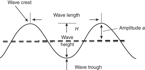
Figure 10.6 Surface wave motion.

Figure 10.7 Particle motion at various depths in water waves.
Ocean waves transport mechanical energy. The energy transported by a wave is directly proportional to the square of the amplitude of the wave.
The power across each metre of wave front associated with a wave of wavelength λ and height H is given by [7–9]
For irregular waves of height H (m) and period T (s), an equation for power per unit of wave front can be derived as
Therefore, the power in the wave increases directly as the square of the wave amplitude and directly as the period. Excluding waves created by major storms, the largest waves are about 15 m high and have a period of about 15 s. According to Eq. (10.8), such waves carry about 1700 kW of potential power across each metre of wave front.
10.7 Wave Energy Converters
The energy in sea waves can be converted into mechanical energy by using proper wave power mechanisms known as wave energy converters, wave devices or wave machines. There is a wide range of wave energy technologies. Each technology uses different solutions and devices to capture energy from waves. There are three main categories: oscillating water columns (OWCs) that use trapped air pockets in a water column to drive a turbine; oscillating body converters that are floating or submerged devices using the wave motion (up/down, forwards/backwards, side to side) to generate electricity; and overtopping converters that use reservoirs to create a head and subsequently drive turbines.
10.7.1 Oscillating Water Column
An OWC is a wave energy converting technology that can be installed onshore preferably on rocky shores; near shore in up to 10 m of water; or offshore in 40–80 m deep water OWC-type wave energy devices are employed for converting fluid power into rotary-mechanical power. In its simplest form, this consists of a partially immersed vertical tube. An OWC comprises two key elements: a collector chamber, which takes power from the waves and transfers it to the air within the chamber, and a power takeoff (PTO) system, which converts the pneumatic power into electricity or some other usable form. The most commonly used form of PTO in this application is the Wells turbine/induction generator combination. An OWC using a Wells turbine to convert wave energy to electrical energy is shown in Fig. 10.8. The motions of ocean/sea waves push an air pocket up and down behind a breakwater. Then the air passes through an air turbine. When a wave passes on to a partially submerged cavity open under the water (Fig. 10.8), it cause the column to act as a piston, moving up and down and thereby forcing the air out of the chamber and back into it. This continuous movement generates a reversing stream of high-velocity air, which is channelled through rotor blades driving an air turbine–generator group to produce electricity. When the waves rise, the air is forced up the chamber, increasing in speed. As the waves fall, air is sucked back into the chamber. A high-speed bidirectional airflow is therefore produced and is converted into unidirectional rotational motion using a Wells turbine. The doubly fed induction machine is the favoured machine for the OWC.

Figure 10.8 An oscillating water-column wave energy converter.
The problem with this pneumatic system is that the rushing air can be very noisy, unless a silencer is fitted to the turbine. But the noise is not a huge problem anyway, as the waves make lot of noise themselves.
Other forms of self-rectifying turbines, which are the impulse machines of Dresser-Rand and Oceanlinx, are also under development. The manufacturers claim that these machines offer a higher conversion efficiency compared to a Wells turbine, but there is no publically available information to demonstrate in real sea.
The main advantages of OWC devices are as follows:
- There are few moving parts, and there is no moving part inside water.
- It can be used for offshore, near-shore and shore-line locations.
- The air velocity can be increased by reducing the cross-sectional area of the air channel, so that high-speed turbines can be used.
10.7.2 Oscillating Body
Oscillating-body converters are either floating (usually) or submerged (sometimes fixed to the bottom). They exploit the more powerful wave regimes that normally occur in deep waters where the depth is greater than 40 m. In general, they are more complex than OWCs, particularly with regard to their PTO systems. The simplest oscillating-body device is the heaving buoy reacting against a fixed frame of reference. The rise and fall of the waves move the buoy-like structure, creating mechanical energy which is converted into electricity and transmitted to the shore by means of a secure, undersea transmission line.
In fact, the many different concepts and ways to transform the oscillating movement into electricity have given rise to various PTO systems, for example hydraulic generators with linear hydraulic actuators, linear electric generators and piston pumps. The advantages of oscillating-body converters include their size and versatility since most of them are floating devices.
10.7.3 Overtopping Converters (or Terminators)
Overtopping devices consist of a floating or bottom-fixed water reservoir structure. These devices use reflector arms and/or sloped surfaces to drive the waves to a reservoir of stored seawater. The potential energy, due to the height of the collected water above the sea surface, is transformed into electricity using conventional low-head hydro turbines.
As the waves hit the structure, they flow up a ramp and over the top (hence the name “overtopping”), into a raised water reservoir on the device in order to fill it. Wave energy is converted into potential energy by lifting the water up onto a higher level. As shown in Fig. 10.10, the captured potential energy of the trapped water in the reservoir is extracted using gravity as the water returns to the sea via a low-head Kaplan turbine generator located at the bottom of the wave capture device. An advantage for overtopping devices is that the low-head turbine technology used in hydropower can be applied here. These devices are often large installations and can be placed in shore line as well as offshore.
10.7.4 Point Absorbers and Attenuators
A large group of wave energy converters are based on directly converting the waves into an oscillating mechanical motion. The point absorber is a type of wave energy device that could potentially provide a large amount of power in a relatively small device, compared to other technologies. While there are several different designs and strategies for deploying these types of devices, they all work in essentially the same manner. Point absorbers are relatively small compared to wave length and may be bottom-mounted or floating structures. If these are floating structures, they absorb energy from all directions at or near the water surface. A point-absorber wave energy conversion system is shown in Fig. 10.9. Point-absorber devices can be designed to work at near-shore and offshore sites and at most sea states. A small (1–5 m diameter) and light (<5 tonnes) buoy such as the one used in the sea-based concept has high absorption for small and high waves. As waves become longer, absorption starts to drop. Heavy (100 s of tonnes) and big (10–25 m) point absorbers such as Wave bob are more suited to long waves (>7 s). A point absorber can be designed for short- or long-wave periods, and by using active control, a single point absorber can be designed to match most sea states. The diameter of a point absorber should be less than 1/6 of the wavelength; otherwise, it will start counteracting itself. For systems without control, absorption is usually 10–30%. Active control has shown absorption of 40–5% for specific wave climates (Fig. 10.10).

Figure 10.9 Point-absorber wave energy converter.

Figure 10.10 Overtopping device for wave energy conversion.
Source: Polinder and Scuotto (2005) [10]. Reproduced with permission from IEEE.
10.8 Power Takeoff Systems
The PTO system converts the captured mechanical energy of the wave into electrical energy. In both wave and tidal systems, a mechanical interface can be employed to convert the slow rotational speed or reciprocating motion into high-speed rotational motion for connection to a conventional rotary electrical generator (Fig. 10.11). Direct drive is also an option but is not in use. The PTO for wave energy can be classified as follows:
- 1. Air turbines for OWC
- 2. Hydraulic systems
- 3. Water turbines
- 4. Direct drive

Figure 10.11 Inverted pendulum.
10.8.1 Air Turbines for OWC
The energy conversion from the oscillating air column can be achieved by using Wells turbine which was introduced by Dr A. A. Wells in 1976 because of its ability to rotate in the same direction, irrespective of the airflow direction. Furthermore, this turbine is one of the simplest and probably the most economical turbines for wave energy conversion. However, according to a previous studies, Wells turbine has inherent disadvantages: low efficiency about 60–65% at high flow coefficient and poor starting characteristics in comparison with conventional turbines because of a severe stall. It is possible to use pitch control of the turbine blades to increase efficiency.
Recently, in order to develop a high-performance self-rectifying air turbine for wave energy conversion, an impulse turbine for bidirectional flow has been proposed. Its rotor is basically identical to the rotor of a conventional single-stage steam turbine of axial-flow impulse type. Since the turbine is required to be self-rectifying, instead of a single row of guide vanes (as in the conventional de Laval turbine), there are two rows, placed symmetrically on both sides of the rotor. These two rows of guide vanes are as the mirror image of each other with respect to a plane through the rotor disc.
10.8.2 Hydraulic Systems
Another method of converting the low-speed oscillating motion of the primary WEC interface is to employ a hydraulic system. Axial-flow reaction turbines are used to convert the head (typically 3–4 m at full size) created between the reservoir of an overtopping device and the mean sea level. Figure 10.12 shows a basic hydraulic PTO system with energy storage for a WEC. Components of a basic compression unit include a hydraulic cylinder, two pressure accumulators and a valve-control system. The hydraulic cylinder is used to transfer the motion of the floating body into a double-acting piston in the cylinder connected to it. Two chambers are connected respectively to a high-pressure accumulator and to a low-pressure accumulator. The motion of the cylinder results in varied pressure difference that results in a torque on the generator/motor. The flow may be controlled by adjustable inlet guide vanes. In some cases, the blades of the runner can also be adjusted (Kaplan turbines) which greatly improves efficiency over a wide range of flows; however, this can be costly and is not normally employed in the small turbines.
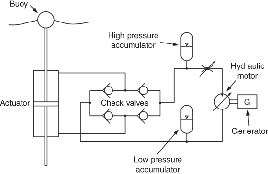
Figure 10.12 Typical hydraulic PTO with energy storage.
Hydraulic systems are efficient energy conversion systems consisting of two energy conversion systems. Accumulators are included in the circuit to provide energy storage and to maintain constant flow to the hydraulic motor. In addition, the low-pressure accumulator provides a small boost pressure to reduce the risk of cavitation. These hydraulic turbines may reach peak efficiencies of about 90%. Their efficiency is in general quite sensitive to the head-to-rotational-speed ratio, which makes the use of variable-speed electrical generators highly advantageous, especially in the case of Pelton turbines.
10.8.3 Water Turbines
Water turbines used in run of river power plants have been proposed for so-called overtopping devices, which are essentially low-head hydro systems. The principle of operation of such devices is that water during high tide is stored and has potential energy which is used by the water turbines to convert it into mechanical energy.
Waves crash over the device into a floating reservoir, which in turn feeds a water turbine coupled to conventional rotary generators.
10.8.4 Direct Drive
Wave power devices traditionally use conventional rotary electrical machines for power conversion. However, hydraulic systems or air turbines are required to convert the low reciprocating motion of the wave device to rotation at 1500 rpm. The concept of a direct drive system is introduced, in which a reciprocating electrical machine is driven at the same speed as the device. In a direct drive system, there is no mechanical interface coupling the device to the electrical generator. Hence, it has the potential to provide a simpler system requiring fewer moving parts, lower maintenance requirements and higher efficiency.
The direct drive system employs a linear generator which consists of a magnetic translator that is driven to reciprocate synchronously with the motion of a directly coupled buoy/floating body. A simplified structure of direct-drive conversion system is shown in Fig. 10.13.

Figure 10.13 Direct drive.
Since the generator and prime mover are connected without any gear, the velocity of the generator is equal to that of the prime mover, being of the order of 0.5–2 m/s. In order to generate sufficient amount of power, the machine will have to exert large forces. Direct drive machines are physically very large and heavy. The concept of direct drive has been demonstrated within the Archimedes Wave Swing (AWS) device. Figure 10.14 shows the principle of operation of the device. The device is seabed-mounted. It consists of an air-filled chamber with a floater that moves down with the crest of a wave and up with a floater that moves down with the crest of a wave and up with the trough of a wave. It is a submerged offshore device activated by the fluctuations of static pressure caused by the surface waves, thus exploiting only their potential energy. Basically, the AWS is an air-filled cylindrical steel chamber whose lid, called the floater, is a heaving body while the bottom part is fixed. The active force that moves the floater is supplied by the pressure difference acting on its top. When the wave crest is above the AWS, the chamber volume is reduced by the high water pressure. When the trough is above, the floater heaves under the action of the chamber pressure. The air within the chamber behaves as a spring whose stiffness can be adjusted by pumping water in or out of the chamber (chamber volume changes). In the AWS, direct-drive energy conversion takes place via a permanent magnet (PM) linear synchronous generator. This type of energy conversion does not allow energy storage. As a consequence, the output power exhibits poor quality (Fig. 10.15).

Figure 10.14 Archimedes Wave Swing.
Source: Polinder and Scuotto (2005) [10]. Reproduced with permission from IEEE.

Figure 10.15 (a) Direct-force and (b) inertial-force generators.
10.9 Piezoelectric Generators
Sea wave energy harvesting with piezoelectric materials can be classified into three main categories: the vortex caused by the bluff body fixed on the seabed; the vibration of heaving-based buoy on the sea surface; and the vibration of the foam cantilever substrate attached by polymer patches to absorb the small wave motion near the seabed.
The vast majority of piezoelectric energy harvesting devices use a cantilever beam structure [11]. Basically, the harvester beam is located on a vibrating host structure, and the dynamic strain induced in the piezoceramic layer(s) generates an alternating voltage output across the electrodes covering the piezoceramic layer(s). This voltage can be extracted through electrical equipment connected to the electrodes. A common piezoelectric generator is illustrated in Fig. 10.16, where a cantilever beam, with a mass attached to its tip, will oscillate and develop bending stresses along the beam. It is clearly seen that the transverse motions of the water particles have no effect on the bending of the cantilever, and only the longitudinal waves are responsible for producing energy.

Figure 10.16 Common piezoelectric-based power generator.
The electrical-circuit analogue representing such systems is shown in Fig. 10.17. It is composed of a mechanical section, an electrical section and a transformer. In the mechanical part of the circuit, the inductor, the resistor and the equivalent capacitor represent the equivalent mass of the system, the mechanical damping and the mechanical stiffness, respectively. The stress generator represents the stresses induced by input vibrations and is analogous to a voltage source. In the electrical section, the capacitor represents the actual electrical capacitance of the piezoelectric bender.

Figure 10.17 Electrical circuit diagram.
A cantilever beam can have many different modes of vibration, each with a different resonant frequency. The first mode of vibration has the lowest resonant frequency and typically provides the most deflection and therefore electrical energy. A lower resonant frequency is also closer in frequency to physical vibration sources, and generally more power is produced at lower frequencies. Therefore, energy harvesters are generally designed to operate in the first resonant mode [12, 13].
10.9.1 Power Extraction Systems
The piezoelectric generator, behaving as a resonator, acts as a sinusoidal voltage source. When it is implemented in the ocean, the generated AC current has to be processed and rectified for proper usage, before storing the energy in a battery or supplying it directly to a load. The controller regulates the output voltage depending on the need of the specific application. The external circuit connected to the piezoelectric harvester has a great influence on the energy flow in the harvester [13].
10.10 Ocean Thermal Energy Conversion
Ocean thermal energy conversion (OTEC) generates electricity by harnessing the temperature difference between the warm surface of tropical oceans and the colder deep waters. The surface of ocean retains the solar radiation in tropical regions, resulting in average year-round surface temperatures of about 28 °C. The warm water layer of the sea extends to depths of about 100–200 m. There is a temperature difference of 10–25 °C, between this warm surface and cold water in about 1000 m depth. The equatorial and tropical regions have higher difference in temperature than other regions. Heat engines can generate power based on thermodynamic principle of heat transfer from a temperature difference of about 20°C. The disadvantage of OTEC is that it requires large pipelines and heat exchangers to produce relatively modest amounts of electricity, making it very expensive. In order to handle such a large amount of water flow, the heat exchangers of an OTEC plant will have to be very large. Early estimates of the total heat exchanger surface area ranged from 7 to 9 m2/kW of electrical capacity. These high fixed costs dominate the economics of OTEC to the extent that it cannot compete with conventional power systems, except in limited niche markets.
From thermodynamics, it is known that the maximum efficiency of heat engines (Carnot cycle) is given by –

where ![]() and
and ![]() are low and high temperatures measured in kelvin.
are low and high temperatures measured in kelvin.
For example, if the warm surface layer temperature is 298 K (25 °C) and the cold temperature is 278 K (5 °C), then
In practice, the thermal efficiency of a practical system may be only 2–4% when energy required in pumping cold water and losses are included. Thus, large amount of water is required to produce sufficient electricity.
10.10.1 Technology for OTEC
OTEC technology is not new. In 1881, Jacques Arsene d'Arsonval, a French physicist, proposed for the first time utilization of thermal energy of the ocean. His student Georges Claude, in 1930, built the first OTEC plant in Cuba. The system produced 22 kW of electricity with a low-pressure turbine. In 1935, Claude constructed another plant aboard a 10,000-ton cargo vessel moored off the coast of Brazil. In 1956, French scientists designed another 3-mW OTEC plant for Abidjan, Ivory Coast, West Africa. The plant was not completed, because it was too expensive. OTEC power systems operate as cyclic heat engines based on Rankine cycle. As shown in Section 1.5.5, the complete conversion of thermal energy into electricity is not possible. A portion of the heat extracted from the warm seawater must be rejected to a colder thermal sink. The thermal sink employed by OTEC systems is seawater drawn from the ocean depths by means of a submerged pipeline.
There are three kinds of OTEC systems: closed-cycle, open-cycle and hybrid [14].
10.10.1.1 Closed-Cycle
Closed-cycle systems use fluids with low boiling point such as ammonia, freon or propane which are evaporated using warm surface water. The vapour is then used to rotate a turbine to generate electricity. Warm surface seawater is pumped through a heat exchanger, where the low-boiling-point fluid is vaporized. The expanding vapour turns the turbo generator. The vapour drives a generator that produces electricity; the working fluid vapour is then condensed by the cold water taken from deep ocean and pumped back in a closed system. Figure 10.18 shows a simplified schematic diagram of a closed-cycle OTEC system. The principal components are the heat exchangers, turbo generator and seawater supply system. These components account for most of the local power consumption and a significant fraction of the capital cost. In this system, heat transfer from warm surface seawater occurs in the evaporator, producing a saturated vapour from the working fluid. Electricity is generated when this gas expands to lower pressure through the turbine. Latent heat is transferred from the vapour to the cold seawater in the condenser, and the resulting liquid is pressurized with a pump to repeat the cycle. It is best suited to areas near the equator, where the intense solar radiation produces sufficiently warm surface water.

Figure 10.18 Closed cycle.
Most suitable working fluids for closed-cycle OTEC applications are ammonia and various refrigerants. Their primary disadvantage is the environmental hazard posed by leakage; ammonia is toxic in moderate concentrations, and many refrigerants have been banned. The Kalina cycle is a variant of the OTEC closed cycle. Whereas simple closed-cycle OTEC systems use a pure working fluid, the Kalina cycle proposes to employ a mixture of ammonia and water with varying proportions at different points in the system (Fig. 10.19).

Figure 10.19 Kalina cycle.
10.10.1.2 Open-Cycle
Open-cycle systems use the tropical oceans' warm surface water to make electricity.
The open cycle consists of the following steps: (i) warm seawater is placed in a low-pressure container for flash evaporation; (ii) expansion of the vapour is used to drive a turbine to generate power; (iii) heat transfer to the cold seawater thermal sink resulting in condensation of the working fluid; and (iv) compression of the non-condensable gases (air released from the seawater streams at the low operating pressure) to pressures required to discharge them from the system.
The steam, which has left its salt behind in the low-pressure container, is almost pure, freshwater. Only less than 0.5% of the mass of warm seawater entering the evaporator is converted into steam. Thus, an open-cycle OTEC plant can provide a large quantity of desalinated water.
The name “open cycle” comes from the fact that the working fluid (steam) is discharged after a single pass and has different initial and final thermodynamic states; hence, the flow path and process are “open”. The essential features of an open-cycle OTEC system are presented in Fig. 10.20. Warmer surface water is introduced through a valve in a low-pressure compartment and flash evaporated. The vapour drives a generator and is condensed by the cold seawater pumped up from below. The condensed water can be collected and, because it is freshwater, used for various purposes. Additionally, the cold seawater pumped up from below, after being used to facilitate condensation, can be introduced in an air-conditioning system, Furthermore, the cold water can potentially be used for aquaculture purposes, as the seawater from the deeper regions close to the seabed contains various nutrients, such as nitrogen and phosphates.

Figure 10.20 Open cycle.
The entire system, from evaporator to condenser, operates at partial vacuum, typically at 1–3% of atmospheric pressure. Vacuum compressor is used for initial evacuation of the system and removal of non-condensable gases during operation. Effluent from the condenser must be discharged to the environment. Liquids are pressurized to ambient levels at the point of release by means of a pump or, if the elevation of the condenser is suitably high, can be compressed hydrostatically.
10.10.1.3 Hybrid Systems
Hybrid cycles combine the potable water production capabilities of open-cycle OTEC with the potential for large electricity generation capacities offered by the closed cycle. Several hybrid-cycle variants have been proposed. A hybrid system is shown in Fig. 10.21. In a hybrid system, warm seawater enters a vacuum chamber, where it is flash-evaporated into steam, similarly to the open-cycle evaporation process. This produces freshwater. The steam vaporizes a low-boiling-point fluid, usually ammonia (in a closed-cycle loop) that drives a turbine to produce electricity. Subsequently, the warm seawater discharged from the closed-cycled OTEC is flash-evaporated similarly to an open-cycle OTEC system and cooled with the cold water discharge. This produces freshwater. All three types of OTEC can be land-based, sea-based or based on floating.

Figure 10.21 Hybrid cycle.
Another advantage of the hybrid cycle related to freshwater production is that condensation occurs at significantly higher pressures than in an open-cycle OTEC condenser, due to the elimination of the turbine from the steam flow path. This may, in turn, yield some savings in the amount of power consumed to compress and discharge the non-condensable gases from the system.
10.11 Summary
In this chapter, it is shown that the energy potential in tides is very high. The ocean can produce two types of energy: thermal energy from the Sun's heat and mechanical energy from the tides and waves. A barrage (dam) is typically used to convert tidal energy into electricity by forcing the water through turbines, activating a generator. For wave energy conversion, there are three basic systems: channel systems that funnel the waves into reservoirs; float systems that drive hydraulic pumps; and OWC systems. All these systems are described in this chapter.
In addition, ocean thermal energy which is used for many applications, including electricity generation, is also discussed in this chapter. There are three types of electricity conversion systems: closed-cycle, open-cycle and hybrid. Closed-cycle systems use the ocean's warm surface water to vaporize a working fluid, which has a low boiling point, such as ammonia; all these systems are discussed.
References
- 1 Seymor, R.J. (1992) Ocean Energy Recovery: The state of art, ASCE Publications.
- 2 Charlier, R.H. and Finkl, C.W. (2009) Ocean Energy Tide and Tidal power, Springer.
- 3 Hardisty, J. (2014) Wave and Tidal Research Review, 2nd edn, Hull University.
- 4 Gorlov, A. M. (1979) Some new conceptions in the approach to harnessing tidal energy, Proc. Miami Int. Natinal conf. Alt energy sources.
- 5 Dunlap, R.A. (2015) Sustainable Energy, Cengage Learning.
- 6 Charlier, R.H. (1982) Tidal Energy, Van Nostrand Reinhold, New York.
- 7 Benelghali, S. et al. (2010) Marine Tidal Current Electric Power Generation Technology: State of the Art and Current Status, HAL archives.
- 8 Peppas, L. (2008) Ocean, Tidal, and Wave Energy: Power from the Sea (Energy Revolution), Prime Publishing.
- 9 Chris, G. and Patrick, C. (2005) The power potential of tidal currents in channels. Proc of the Royal Society.
- 10 Polinder, H. and Scuotto, M. (2005) Wave energy converters and their impact on power systems, International conference on future power systems, pp. 9
- 11 Jbaily, A. and Yeung, R.W. (2015) Piezoelectric devices for ocean energy: a brief survey. Journal of Ocean Engineering and Marine Energy, 1, 101.
- 12 Wang, D.A. and Ko, H.H. (2010) Piezoelectric energy harvesting from flow induced vibration. J Micromech Microeng, 20 (2), 025019.
- 13 Shu, Y.C. and Lien, I.C. (2006) Analysis of power output for piezoelectric energy harvesting systems. Smart Materials and Structures, 16, 1499.
- 14 Kempener, R. and Neumann, F. (2014) Ocean thermal energy Conversion Technology brief IRENA Ocean energy Technology brief 1.