
Chapter 13
Control of Grid-Connected Photovoltaic and Wind Energy Systems
13.1 Introduction
In many countries, the renewable generation from wind and solar has increased substantially during the past few years and forms a significant proportion of the total generation in the grid. At present, this renewable generation is concentrated in few areas, which is quite significant. It therefore requires serious consideration to balance the variability of such generation. With further increase in renewable generation, it is quite clear that some changes may be necessary in the operation of grid for large-scale integration of such variable renewable energy sources (RESs), although the demand for electricity, or load, also varies with time, but because it is slow or small, the power system is designed to handle that uncertainty. The short-term changes in load (over seconds or minutes) are generally small and caused by random events that change the demand in different directions. Over longer periods (several hours), changes in load tend to be more predictable. For example, there is a daily pattern of morning and evening load pattern highly correlated with human endeavours. The main difference is that load variations are more predictable than wind and solar variations. In order to maintain a constant frequency, the generation and load must be matched at every instant. The problem arises when there is mismatch between power supply and demand.
But all the generation from RES is not unpredictable. For example, the electricity production of an individual wind turbine is highly variable, but the aggregate variation of multiple turbines at a single site is less and can be easily monitored. The aggregation of multiple wind generation sites over a large geographic area results in even less variations. Having large number of turbines in many locations results in less variability and enhanced prediction. Variability of generation is also function of time. The variability of large-scale wind power over seconds or minutes is generally small. However, for several hours, it can be large.
Similarly, some aspects of variation in solar energy availability are also predictable (e.g. sunrise and sunset). Other aspects, such as intermittent cloud cover, cannot be predicted. However, the same reduction in variability is observed for the aggregation of solar photovoltaic (PV) plants over a broad geographic area [1, 2]. In this chapter, only the PV system and wind energy sources connected to grid and their control are discussed.
13.2 Operation and Control of Grid-Connected PV System
In general, PV cells can be connected to the grid (grid connection application), or they can be used as isolated power supplies. In isolated applications, PV panels supply local loads which can be residential or commercial. An electrical power generating system that uses a PV array as the primary source of electricity generation and is intended to operate synchronously and in parallel with the electric utility network is known as a grid-connected PV system. About 75% of the total PV systems installed in the world are connected to grid. All PV systems are connected to the utility grid through a voltage-source inverter (VSI) and a boost converter.
Each grid-connected PV system has to perform two functions:
- Extract maximum power output from the PV array(s)
- Supply harmonic-free ac current into the grid
There are numerous ways of injecting synchronized power from PV modules into the utility grid. In each of these approaches, the MPPT and inverters are implemented with different techniques.
Such systems may also include battery storage, other generating sources and may operate on site loads independent of the utility network during outages (isolated mode). Two types of grid-connected PV systems are considered here [3]. These are
- 1. single-phase grid-connected PV systems and
- 2. three-phase grid-connected PV systems
13.2.1 Control of Single-Phase PV System
For residential applications, single-phase systems are commonly used. A new research trend in the residential generation system is to employ the PV parallel-connected configuration rather than the series-connected configuration to satisfy the safety requirements and to make full use of the PV generated power. For residential applications, typically, the power ratings range from 3 to 10 kW, and thus, a dc/dc converter is necessary to boost the dc voltage level within an allowable range for the PV inverter.
Figure 13.1 shows the block diagram of a PV system, and Fig. 13.2 shows the configuration of the grid-connected PV system for single-phase inverter connected by a dc/dc Boost converter and cascaded with a dc/ac inverter. The dc/dc boost converter performs MPPT for maximizing the output power of PV array to fully utilize the PV power and voltage boost to match that of grid inverter. The boost converter controls the PV array operating point by the switch duty command. The single-phase inverter controls the dc-link capacitor voltage and controls the output current to be in phase with the grid voltage. Then a single-phase buck dc/ac inverter is used to step down and to modulate the output voltage according to the grid voltage.

Figure 13.1 Block diagram of grid-connected PV system.

Figure 13.2 Grid-connected PV system.
Inverter-interfacing PV module(s) with the grid involves two major tasks. One is to ensure that the PV module(s) is operated at the maximum power point (MPP). The other is to inject a sinusoidal current into the grid. Since the inverter is connected to the grid, the standards given by the utility companies must be obeyed. During grid-connected mode, grid controls the amplitude and frequency of the PV inverter output voltage, and the inverter operates in a current-controlled mode. The current controller for grid-connected mode fulfils two requirements – (i) during light load condition, the excess energy generated from the PV inverter is fed to the grid; and (ii) during an overload condition or in case of unfavourable atmospheric conditions, the load demand is met by both PV inverter and the grid. On the other hand, during isolated grid operation, the PV inverter operates in voltage-controlled mode to maintain constant amplitude and frequency of the voltage across the load.
13.2.1.1 Control of PV-Side dc/dc Converter
The objective of PV-side controller is to extract the maximum power from the input source considering ambient temperature and solar irradiance. In general, the protection of the dc/dc converter (boost converter) should also be taken into consideration in this controller. The dc-dc boost converter stage could step up the input dc voltage to a required voltage value, which is the next input of the inverter. This stage also provides voltage regulation control on the intermediate dc bus that is not available at the source terminals, which can regulate the dc voltage into the required value. Perturb and Observe method is applied for maximum power tracking. This algorithm is mostly used, due to its ease of implementation. It is based on the following criterion: if the operating voltage of the PV array is perturbed in a given direction and if the power drawn from the PV array increases, this means that the operating point has moved towards the MPP, and therefore, the operating voltage must be further perturbed in the same direction. Otherwise, if the power drawn from the PV array decreases, the operating point has moved away from the MPP, and therefore, the direction of the operating voltage perturbation must be reversed.
The dc/dc controller comprises a three-level, nested-loop structure. The MPP controller forms the outer loop and generates the voltage set point for the voltage controller. The voltage loop is used to control the input capacitor voltage of the boost converter. The voltage loop generates a current set point for the inner current loop. This current regulator is used to regulate the inductor current. The output of the current loop is used to derive the duty cycle for the boost converter.
13.2.1.2 Control of Grid-Side Inverter
The output of the boost converter is connected to the dc side of a single-phase VSI via a dc-link capacitor. The grid converter performs the following tasks:
- Control of active power generated to the grid
- Control of reactive power transfer between PVF system and the grid
- Control of dc-link voltage
- Ensure high quality of the injected power
- Grid synchronization
The VSI is regulated by a nested control scheme with an outer voltage loop and an inner current loop. Usually, there is a fast internal current loop, which regulates the grid current, and an external voltage loop, which controls the dc-link voltage and maintains the voltage at the desired level. In synchronous reference frame control, also called dq control, reference frame transformation module, for example, abc → dq is used. It transforms grid current and voltage waveforms into a reference frame that rotates synchronously with the grid voltage. The synchronous frame regulator reduces the complexity by transforming the ac system to an equivalent dc system and then implementing proportional integral (PI) controllers for the d- and q-axis, respectively. In single-phase systems, unlike three-phase systems, not enough information is available to directly convert the ac current into the synchronous frame. In order to create the additional orthogonal-phase information from the single-phase inverter signal, two approaches can be adopted in order to create the additional phase-shifted state variables. These are as follows:
- Differentiating the inverter output voltage and inductor current. This is done by differentiating the measured real component to build another stationary orthogonal component. However, this method is very sensitive to noise. The inverter real-phase output waveform contains harmonics in addition to the fundamental component. Differentiation process thus does not yield a purely orthogonal component.
- Fictive axis emulation: To concurrently generate the required orthogonal current, fictive model of the system, which is the transfer function of the real system in a SRF, hereinafter called the fictive axis emulation can be used. The detailed structural diagram of the FAE is represented in Fig. 13.3. The grid current is assumed to be in line with the α-axis, and the β-axis currents are emulated using the FAE. The measured α and derived β currents are transformed into the dq axis and fed into the synchronous frame regulator. The angle used for the transformation is generated by a phase-locked loop (PLL). The synchronous frame regulator calculates a desired αβ voltage vector set point. This vector is scaled by the peak grid voltage amplitude to generate the modulation index for the modulator. The modulation indices are used to generate the switching signals for the VSI using a unipolar modulator.

Figure 13.3 dq control.
13.2.1.3 Inner Current Loop
The inverter is required to inject a sinusoidal grid current with low THD and in phase with the grid voltage. Thus, the output of the dc link voltage controller, which represents the reference grid current amplitude, is multiplied by a sinusoidal template obtained using a PLL synchronized with the utility voltage. The current controller attempts to match the grid current with this reference sinusoidal current. The most common types of current controllers are the PI with feed-forward controller and the proportional resonant (PR) controller. However, PR controllers have the ability to remove both the current's magnitude and phase steady-state errors without the need of voltage feed-forward unlike the conventional PI controller. Further, applying a Park transformation (![]() ) leads to the possibility of PI controllers to regulate the injected current, and afterwards, the modulation reference can be obtained by means of the inverse Park transformation (
) leads to the possibility of PI controllers to regulate the injected current, and afterwards, the modulation reference can be obtained by means of the inverse Park transformation (![]() ). Since the current control loop is responsible for the power quality, it will also be effective and valid in the design of current controllers and the LCL filter. By introducing harmonic compensators (HCs) for the controller and adding passive damping for the filter, an enhancement of the current controller tracking performance can be achieved and the background distortion influence is alleviated.
). Since the current control loop is responsible for the power quality, it will also be effective and valid in the design of current controllers and the LCL filter. By introducing harmonic compensators (HCs) for the controller and adding passive damping for the filter, an enhancement of the current controller tracking performance can be achieved and the background distortion influence is alleviated.
13.3 Grid Synchronization
The main aspect of connection to the grid by power converter is that the magnitude and phase angle of fundamental frequency component of injected current should synchronize with the grid voltage. Different methods to extract the phase angle have been developed based on grid requirements, and comparative studies of some of them have been carried out. A brief description of the main methods is as follows:
- Zero-Crossing Method, Simplest synchronization solution is the filtered zero-crossing detection (ZCD) method where the zero-crossing point is detected every one period and the sin-table pointer is reset from zero scratch. However, due to the poor performances mainly when grid voltages register variations such as harmonics, it is not the optimal synchronization method.
PLL technique has been the state-of-the-art method to detect the phase angle of the grid voltage. This algorithm has a better rejection of grid harmonics, notches and any other kind of disturbances. However, for single-phase applications, creation of the orthogonal signal generator system is required. The block diagram of PLL is shown in Fig. 13.4. In this technique, for the synchronization of time-varying signal, the difference between phase angle of the input and that of the output signal is measured by phase detection. It is then passed through the loop filter, the output of which drives the voltage-controlled oscillator. The VCO generates the output which follows the input signal.

Figure 13.4 Phase-locked loop.
For single-phase system, PLL based on T/4 delay can be employed for synchronization. When the fundamental grid frequency time period is T, using first-in-first-out (FIFO) buffer, the T/4 transport delay technique can be implemented, by setting its size to one-fourth of the number of samples contained in one cycle of the fundamental frequency. In this method, the orthogonal signal output will be perfect only if the grid frequency does not change; otherwise, this will result in errors in synchronization. In additon, it does not have filtering capability to remove the harmonic components in the input signal.
Robust Single-Phase PLL: By using robust PLL technique, the phase, frequency and amplitude information of single-phase signals can be estimated instantly even in frequency variation and harmonic distortion. It consists of two-phase signal generator which produces ![]() and
and ![]() , a vector rotator, a phase synchronizer, a lowpass filter and a multirate sample holder. This method has the following attractive features: (i) the estimation system results in a nonlinear system, but it can be stabilized; (ii) all sub-systems constructing the system can be easily designed; (iii) “two-phase signal generator” can auto-tune a single system parameter in response to varying frequency of the injected signal; (vi) high-order “PLL Controllers” allowing fast tracking can be stably used; and (v) even in hostile envelopments, favourable instant estimates can be obtained.
, a vector rotator, a phase synchronizer, a lowpass filter and a multirate sample holder. This method has the following attractive features: (i) the estimation system results in a nonlinear system, but it can be stabilized; (ii) all sub-systems constructing the system can be easily designed; (iii) “two-phase signal generator” can auto-tune a single system parameter in response to varying frequency of the injected signal; (vi) high-order “PLL Controllers” allowing fast tracking can be stably used; and (v) even in hostile envelopments, favourable instant estimates can be obtained.
13.4 Control of Three-Phase Grid-Connected PV system
Three-phase grid-connected utility-scale systems can have tens of megawatts of power output under optimum conditions of solar irradiation. These systems are usually ground-mounted and span a large area for power harvesting.
Figure 13.5 shows the block diagram of a three-phase PV system with power feed-in functions. The output of PV array is connected to a boost dc converter that is used to increase the array terminal voltage to a higher value so it can be interfaced to the distribution system grid at 6.6 kV. The dc converter controller also performs the MPPT function. A dc-link capacitor is used after the dc converter and acts as a temporary power storage device to provide the VSI with a steady flow of power. The capacitor's voltage is regulated using a dc-link controller that balances the input and output powers of the capacitor. The VSI is controlled in the rotating dq frame to inject a controllable three-phase ac similarly to single-phase system [4]. A PLL is used to lock on the grid frequency and provide a stable reference synchronization signal for the inverter control system, which works to minimize the error between the actual injected current and the reference current obtained from the dc-link controller. An LC low-pass filter is connected at the output of the inverter to attenuate high-frequency harmonics and prevent them from propagating into the power system grid. A second-order LCL filter is obtained if the leakage inductance of the interfacing transformer is referred to the low voltage side. This provides a smooth output current with low harmonics.

Figure 13.5 Block diagram of three-phase PV system connected to grid.
13.5 Selection of Inverter for PV System
Inverters currently available are typically rated for the following:
- Maximum dc input power, that is, the size of the array in peak watts
- Maximum dc input current
- Maximum specified output power, that is, the ac power output supplied to grid
The inverters must also be able to detect an islanding situation and take appropriate measures in order to protect persons and equipment. Islanding is the continued operation of the inverter when the grid has been removed on purpose, by accident or by a fault. When grid supply is not available, the PV system has to supply the local load.
The inverter may simply fix the voltage at which the array operates or (more commonly) use a MPP tracking function to identify the best operating voltage for the array [4, 5]. The inverter operates in phase with the grid (unity power factor) and generally delivers as much power as it can generate at a particular time to the electric power grid.
13.5.1 Central Inverters
The earlier PV systems were based on technology, which used centralized inverters that interfaced a large number of PV modules to the grid as shown in Fig. 13.6. The PV modules were divided into series connections (called a string), so that sufficient voltage can be generated to avoid further amplification. These series connections were then connected in parallel, through string diodes, in order to reach high power levels. Typically, centralized inverter handles all tasks by itself such as MPPT (usually by the microcontroller), grid current control and voltage amplification also if required. The inverter must be designed to handle a peak power of twice the nominal power.

Figure 13.6 Centralized inverter.
These inverters are characterized by high efficiency and lower cost. However, they have some severe limitations, such as high-voltage dc cables between the PV modules and the inverter, power losses due to a centralized MPPT, power losses due to mismatch in the PV modules, losses in the string diodes. In addition, the reliability of the plant is limited due to the dependence of power generation on a single inverter. Centralized configuration is mainly used in PV plants that have nominal power higher than 10 kW. Thus, the central inverters are mainly three-phase inverters.
13.5.2 String Inverter
For small domestic applications in the range of 0.5–1 kW, string inverters are most suitable. The string inverter, shown in Fig. 13.7, is a reduced version of the centralized inverter, where a single string of PV modules is connected to the inverter called string inverter. They are based on a modular concept, where PV strings, made up of series-connected solar panels, are connected to separate inverters. The string inverters are paralleled and connected to the grid. The input voltage may be high enough to avoid voltage amplification. This requires roughly 15–16 PV modules in series with one inverter per string. The total open-circuit voltage for 16 PV modules may reach as high as 720 V. Fewer PV panels can also be used, but then a dc-dc converter or a line-frequency transformer is needed for a boosting stage. The advantages compared to the central inverter are as follows:
- There are no losses associated with the string diodes as no string diode is necessary.
- Separate MPPT can be used for each string.

Figure 13.7 String inverter.
13.5.3 ac Module Inverter
In a module inverter, one inverter is used for each module. An ac module is made up of a single solar panel connected to the grid through its own inverter, as shown in Fig. 13.8. The advantage of this configuration is that there are no mismatch losses, due to the fact that every single solar panel has its own inverter and MPPT, thus maximizing the power production. The power extraction is much better optimized than in the case of string inverters. One other advantage is the modular structure, which simplifies the modification of the whole system because of its “plug and play” characteristic. One disadvantage is the low overall efficiency due to the high-voltage amplification, and the price per watt is still higher than in the previous cases. But this can in the future maybe be overcome by mass production.

Figure 13.8 Module inverter.
13.5.4 Multi-String Inverters
Multi-string inverter shown in Fig. 13.9 is an intermediate solution between string inverters and module inverters. A multi-string inverter combines the advantages of both string and module inverters, by having many dc-dc converters with individual MPPTs, which feed energy into a common dc-ac inverter. Here each PV module or string is connected to a dedicated dc-dc converter that is connected to a common dc-ac inverter. In this case, the task for each dc/dc converter is MPPT and, normally, the increase of the dc voltage. The dc/dc converters are connected to the dc link of a common dc/ac inverter, which takes care of the grid-current control. This is beneficial since a better control of each PV module/string is achieved, and that common dc/ac inverter may be based on a standard variable-speed drive technology.

Figure 13.9 Multi-string inverter.
The main features of the multi-string technology are as follows:
- Optimum energy yield
- Optimum monitoring of strings
- Low specific costs of PV converter
- Minimum costs of PV system installation
- Nominal power of converter unit not limited
- Modular extendibility
13.6 Power Decoupling
The power fluctuations between dc and ac grid for single-phase inverters has to be decoupled by energy storage. Power decoupling is normally achieved by means of an electrolytic capacitor forming a dc link. Because to minimize the ac side of the inverter switching frequency, dc-link capacitor is essential. A very simple solution to mitigate its negative impact is to use bulky electrolytic capacitors in the dc link so that they can act as buffers to the ac-side ripple power. However, those electrolytic capacitors are known to have high equivalent series resistance (ESR) and low ripple current capability, and their lifetime is also relatively short (several thousand hours) when stressed with the nominal voltage and the ripple current. Thus, it should be kept as small as possible and preferably substituted with film capacitors. The capacitor is placed either in parallel with the PV modules or in the dc link between the inverter stages in multi-link inverter.
Recently, some active power decoupling methods have been proposed to cope with this problem, and the fundamental principle behind them is to introduce an extra active circuit in the system, so that the ripple power can be shifted away from the dc link and stored by other components with expanded lifetime, for example, inductors and film capacitors, in a more efficient and effective way.
13.7 Isolation Between Input and Output
Conventionally, a classification of PV topologies is divided into two major categories: PV inverters with dc/dc converter (with or without isolation) and PV inverters without dc/dc converter (with or without isolation). Galvanic isolation can be either on the dc side in the form of a high-frequency dc-dc transformer or on the grid side in the form of a big bulky ac transformer. Both of these solutions offer the safety and advantage of galvanic isolation, but the efficiency of the whole system is decreased due to power losses in these extra components. The most important advantages of transformerless PV systems can be observed in higher efficiency and smaller size and weight compared to a system with transformers. However, the resulting galvanic connection between the grid and PV array introduces ground leakage current path due to the effect of solar panel parasitic capacitance, for example, 10–100 nFd to the PV systems that have galvanic isolation (on either the dc side or the ac side).
One disadvantage of transformerless systems is that the missing line-frequency transformer can lead to dc currents in the injected ac current by the inverter, which can saturate the core of the magnetic components in the distribution transformer, which may lead to overheating.
13.8 Transformers and Interconnections
Grid-connected PV systems, particularly low-power single-phase systems (up to 5 kW), are becoming more popular worldwide. Issues such as reliability, high efficiency, small size and weight and low price are of great importance to the conversion stage of the PV system. Quite often, these grid-connected PV systems include a line transformer in the power-conversion stage, which guarantees galvanic isolation between the grid and the PV system, thus providing personal protection. Furthermore, it strongly reduces the leakage currents between the PV system and the ground. However, now it is possible to implement both ground-fault detection systems and solutions to avoid injecting dc current into the grid within the inverters.
The transformer can then be eliminated without impacting system characteristics related to personal safety and grid integration [1, 5–8]. In addition, the use of a string of PV modules allows MPP voltages large enough to avoid boosting voltages in the conversion stage. This conversion stage can then consist of a simple buck inverter, with no need of a transformer or boost dc-dc converter, and it is simpler and more efficient. But if no boost dc-dc converter is used, the power fluctuation causes a voltage ripple in the PV side at double the line frequency. This in turn causes a small reduction in the average power generated by the PV arrays due to the variations around the MPP.
The efficiency drop is 2% more if line-frequency transformer is used instead of high-frequency transformer. Hence, when grid isolation is mandatory, the incorporation of a high-frequency transformer is preferred. This implies the need for a dc-dc converter in the structure of the PV power system. A grid-connected inverter with high-frequency link of a PV system is shown in Fig. 13.10. The high-frequency inverter converts dc to 20 kHz square-wave ac. The high-frequency transformer has appropriate turn ratio to change the voltage to the desired level. This voltage is then rectified by diode bridge converter. The rectified dc is then converted to power frequency by an inverter, and the output voltage is connected to the grid. The isolated full-bridge dc-dc converter is usually used at power levels above 750 W, to perform both the MPPT and the galvanic isolation. Commonly, its efficiency ranges from 92% to 93% under a 45% to 100% load condition. However, it is not suitable for large-power industrial application.
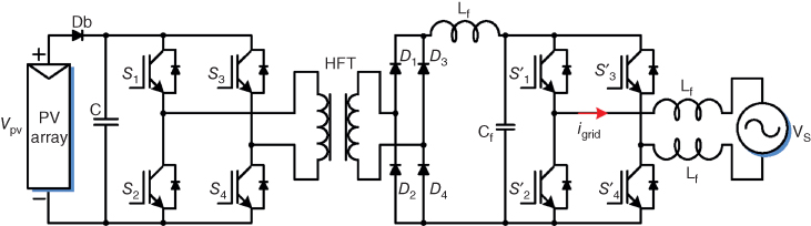
Figure 13.10 PV system with high-frequency transformer.
13.8.1 Transformerless PV Inverter Topologies
Since a transformer imposes an efficiency drop and as high efficiency is one of the most important characteristics of a PV inverter; thus, whenever possible, these inverters are non-isolated electronic circuits. Hence, many trasformerless systems have been designed as discussed later [7]. Transformerless PV inverters use different solutions to minimize the leakage ground current and improve the efficiency of the whole system.
When no transformer is used in a grid-connected PV system, a galvanic connection between the grid and the PV array exists. As a consequence, a common-mode resonant circuit appears, consisting of the stray capacitance between the PV modules and the ground, the dc and ac filter elements and the grid impedance. A varying common-mode voltage can excite this resonant circuit and generate a common-mode current. In order to avoid these leakage currents, different inverter topologies that generate no varying common-mode voltages, such as the half-bridge and the bipolar pulse-width modulation (PWM) full-bridge topologies, have been proposed. One of them is to connect the midpoint of the dc-link capacitors to the neutral of the grid, such as the half-bridge, neutral-point clamped (NPC) or three-phase full bridge with a split capacitor topology, thereby continuously clamping the PV array to the neutral connector of the utility grid. Half-bridge and NPC type of converters have very high efficiency, above 97%, as shown in [7]. The H-bridge is a well-known topology, and it is made up of two half-bridges as shown in Fig. 13.11. Most single-phase HB inverters use unipolar switching in order to improve the injected current quality of the inverter, which is done by modulating the output voltage to have three levels with twice the switching frequency. Moreover, this type of modulation reduces the stress on the output filter and decreases the losses in the inverter. A disadvantage of half-bridge and NPC type of converters is that, for single-phase grid connection, they need a 700-V dc link.

Figure 13.11 H-bridge inverter.
The bipolar PWM full-bridge requires a lower input voltage but exhibits a low efficiency. In the bipolar PWM, the diagonal pairs of switches ![]() and
and ![]() and
and ![]() and
and ![]() (Fig. 13.12) are controlled in a complementary manner. Therefore, two output voltage levels
(Fig. 13.12) are controlled in a complementary manner. Therefore, two output voltage levels ![]() and
and ![]() can be obtained. The common-mode voltage is nearly constant because zero-voltage state does not exist. The common-mode voltage varies only with low-frequency grid voltage. The RMS value of the leakage current is very low. Unfortunately, because of bipolar switching, this scheme imposes high voltage stress and high inductor current ripple, which is associated with additional losses. The high power losses are due to two factors. The first is the internal reactive power flow inside the inverter. The second is the double switching frequency required to obtain the same inductor current ripple frequency. It is therefore desired to develop new topologies to combine the advantages of the bipolar PWM (low leakage current level) and those of the unipolar PWM (high efficiency, low current ripple and three-level inverter output voltages). This can be done by adding extra switches to the full-bridge topology. These extra switches would disconnect the PV array from the grid during freewheeling period.
can be obtained. The common-mode voltage is nearly constant because zero-voltage state does not exist. The common-mode voltage varies only with low-frequency grid voltage. The RMS value of the leakage current is very low. Unfortunately, because of bipolar switching, this scheme imposes high voltage stress and high inductor current ripple, which is associated with additional losses. The high power losses are due to two factors. The first is the internal reactive power flow inside the inverter. The second is the double switching frequency required to obtain the same inductor current ripple frequency. It is therefore desired to develop new topologies to combine the advantages of the bipolar PWM (low leakage current level) and those of the unipolar PWM (high efficiency, low current ripple and three-level inverter output voltages). This can be done by adding extra switches to the full-bridge topology. These extra switches would disconnect the PV array from the grid during freewheeling period.

Figure 13.12 Bipolar inverter.
The most widely and simplest topology used in three-phase systems is the full-bridge inverter, which consists of three legs, each leg with two switches.
13.9 Filters for Grid-Connected PV Inverters
In a single-phase current-source inverter (CSI), the pulsating instantaneous power of twice the system frequency generates even harmonics in the dc-link current. These harmonics reflect onto the ac side as low-order harmonics in the current and voltage. Undesirably, these even harmonics affect MPPT in PV system applications and reduce the PV lifetime. In order to mitigate the impact of these dc-side harmonics on the ac side and on the PV, the dc-link inductance must be large enough to suppress the dc-link current ripple produced by these harmonics.. Practically, large dc-link inductance is not acceptable, because of its cost, size, weight and the fact that it slows MPPT transient response. To reduce the necessary dc-link inductance, a parallel resonant circuit tuned to the second-order harmonic is employed in series with the dc-link inductor. The filter is capable of smoothing the dc-link current by using relatively small inductances. Even though the impact of the second-order harmonic is significant in the dc-link current, the fourth-order harmonic can also affect the dc-link current, especially when the CSI operates at high modulation indices. Therefore to improve the parallel resonant circuit, a double tuned resonant circuit tuned to double and fourth order frequency can be used.
13.10 Islanding Detection Methods
Islanding condition of grid-connected PV inverters refers to the condition when “a portion of the utility system that contains both load and distributed resources” remains energized while it is isolated from the remainder of the utility system. In case of low-power PV systems, it must be stopped within 2 s of the formation of the unintentional island in order to avoid possible damages to local electrical loads or the PV inverter during the grid reconnection. Moreover, this condition can be mandatory in order to guarantee the safety of workers during maintenance. Therefore, it is desirable to incorporate detection functions into PV inverters for protection.
The islanding detection methods can be broadly classified into active, passive and communication-based techniques. Passive methods were proposed in the initial phases when the interconnection of PV system was made to the grid. Then as the technology advanced, there has been increase in the number of active methods. Active methods have been proposed to overcome the shortcomings of passive methods. Communication-based methods are reliable but not economical as compared to passive and/or active methods. A reliability measure of a good islanding detection scheme is non-detection zone (NDZ). Good islanding detection method should have negligible NDZ.
In passive methods, under/over-voltage and under/over-frequency relays are placed on the distribution feeders for the detection of various types of abnormal conditions. Now for islanding condition, these relays must cease the operation of the PV system when it is isolated from utility. The behaviour of the system at the time of utility disconnection depends on the change in active and reactive power at the instant before the island is formed. It relies on the detection of an abnormality in the voltage at the point of common coupling (PCC) between the PV inverter and the utility. The parameters vary greatly at the point of the PCC when the system is islanded. The difference between a normal grid-connected condition and an islanding condition is based on the threshold setting of the system parameter.
Active methods actively attempt to create an abnormal PCC voltage when the utility is disconnected, but the action is taken on the utility side of the PCC. In this case, a controlled disturbance is introduced at the PCC, and when the islanding condition occurs, the disturbance results into the detection threshold, minimizing the NDZ.
The concept of this method is that small-disturbance signal will become significant upon entering the islanding mode of operation in order to help the inverter to cease power conversion. Hence, the values of system parameter will be varying during the cessation of power conversion, and by measuring the corresponding system parameters, islanding condition can be detected.
Diverse methods, such as impedance measurement or detection slip mode frequency shift, active and reactive power variations and active frequency drift, have been proposed but they have drawbacks, as they introduce a disturbance at the PCC and interaction between PVs must be considered.
Communication-based methods involve a transmission of data between the inverter or system and utility systems, and the data is used by the PV system to determine when to cease or continue operation.
13.11 Operation and Control of Grid-Connected Wind Energy System
Conventional power stations are usually connected to the high-voltage or extra-high-voltage system, while wind turbines may be connected to ac system at various voltage levels, including the low-voltage, medium-voltage, high-voltage as well as to the extra-high-voltage system. The suitable voltage level depends on the amount of power generated. In the earlier stage, the technology used in wind turbines was based on a squirrel-cage induction generator connected directly to the grid. But in this case, power pulsations in the wind are almost directly transferred to the electrical grid. Furthermore, there was no control of the active and reactive power except from some capacitor banks, which are important control parameters to regulate the frequency and the voltage in the grid system. As the power range of the turbines increased, these control parameters became very important, and power electronics is introduced as an interface between the wind turbine and the grid.
Nowadays, wind turbines are connected to variable-speed generators with power electronics interface. The variable-speed operation of a wind turbine can be achieved depending on the large or a narrow wind speed range [8]. The main difference between wide and narrow wind turbine speed range is the energy production and the capability of noise reduction. A broad speed range gives larger power production and causes reduction of the noise in comparison to a narrow speed range system. Variable-speed operation is typically achieved by using one of two different configurations. The first employs a synchronous generator (SG) that spins at variable speeds and uses a full power converter to ensure that the produced power matches in frequency and phase to that of the utility grid. The second, and most common way of achieving variable-speed operation, is to use a doubly fed induction generator (DFIG). Variable-speed operation can only be achieved by decoupling the electrical grid frequency and mechanical rotor frequency of wind turbine. To achieve this, power electronic converters such as an ac-dc-ac converter combined with advanced power control techniques are used. Presently, DFIG equipped with partial-scale power converter is the most commonly employed configuration. However, the configuration with SG with full-scale power converter is becoming the preferred technology choices in the best-selling power ranges of the wind turbines. Both these technologies are already discussed in the earlier chapters.
13.11.1 Grid Integration of Wind Turbine System
The fluctuation and unpredictable nature of wind energy are undesirable for grid operation. Integration of large-scale wind power may have severe impacts on the power system operation. Traditionally, wind turbines are not required to participate in frequency and voltage control. However, in recent years, attention has been increased on wind farm performance in power systems. Consequently, some grid codes have been defined to specify the steady and dynamic requirements that wind turbines must meet in order to be connected to the grid. Most of the countries have strict requirements for the behaviour of wind turbines, known as grid codes, which are updated regularly. Basically, the grid codes are always trying to make the WTS to act as a conventional power plant from the electrical utility point of view. That means the WTS should not only be a passive power source simply injecting available power from the wind, but also act as an active generation unit. The WTS must be able to manage the delivered active/reactive power according to the demands and provide frequency/voltage support for the power grid.
According to most of the grid codes, the individual wind turbines must be able to control the active power at the PCC. Normally, the active power has to be regulated based on the grid frequency, so that the grid frequency can be somehow maintained. Similarly, the reactive power delivered by the WTS also has to be regulated in a certain range depending on the active power. This will lead to larger MVA capacity when designing the full power converter system. In addition, the reactive power range of the WTS is also specified according to the grid voltage levels. Most modern turbine generators are decoupled from grid frequency through power electronics. Therefore, the inertia of the generator and the turbine rotor do not automatically participate in the grid inertial response as would traditional SGs. Further, because of this decoupling, changes in grid frequency do not elicit an automatic governor response that is common with conventional generation sources. In countries and regions with relatively isolated grids and relatively large levels of wind penetration, participation in grid frequency regulation by wind turbines and wind plants is crucial.
The various active power control requirements laid out by grid operators have resulted in technological development in wind turbine control. The advancements have been made at both individual turbine and wind plant scales. Technologies to provide response in all of the inertial, primary and secondary timescales have been developed at the individual turbine. Similarly, methods for providing active power control of entire wind plants have also been developed. Performing active power control collectively across a wind plant is intended to provide faster response and recovery to grid frequency deviations than can be achieved by performing active power control on individual turbines separately.
To reduce the impact of the wind gust and ensure the security and stability of grid operation, the wind turbines or wind farms are preferred to be configured as distributed generation networks (with many small-size power stations connected to the medium voltage distribution grid), whose power flows and electrical behaviours are different compared with the traditional centralized generation networks (with only a few large-sized power stations connected to the high-voltage transmission grid). Therefore, the protection schemes of the future grid utilities with more wind penetration should be also changed – resulting in a more distributed protection structure and may allow the islanding operation of some wind turbine units and local loads, which are composed as microgrids.
13.11.2 Power Electronics in Wind Energy System
Variable-speed wind turbines are able to operate at an optimal rotation speed as a function of the wind speed. The power electronic converter may control the turbine rotation speed to get the maximum possible power by means of a maximum power point tracking (MPPT) algorithm. In this way, it is also possible to avoid exceeding the nominal power if the wind speed increases. At the same time, the dc-link capacitor voltage is kept as constant as possible, achieving a decoupling between the turbine-side converter and the grid-side converter. A simple grid-connected wind energy system is shown in Fig. 13.13. Cage induction generators and SGs may be integrated into power systems with full rated power electronic converters. The wind turbines with a full-scale power converter between the generator and the grid give the added technical performance. Usually, a back-to-back voltage-source converter (VSC) is used in order to achieve full control of the active and reactive power. The grid-connected converter will work as an inverter, generating a PWM voltage whose fundamental component has the grid frequency and also being able to supply the active nominal power to the grid.

Figure 13.13 Wind energy system.
13.11.3 Control of Doubly Fed Induction Generator–Based Wind Turbine Systems
At present, the configuration of DFIG equipped with partial-scale power converter is dominating the market, The DFIG-based WTS configuration with partial-scale back-to-back power converters is shown in Fig. 13.14 The stator side of the DFIG is directly connected to the grid, while a partial-scale power converter is responsible for the control of the rotor frequency as well as the rotor speed [9]. The power rating of the partial-scale converter settles the speed range to about ![]() of synchronous speed. Moreover, the converter performs as a reactive power compensator and a smooth grid interconnection. Smaller power converters are economical compared to full-scale converter. However, the main drawbacks are the use of slip rings, some protection schemes and the controllability under grid faults. The rotor-side converter (RSC) controls the DFIG's rotor speed and power, while the grid-side converter (GSC) controls the dc-bus voltage and performs reactive power compensation as well.
of synchronous speed. Moreover, the converter performs as a reactive power compensator and a smooth grid interconnection. Smaller power converters are economical compared to full-scale converter. However, the main drawbacks are the use of slip rings, some protection schemes and the controllability under grid faults. The rotor-side converter (RSC) controls the DFIG's rotor speed and power, while the grid-side converter (GSC) controls the dc-bus voltage and performs reactive power compensation as well.

Figure 13.14 DFIG-based wind energy system.
The objective of the grid-side converter or the GSC is to permit the active power flow, regulating the dc-link voltage to a constant level. Close-to-unity power factor operation is usual, but it is also possible to control the reactive power flow between the converter and the stator/grid. Vector control is one of the most widely used control schemes for the rotor-side converter in DFIG-based WTS. The dq reference frames in a vector control can be aligned either to the grid voltage or to the stator flux. Upon aligning the direct axis of the reference frame with the stator voltage position, ![]() , becomes zero, and
, becomes zero, and ![]() is then equal to the amplitude of the terminal voltage. Then the active power depends on
is then equal to the amplitude of the terminal voltage. Then the active power depends on ![]() and reactive power on
and reactive power on ![]() , thus independent control of the active and reactive power flowing between the grid and the GSC can be obtained. Since the stator currents are related to the rotor currents by adjusting the rotor voltage appropriately, the desired rotor currents and, hence, the desired stator currents corresponding to the optimal electromagnetic torque and the desired Var flow/power factor can be achieved.
, thus independent control of the active and reactive power flowing between the grid and the GSC can be obtained. Since the stator currents are related to the rotor currents by adjusting the rotor voltage appropriately, the desired rotor currents and, hence, the desired stator currents corresponding to the optimal electromagnetic torque and the desired Var flow/power factor can be achieved.
The grid-side PWM converter should have the ability to control the dc-link voltage, in order to ensure that the active power from the GSC can be delivered into the grid. At the same time, the ability of controlling the reactive power is required by the grid codes as well. The control of GSC in DFIG is similar to the control of other grid-connected converter, the d-axis is aligned with the grid voltage vector and the dc-link voltage is controlled with the d-axis output current ![]() , while the reactive power Q is controlled by the q-axis current
, while the reactive power Q is controlled by the q-axis current ![]() .
.
In order to work effectively, the power converter must be controlled in collaboration with the wind turbine pitch control. In other words, given a particular wind speed, there is a unique rotational speed required to achieve the goal of maximum power tracking (MPT). At below the rated wind speed, the wind turbine operates in the variable-speed mode, and the rotational speed is adjusted such that the maximum value of ![]() is obtained. With increasing wind speed, the rotational speed of wind turbine increases. Once the rotor speed exceeds its upper limit, the pitch controller will begin to increase the pitch angle to shed some of the aerodynamic power.
is obtained. With increasing wind speed, the rotational speed of wind turbine increases. Once the rotor speed exceeds its upper limit, the pitch controller will begin to increase the pitch angle to shed some of the aerodynamic power.
13.11.3.1 Control of a DFIG under Unbalanced Grid
Under unbalanced network condition, there are four rotor current components, two positive sequence and two negative sequence. Under unbalanced conditions, the positive- and negative-sequence currents of both RSC and GSC should be controlled independently, so as to meet the reactive support requirement of the grid code. It is clear from that the unbalanced grid voltage can bring double-grid-frequency oscillations on the GSC power and dc-link voltage. As the dc-link voltage fluctuations may cause harmonics in the converter output, as well as the over- or under-voltage protection, resulting in tripping of the converters, the GSC must be made to eliminate them. In this case, the aim of the control system is no longer to regulate the grid voltage.
Producing appropriate rotor voltage and current by the control of the rotor-side voltage and current is the key to enhancing DFIG unbalanced operation capacity, thus the control goal can be succeeded. One of the recent techniques is described as follows.
The double-synchronous rotating frame (SRF) control strategy is based on the symmetrical component method, where the rotor's positive- and negative-sequence currents in the positive and negative SRF are controlled respectively based on the DFIG's mathematical model in positive and negative SRF. The rotor's positive-sequence current reference set is based on the controlling function of the DFIG's average active power (average torque) and average reactive power, and the rotor's negative-sequence current set is based on the unbalance control target. The positive- and negative-sequence vector orientation of stator voltage is used respectively in the positive-synchronous rotating coordinate system and the negative-synchronous rotating coordinate system.
13.11.4 PMSG-Based Wind Energy Conversion System
In a variable-speed WECS, the generator can be an asynchronous generator, an electrically excited synchronous generator (WRSG) or a permanent magnet synchronous generator (PMSG). The variable-speed WECS offers advantages over the constant speed approach, such as MPPT capability and reduced acoustic noise at lower wind speeds.
PMSGs have the advantages of being robust in construction, very compact in size, not requiring an additional power supply for magnetic field excitation and requiring less maintenance [9]. These systems require full rated PE converters and can work on full speed.
A direct power conversion PM generator connected to grid is shown in Fig. 13.15. It can be used with variable-pitch variable speed with or without gearbox wind turbine system. The three-phase variable voltage, variable-frequency output from the wind turbine is rectified using a converter. The presence of dc link performs control of decoupling between the turbine and the grid. The dc link also gives an option of connecting batteries as energy storage and their charging. The dc signal is then inverted by grid-side converter into a three-phase, 50/60 Hz waveform. This waveform can then be scaled using a transformer to voltage levels required by the utility's ac system. The generator is decoupled from the grid by a voltage-sourced dc-link; therefore, this PE interface provides excellent controllable characteristics for the wind energy system. The power electronic devices are used to control the speed of wind turbine, to decouple the PMSG from the power grid, and the WECS does not need to synchronize its rotational velocity with the electrical network frequency.

Figure 13.15 PM-generator-based wind energy system.
The generator-side converter is used to regulate the velocity of WTG, which enables optimal speed tracking for the optimal power capture from any particular wind speed. The grid-side converter is used to stabilize the dc-link system voltage, to deliver the energy from the PMSG sides to the electric network system and to set a UPF of WFS during wind variation. For this reason, direct power control (DPC) is adopted to control instantaneous values of reactive power and active power of network connection, respectively. Moreover, the input reactive power and active power are controlled in d-q synchronous reference frame. Accordingly, the PI control loops are used. Normally, a dc chopper is introduced to prevent overvoltages of dc link in case of grid faults when extra turbine power needs to be dissipated as the sudden drop of grid voltage.
The MPPT controller generates the reference speed of the generator, which when applied to the velocity control loop of the PMSG-side converter control system, maximum power will be produced by the VS-WECS. For this reason, vector control scheme is used as the control strategy for the generator-side converter with double closed-loop regulation. For the GSC, the current flowing in the generator stator should be controlled to adjust the generator torque and consequently the rotating speed. This will contribute to the active power balance in normal operation when the maximum power is extracted [10].
For the line-side (grid-side) converter (LSC), it should have the ability to control the dc-link voltage, ![]() , in order to ensure that the active power from the GSC can be delivered into the grid. At the same time, the ability of controlling the reactive power is required by the grid codes as well. Similarly to the control of other grid-connected converter, the d-axis is aligned with the grid voltage vector and the dc-link voltage
, in order to ensure that the active power from the GSC can be delivered into the grid. At the same time, the ability of controlling the reactive power is required by the grid codes as well. Similarly to the control of other grid-connected converter, the d-axis is aligned with the grid voltage vector and the dc-link voltage ![]() is controlled with the d-axis output.
is controlled with the d-axis output.
So, in the inside loop, the current controllers are used to regulate q-axis and d-axis stator current to follow the command, whereas a velocity controller is used in the outside loop to regulate the WTG speed in order to follow the command value and produces corresponding q-axis current command.
It is important to note that it is fundamental to confine the converted mechanical power during high wind velocities and if the turbine extracted power reaches the nominal power. Then, power limitation can be realized by pitch control, stall control or active stall system.
13.11.4.1 Current-Source-Based PMSG
In most of the wind energy converter systems using PMSG, voltage control inverters are used. However, CSCs have some distinct advantages and are being considered for applications in WEC systems [11]. A CSC requires a dc-link inductor to provide a smooth dc current for operation. The grid-side converter in a CSC is a CSI which converts the dc-link current to three-phase ac currents that can be accepted by the grid. Contrary to VSIs which are voltage-buck converters, CSIs are essentially voltage-boost converters. Several CSC topologies can be used in the WECS. The grid-side converter can be chosen between a PWM CSI and a phase-controlled thyristor converter; whereas for the generator side, diode rectifier, thyristor rectifier and PWM current-source rectifier (CSR) are possible choices.
Here a back-to-back PWM current-source converter (CSC) topology is described for high-power wind energy applications. Compared with VSC configurations, PWM CSCs provide a simple topology solution and excellent grid integration performance, such as sinusoidal current and fully controlled power factor. The dc-link reactor provides natural protection against short-circuit fault, and therefore, the fault ride through strategy required by the grid code can be integrated easily into the system. As shown in Fig. 13.16, the proposed configuration consists of a PMSG, a full-power back-to-back CSC and a grid-connected transformer. The back-to-back converter consists of a generator-side converter, a grid-side converter and filter capacitors at both sides. The generator-side and grid-side converters are connected via a dc-link choke. Filter capacitors are connected in parallel at both sides to assist current commutation as well as filter out switching harmonics. A step-up transformer is employed to connect the converter to the grid, providing isolation and grid integration.

Figure 13.16 Current source converter–based PMSG.
The operation of the CSCs requires a constant current source, which could be maintained by either a generator-side or a grid-side converter. Generally, the grid-side converter controls the dc-link current based on the assumption of a stiff grid. But the actual dc-link current is determined by the power difference of both sides. The power disturbances of the generator output, mainly due to the disturbances of wind speed, are not simultaneously reflected by the grid-side converter control.
13.12 Summary
In this chapter, wind turbine systems with different generators and power electronic converters are described. Different types of wind turbine systems have quite different performances and controllability. The direct-drive PMSG system has its average efficiency of 2.3% and 1.6% higher than the fixed-speed SCIG system at the 500 kW and 3 MW rated power, respectively. The multiple-stage geared-drive DFIG concept is still dominant in the current market. Additionally, the interest in the direct-drive or geared-drive concepts with a full-scale power electronic converter is emerging. Current developments of wind turbine concepts are mostly related to offshore wind energy; variable-speed concepts with power electronics will continue to dominate and be very promising technologies for large wind farm. The performance of PMs is improving and the cost of PMs is decreasing in recent years, which make variable-speed direct-drive PM machines with a full-scale power converter more attractive for offshore wind power generations.
References
- 1 Blaabjerg, F. et al. (2006) Overview of control and grid synchronization for distributed power generation systems. IEEE Transactions on Industrial Electronics, 53 (5), 1398–1409.
- 2 Carrasco, J.M. et al. (2006) Power-electronic systems for the grid integration of renewable energy sources: A survey. IEEE Transactions on Industrial Electronics, 53 (4), 1002–1016.
- 3 Kowalaska, T.O. et al. (eds) (2014) Advanced and Intelligent Control in Power Electronics and Drives, Springer.
- 4 Khalifa, A. S. and El-Saadany, E. F. (2009) Control of 3-phase grid connected photovoltaic power systems. Proceedings International Conf. I PEMC.
- 5 Kjare, S.B. et al. (2005) A review of single-phase grid-connected inverters for photovoltaic modules. IEEE Transaction on Industry Applications, 41 (5), 1292–1306.
- 6 Jain, S. and Agarwal, V. (2007) A single-stage grid connected inverter topology for solar PV systems eith maximum power point tracking. IEEE Transactions on Power Electronics, 22 (5), 1928–1940.
- 7 Gonzalez, R. et al. (2007) Transformerless inverter for single-phase photovoltaic systems. IEEE Transaction on Power Electronics, 22 (2), 693–697.
- 8 Siegfried, H. (1998) Grid Integration of Wind Energy Conversion Systems, John Wiley & Sons.
- 9 Cardenas, R. et al. (2013) Overview of control systems for the operation of DFIGs in wind energy applications. IEEE Transactions Industrial Electronics, 60 (7), 2776–2798.
- 10 Errami, Y (2011) Modelling and control strategy of PMSG based variable speed wind energy conversion system. International Conference on Multimedia Computing and Systems (ICMCS).
- 11 Dai, J. (2009) A novel control scheme for current-source-converter-based PMSG wind energy conversion systems. IEEE Transaction on Power Electronics, 24, 963–972.