
Chapter 11
Fuel Cells
11.1 Fuel Cell Technologies
A fuel cell is an electrochemical device that converts chemical energy (of a fuel) directly into electrical energy. Since the chemical energy of the fuel is directly converted to electricity, a fuel cell can operate at much higher efficiencies than internal combustion engines, extracting more electricity from the same amount of fuel. Fuel cells are capable of converting 40% of the available fuel to electricity. This can be raised to 80% with heat recovery. The fuel cell itself has no moving parts, offering a quiet and reliable source of power.
The fuel cell was invented by William R Grove in 1839. It was then called gaseous voltaic battery. In 1882, Lord Rayleigh developed a new form of gas battery which was an attempt to improve the efficiency of the cell [1]. A fuel cell is similar to a battery because both batteries and fuel cells convert chemical potential energy into electrical energy. In this process, heat energy is also produced as a by-product. However, the basic difference between fuel cell and batteries is that in batteries, the chemical energy is stored in the substances located inside them. When this energy has been converted to electrical energy, the battery must be discarded or recharged appropriately. In a fuel cell, the chemical energy is provided by a fuel and an oxidant stored outside the cell in which the chemical reactions take place. As long as the cell is supplied with the fuel (hydrogen) to the anode and source of oxygen usually air as oxidant, electrical power can be generated.
In the fuel cell, there is no combustion involved; instead, oxidation of the hydrogen takes place electrochemically in a very efficient way. During this process, electricity, water and heat are produced. Fuel cells are power-generating devices having a wide range of applications including stationary power generation (MW), portable power generation (kW) and transportation (kW). Because of this, they may be used in almost every application where local electricity generation is needed. For example, these cells find applications in automobiles, buses, utility vehicles, scooters, bicycles and submarines. Fuel cells offer tremendous flexibility in terms of distributed power generation, at a level of individual homes, buildings or a community. As a backup power generator, fuel cells offer several advantages over either internal combustion engine generators (noise, fuel, reliability, maintenance) or batteries (weight, lifetime, maintenance). Small fuel cells are attractive for portable power applications, either as replacement for batteries (in various electronic devices and gadgets) or as portable generators.
Every fuel cell has two electrodes, one positive and one negative, called, respectively, the anode and cathode. It also has an electrolyte, which carries electrically charged particles from one electrode to the other, and a catalyst, which speeds the reactions at the electrodes. The reactions that produce electricity take place at the electrodes.
Most common electrolyte in fuel cell is hydrogen, as it is the simplest element. An atom of hydrogen consists of only one proton and one electron. It is also available in large quantity. But despite its simplicity and abundance, hydrogen does not occur naturally as a gas on the Earth – it is always combined with other elements. For example, water is a combination of hydrogen and oxygen.
The most significant advantages of fuel cells are low emission of greenhouse gases, quiet operation and high power density. The energy density of a typical fuel cell is 200 Wh/l, which is nearly 10 times that of a battery [1–4]. A fuel cell responds rapidly to sudden increase or decrease in power demands, because the electricity is generated by a chemical reaction.
11.2 Types of Fuel Cells
Fuel cells are available in various power ranges: from very small devices producing only a few watts of electricity [5] to large power plants producing many megawatts. However, all fuel cells are designed using two electrodes separated by a solid or liquid electrolyte that carries electrically charged particles between them. A catalyst is often used to speed up the reactions at the electrodes. Fuel cell types are generally classified according to the nature of the electrolyte they use. This classification determines the kind of electrochemical reactions that take place in the cell, the kind of catalysts required, the temperature range in which the cell operates, the fuel required and other factors. These characteristics, in turn, affect the applications for which these cells are most suitable.
Fuel cells can be classified into six different categories based on the type of electrolyte used. These are as follows:
- Proton exchange membrane fuel cell (PEMFC)
- Solid oxide fuel cell (SOFC)
- Molten carbonate fuel cell (MCFC)
- Phosphoric acid fuel cell (PAFC)
- Alkaline fuel cell (AFC)
- Direct methanol fuel cell (DMFC).
11.3 Proton Exchange Membrane (PEM) Fuel Cell
Among all kinds of fuel cells, PEMFCs are being rapidly developed as the primary power source in movable power supplies and distributed generation (DG), because of their high energy density, low working temperature, quick start-up and simplicity. A PEM fuel cell is an electrochemical cell that is fed hydrogen, which is oxidized at the anode, and oxygen that is reduced at the cathode. The protons released during the oxidation of hydrogen are conducted through the proton exchange membrane at the cathode. PEM fuel cells use a solid polymer as an electrolyte and porous carbon electrodes containing a platinum or platinum alloy catalyst. The electrodes must be porous because the reactant gases are fed from the back and must reach the interface between the electrodes and the membrane, where the electrochemical reactions take place on the catalyst surface. The large amount of platinum in original PEM fuel cells is one of the reasons why fuel cells were not commercialized earlier. New research has been directed in reducing the use of platinum in electrodes.
PEMFC is the only fuel cell which is being considered for powering passenger cars. It is also being developed for stationary and portable power generation. PEM fuel cell gets its name as it uses a proton conducting polymer membrane as electrolyte. They need only hydrogen, oxygen from the air and water to operate. The polymer membrane has unique property as it is impermeable to gases but conducts protons. It acts as the electrolyte and is squeezed between the two porous, electrically conductive electrodes. These electrodes are typically made out of carbon cloth or carbon fibre paper. A layer with catalyst particles usually of platinum supported on carbon acts as the interface between the porous electrode and the polymer membrane [6–8]. The polymer electrolyte membrane is a solid, organic polymer, usually poly(perfluorosulfonic) acid. The most frequently used membrane in PEM is made of Nafion produced by DuPont. Other types of membranes being researched are polymer–zeolite nanocomposite proton exchange membrane, sulfonated polyphosphazene-based membrane and phosphoric-acid-doped poly(bisbenzoxazole) high-temperature ion-conducting membrane. The Nafion layer is essentially a carbon chain which has a fluorine atom layer attached to it. The membrane must be hydrated for this operation. The electron and proton then meet at the cathode where, in the presence of oxygen, water is formed. Since high temperatures are not necessary to hydrate the membrane, the PEM can be run at very low temperatures, typically at 80 °C or lower.
All electrochemical reactions in a fuel cell consist of two separate reactions: an oxidation at the anode and a reduction at the cathode. Normally, these two reactions would occur very slowly at the low operating temperature of the PEM fuel cell. In order to speed up the reaction, each of the electrodes is coated on one side with a catalyst layer (CL). It is usually made of platinum powder very thinly coated onto carbon paper or cloth. The catalyst is rough and porous, so the maximum surface area of the platinum can be exposed to the hydrogen or oxygen. The platinum-coated side of the catalyst faces the PEM. Platinum-group metals are critical to catalyzing reactions in the fuel cell, but they are very expensive.
11.3.1 Water Management
A PEM fuel cell is shown in Fig. 11.1. The anode and the cathode (the electrodes) consist of a heterogeneous, porous layer that serves as electron conductor, ion conductor and gas transport region. The faces of the electrodes in contact with the membrane (generally referred to as the active layers) contain, in addition to carbon, polymer electrolyte and a platinum-based catalyst. When hydrogen is supplied at the positive electrode (anode), it breaks into electron and proton due to chemical reaction. The proton travels to negative electrode (cathode) through the conductive membrane. The electrons travel through electrically conducting electrodes, through current collectors and through outside circuit and reach other side of the membrane.

Figure 11.1 PEMC fuel cell.
In this system, oxygen may be either pure oxygen or oxygen from the air. The catalytic reaction occurs at the three-phase contact with the catalyst. Here, the catalyst is shown as a platinum site, but any variety of catalysts, usually noble metals, may be employed under different conditions. As the gases react, protons generated at the anode cross the membrane to the cathode as electrons flow through the external circuit to drive reduction. The membrane provides ionic conduction and prohibits direct reaction of the hydrogen and oxygen at the platinum catalyst.
Water management is of vital importance to achieve maximum performance and durability from PEMFCs. On the one hand, to maintain good proton conductivity, the relative humidity of inlet gases is typically held at a large value to ensure that the membrane remains fully hydrated. On the other hand, the pores of the CL and the gas diffusion layer (GDL) are frequently flooded by excessive liquid water. In addition, severe drying conditions can lead to irreversible membrane degradations within about 100 s.
During operation, due to the effect of electro-osmosis, water molecules move from the anode to the cathode resulting in membrane dehydration on the anode side of the membrane and flooding on the cathode side (additional water is produced at the cathode by the reaction
Since the chemical reaction in the cell produces water, it is important that the electrolyte must not be flooded. Flooding of the electrodes causes a decrease in surface area in which the separation of hydrogen or the formation of water takes place. As mentioned earlier, the membrane needs to be hydrated; thus, a balance must be achieved between water removal and hydration of the membrane. The water accumulated in the cathode is usually removed out of the porous electrode via evaporation, water-vapour diffusion and capillary transport through GDL into the flow channels of the flow field and then exhausted out of the system, or else excess water will block the flow.
In removing the water from the cell, care must be taken not to remove too much water from the cathode; otherwise, the membrane and the anode will dry out. Since the electrode is very thin (50 µm), it is possible for the water to leak back to the anode, which would be the ideal situation if the exact amount were to migrate. Several complications arise in this process. The first is that the water naturally moves towards the cathode, about 1–2.5 molecules per proton. This “electro-osmotic drag” is problematic at high current densities because all the water can be removed from the anode, thus causing an abrupt loss in fuel pressure since no water will be present to transfer new protons (this is a form of a mass transportation loss). A further problem in water management is the possibility that the air at high temperature can dry out the water. Studies have shown that at temperatures over 60 °C, the air dries out the cathode. To solve this problem, it is necessary to add water to the system to keep everything hydrated, without flooding. Although these problems have been solved, it is still quite necessary to understand these issues since design of a cell is critically based on water management.
Removal of excess water is also possible by using air which is supplied to the cell to provide oxygen to the cathode. In order not to remove too much water from the cathode, which can dry the membrane and the anode out, it is necessary to have the correct airflow.
11.3.2 Fuel Requirement
For the full commercialization of PEMFC system, a stable supply of high-purity hydrogen is essential. Since hydrogen does not occur naturally as a gas on the Earth, it has to be generated from primary energy sources. PEMFCs function best with high-purity hydrogen gas as the fuel source, but pure hydrogen is unlikely to be the fuel source in the future due to technical and economic considerations in production and storage, especially in applications such as transportation and stationary power generation. Therefore, hydrogen from reformed fuels such as natural gas, gasoline or alcohols is likely to be the fuel that is supplied to the fuel cell. These gas streams will contain small amounts of carbon monoxide (CO) which poisons the platinum anode catalyst. Thus, PEMFCs require that the concentration of carbon monoxide present in the fuel gas should not be more than 10 ppm. In addition, whether carbon dioxide is present in the fuel cell is another important consideration. Presence of CO2 in the fuel gases deteriorates the performance of the fuel cell. Hydrogen can also be produced by reforming of bioethanol, which would then also be a source of renewable hydrogen.
Hydrogen can be produced by the electrolysis of water: splitting of water into its component elements. This process takes place in an electrolyzer, which can be described as a “reverse” fuel cell: instead of combining hydrogen and oxygen electrochemically to produce electricity and water as a fuel cell does, an electrolyzer uses an electrical current and water to produce hydrogen and oxygen.
Electrolysis of water requires source of the electrical current. If grid electricity is used which is normally produced using fossil fuels, the advantage of no pollution is lost. However, if the electricity is obtained from renewable energy such as wind or solar power, the hydrogen can be produced in a completely carbon-free way. Electrolyzers exist, and many commercial versions of various capacities are available on the market. In general, the demand for purity of hydrogen decreases with high operating temperature. High-temperature PEMFCs are now being developed and researched.
11.3.3 Reforming Technologies
Since PEMFC requires hydrogen for its operation, there is an increasing interest in converting current hydrocarbon-based marine fuels such as natural gas, diesel and gasoline into hydrogen-rich gases acceptable to the PEM fuel cells. Reforming can take place either on a very large scale at source or locally at the point of use by small reformers integrated with the fuel cell. Generally, there are two different kinds of reforming for production of hydrogen: external reforming, which is carried out before the fuel reaches the fuel cell itself, and internal reforming, which takes place within the fuel cell stack. External reforming could be carried out at a refinery or chemical plant and the hydrogen delivered by pipeline to filling stations, thereby reducing system cost.
Steam reforming and partial oxidation are methods of hydrogen production used on a large scale industrially, most notably in the production of ammonia and can be used for the production of hydrogen. Fuel is mixed with steam in the presence of a base metal catalyst to produce hydrogen and carbon monoxide. This method is the most well developed and cost-effective for generating hydrogen and is also the most efficient, giving conversion rates of 70–80% on a large scale.
The principal process of converting hydrocarbons into hydrogen by steam reforming involves the following reactions:
In order to obtain a good utilization of the feed for hydrogen production, it is necessary to operate the steam reformer with an outlet temperature around 800–950 °C. Heat has to be supplied to the process to achieve this outlet temperature.
11.3.3.1 Partial Oxidation
In partial oxidation, the methane and other hydrocarbons in natural gas react with a limited amount of oxygen (typically from air) that is not enough to completely oxidize the hydrocarbons to carbon dioxide and water. With less than the required amount of oxygen available, the reaction produces primarily hydrogen and carbon monoxide (and nitrogen, if the reaction is carried out with air rather than pure oxygen) and a relatively small amount of carbon dioxide and other compounds. Subsequently, in a water–gas shift reaction, the carbon monoxide reacts with water to form carbon dioxide and more hydrogen. Partial oxidation is an exothermic process – it gives off heat. The process is, typically, much faster than steam reforming and requires a smaller reactor vessel. However, this process initially produces less hydrogen per unit of the input fuel than is obtained by steam reforming of the same fuel.
11.3.4 Hydrogen Storage
Hydrogen is the lightest chemical element and offers the best energy-to-weight ratio of any fuel. The major drawback of using hydrogen is that it has the lowest storage density of all fuels. However, it is possible to store large quantities of hydrogen in its pure form by compressing it to very high pressure and storing it in containers which are designed and certified to withstand the pressures involved. In this way, it can be either stored as a gas or cooled to below its critical point and stored as a liquid.
Hydrogen can also be stored in solid form, in chemical combination with other elements (there are a number of metals which can “absorb” many times their own weight in hydrogen). The hydrogen is released from these compounds by heating or the addition of water.
11.3.5 Catalysts for PEM Fuel Cell
The CLs play an important role in the performance of PEMFC. In order to improve the performance of the cell, the catalyst must fulfil the following requirements. It must provide high intrinsic activities for electrochemical oxidation of a fuel at the anode and for reduction of dioxygen at the cathode. It should also have good electrical conductivity, be durable and less expensive.
When pure hydrogen is used as the fuel, almost all of the performance losses occur at the cathode. Because of the slower kinetics of oxygen reduction, platinum-based electrocatalysts remain the only practical catalyst material, since they combine both activity and stability in the fuel cell environment. At the anode, losses in cell potential are usually small (less than 50 mV at 2.0 A/cm2) due to the extremely facile nature of the hydrogen oxidation reaction.
However, platinum is very expensive and not available in large quantity on the Earth. Now a group of researchers has shown how to get the same kind of reactivity using nickel as catalyst that is a thousand times less expensive than platinum. Electrodes made using the new catalyst would be about 20% cheaper than those made of platinum.
11.4 Solid Oxide Fuel Cell
SOFCs are high-temperature fuel cells and are operated at temperatures between 600 and 1000 °C. In addition to generating electricity, the high operating temperature also enables waste heat to be used for heating purposes as well as hot water production in homes and for industrial processes. Since these cells operate at high temperatures, they can tolerate relatively impure fuels. These characteristics enable the use of a variety of fuels in these cells. High-temperature SOFCs offer very low levels of NOx and SOx emissions, clean and pollution-free technology to electrochemically generate electricity at high efficiencies.
SOFCs' relatively simple design combined with the significant time required to reach operating temperature and quick response to changes in electricity demand make them suitable for large to very large stationary power applications. In addition, pressurized SOFCs can be successfully used as replacements for combustors in gas turbines; such hybrid SOFC–gas turbine power systems are expected to reach efficiencies over 70%.
The SOFC was first considered following the discovery of solid oxide electrolytes in 1899 by Nernst [9]. He reported that the conductivity of pure metal oxides increased very slowly with temperature and remained relatively low, whereas mixtures of metal oxides can possess dramatically higher conductivities.
The SOFC is characterized by having a solid ceramic electrolyte (hence the alternative name, ceramic fuel cell), which is a metallic oxide. The principle of operation of a SOFC shown in Fig. 11.2 can be described as follows. SOFC essentially consists of two porous electrodes separated by a dense, oxygen ion-conducting electrolyte through which the oxide ions migrate from the cathode side to the anode side where they react with the fuel (H, CO, etc.) to generate the voltage. It is a two-phase system because the fuel and oxidants are fed as gases, and the fuel cell reactions occur at the solid electrode/gas interfaces. After the reaction, it again produces steam and CO2 which are gases.

Figure 11.2 Solid oxide fuel cell.
11.4.1 Electrolytes for SOFC
A major challenge in reducing the operating temperature of SOFCs is the development of solid electrolyte materials with sufficient conductivity to maintain low ohmic losses during operation. Three SOFC electrolytes, yttria-stabilized zirconia (YSZ), rare-earth-doped ceria and rare earth-doped bismuth oxide have been widely investigated as electrolytes for a fuel cell. Of these materials, YSZ has been most successfully employed with a strontium-doped lanthanum manganite (La1 2 xSrxMnO3) cathode and a mixed nickel/YSZ cermet anode and doped lanthanum chromite (LaCrO3) as the interconnect. For optimum cell performance, the YSZ electrolyte must be free of porosity so as not to allow gases to permeate from one side of the electrolyte to the other.
Ceria-based materials have found potential application as electrolyte materials for the intermediate-temperature (500–750 °C) SOFC. ITSOFC is favourable compared to high-temperature SOFC. Several advantages are obtained with the reduction in operating temperature; they are as follows: less prone to thermal and mechanical stress, wide range of material selection, short start-up time, easy maintenance, better thermal management, much more economical.
In general, SOFC consists of two main sections: a reformer part, where the reforming reaction takes place, and a fuel cell part, where the electrochemical reactions occur. The external feed such as methane (in natural gas) is converted to hydrogen and carbon monoxide at the reformer section. In external reforming, the endothermic steam reforming reaction and the fuel cell reactions are operated separately.
Direct reforming of the fuel on the anode offers the simplest and most cost-effective solution and, in principle, provides the greatest system efficiency with least loss of energy. In direct reforming, the anode must perform the following tasks: firstly, as a reforming catalyst, catalyzing the conversion of hydrocarbons to hydrogen and CO; secondly as an electrocatalyst responsible for the electrochemical oxidation of H2 and CO to water and CO2, respectively; and finally, as an electrically conducting electrode. High efficiency results from utilizing the heat from the exothermic electrochemical reaction to reform the hydrocarbon fuel, this being a strongly endothermic reaction. However, one of the major problems with direct reforming is that it gives rise to a sharp cooling effect at the cell inlet, creating non-uniform distribution of temperature. Being endothermic, the direct internal reformation process can have the beneficial effect of reducing the airflow requirement for cell cooling different units.
11.5 Molten Carbonate Fuel Cell
Another high-temperature fuel cell is MCFC which operates at 600–700 °C where the alkali carbonates form a highly conductive molten salt, with carbonate ions providing ionic conduction. MCFC technology operating in a pressurized mode has the potential of a fuel-to-electricity efficiency in the range of 55–60% with NOx emissions of less than 1 ppm.
Internal reforming is possible for this cell. Internal reforming uses the heat produced by the exothermic hydrogen oxidation for the endothermic steam reforming reaction, which simplifies thermal management of the stack.
A MCFC is shown in Fig. 11.3. The defining characteristic of a MCFC is the material used for the electrolyte. The electrolyte is usually mixture of molten carbonate salts (lithium carbonate + potassium carbonate/sodium carbonate) retained in a ceramic matrix (LiAlO2). In the early days of the MCFC, the electrodes were made of precious metals. As the technology developed, nickel was found to be adequate both as a metal for the anode and as nickel oxide (NiO) for the cathode. At the high operating temperatures in MCFCs, Ni (anode) and nickel oxide (cathode) are adequate to promote reaction. Noble metals as catalysts are not required for operation [10]. At the anode, hydrogen reacts with the ions to produce water, carbon dioxide and ions. The electrons travel through an external circuit to provide electrical power before they return to the cathode. At the cathode, oxygen from the air and carbon dioxide recycled from the anode react with the electrons to form ![]() ions that replenish the electrolyte and transfer current through the fuel cell.
ions that replenish the electrolyte and transfer current through the fuel cell.
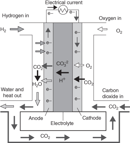
Figure 11.3 Molten carbonate fuel cell.
The electrochemical reactions occurring in MCFCs are as follows:
with the overall reaction as
One of the advantages of the high operating temperature of the MCFC is that the overall thermal efficiency is high, with a potential of 50–60% conversion of the fuel (natural gas) LHV to electricity without recovery and conversion of the exhaust heat. IF the exhaust heat from the MCFC which is at relatively high temperatures (650 °C) may be recovered for the generation of steam which further increases the efficiency. Efficiencies >60% may potentially be achieved with the incorporation of a bottoming cycle. On the other hand, the higher operating temperature places severe demands on the corrosion stability and life of cell components.
Unlike all other fuel cell types, the MCFC relies on a balance in capillary pressures within the pores of the anode and cathode to establish the interfacial electrode/electrolyte boundaries. The thickness of the matrix also plays an important part in the overall ohmic loss associated with the electrolyte.
The major obstacle to the commercial development of MCFCs is the dissolution of cathode. The dissolution of cathode can be described from the equation
Lithium as a cobalt oxide, LiCoO2, has been selected as candidate material for MCFC cathodes because its solubility is small and the rate of dissolution into the melt is slower than that for nickel oxide. On the other hand, the electrical conductivity of LiCoO2 is lower than that of nickel oxide. Thus, nickel oxide has been coated with stable LiCoO2 in carbonate by a PVA-assisted sol–gel method to give a LiCoO2-coated NiO (LC-NiO) cathode. The dissolution of the cathode material has also been minimized by changes in operating conditions and also by altering composition of the melt. Li/Na carbonate is emerging as a preferred electrolyte for MCFCs, although further optimization is likely.
MCFCs demand such high operating temperatures that most applications for this kind of cell are limited to large, stationary power plants. There are two main causes of performance degradation of cell; loss of electrolyte and dissolution of the cathode. Initially, electrolyte is consumed by corrosion reactions with metal hardware in the fuel cell. Over longer time, and at a more constant rate, electrolyte is primarily lost by vaporization into the fuel gas. A careful electrolyte management with improved pore structure to maintain electrolyte within the electrodes has reduced the electrolyte loss due to vaporization. Electrolyte loss is the main cause of performance degradation in atmospheric systems, and NiO dissolution is the main cause in pressurized systems.
11.6 Phosphoric Acid Fuel Cell
Fuel cells which use phosphoric acid solution as the electrolyte are called PAFCs. PAFCs were the first fuel cells to be commercialized. Developed in the mid-1960s and field-tested since the 1970s, they have improved significantly in stability, performance and cost. Such characteristics have made the PAFC as most suitable for stationary application [11].
The number of these cells exceeds any other fuel cell technology and is being used to power many commercial premises. The operating temperature of this cell ranges from 150 to 220 °C. The PAFC operates at greater than 40–45% efficiency in generating electricity. If co-generation is also employed, the overall efficiency is approximately 85%. Furthermore, the waste heat is produced at temperatures capable of heating hot water or generating steam at atmospheric pressure.
A PAFC is shown in Fig. 11.4. The principle of operation is similar to that of PEMFC. The PAFC consists of a pair of porous electrodes made of a finely dispersed platinum catalyst on carbon and a silicon carbide structure that holds the phosphoric acid electrolyte. In PAFCs, protons move through the electrolyte to the cathode to combine with oxygen and electrons, producing water and heat. The charge carrier in this type of fuel cell is the hydrogen ion (H+, proton). At the anode, pure hydrogen or reformate fuel gases with the main component being hydrogen is supplied, and air is supplied at the cathode; the resulting electrochemical reaction yields an electric power output. At the fuel electrode, hydrogen reacts at the electrode surface to become hydrogen ions and electrons, and the hydrogen ions migrate towards the cathode within the electrolyte.

Figure 11.4 PAFC fuel cell.
The phosphoric acid in aqueous solution dissociates into phosphate ions and hydrogen ions given by Eq. (11.6); the hydrogen ions (![]() ) act as the charge carrier.
) act as the charge carrier.
Phosphoric acid has the advantages of good thermal, chemical and electrochemical stability, good capillary properties and low vapour pressures, although it is a poor ionic conductor. Among the common acids, it has the lowest volatility, and this property allows PAFCs to operate even at a temperature of 200 °C (473 K) for several thousand hours.
It also has an extremely wide change of vapour pressure across the face of the cell and as a function of current density, without showing a tendency to dry out or become too dilute. It exhibits high tolerance for reformed hydrocarbons, removal of CO is possible by a shift reaction and CO2 is rejected naturally. The major limitation of this acid is that oxygen reduction is very slow even at high temperatures and pressures.
The voltage obtained from a single fuel cell is from 0.6 to 1.0 V; thus, more single cells are connected in series for achieving a reasonable operating voltage. Together with the electrical connection, the bipolar plates are usually machined so that they can act as gas channels. Since heat is generated in the course of the electrochemical reaction of hydrogen with oxygen, cooling plates are therefore inserted at regular intervals between fuel cells. Cooling water is passed through them to maintain a cell operating temperature of about 200 °C (473 K).
The PAFC system is the most advanced fuel cell system for terrestrial and stationary power generation applications.
11.7 Alkaline Fuel Cell
AFCs are also known as Bacon fuel cells after their British inventor Bacon [12]. Bacon was inspired by the idea of William Grove – that the electrolysis of water could be reversible. Along with PAFCs, AFCs were one of the earliest FCs developed and have been used by NASA. Starting with applications in space, the alkaline cell provided high-energy conversion efficiency with no moving parts and high reliability. In 1939, Bacon built a fuel cell with economically viable catalysts and practical high-pressure equipment and seals that had potassium hydroxide (27%) as electrolyte, a pure asbestos cloth as diaphragm and nickel gauze electrodes. They consume hydrogen and pure oxygen, to produce water, heat and electricity. These products make AFCs ideal for use in space where carbon dioxide production can pose a major threat.
An AFC is shown in Fig. 11.5. It consists of two porous electrodes with liquid KOH electrolyte between them. The hydrogen fuel is supplied to the anode electrode, while oxygen from air is supplied to the cathode. The working temperature ranges from 293 to 363 K. The electrical voltage between the anode and the cathode of a single fuel cell is between 0.9 and 0.5 V depending on the load and the electrochemical reactions taking place at these electrodes. The hydrogen is usually compressed, and the oxygen is obtained from the air. It uses an aqueous solution of potassium hydroxide as the electrolyte, with typical concentrations of about 30%. One advantage of using an alkaline electrolyte is that electrode material other than platinum can be used with less risk of corrosion, especially compared to acid electrolytes. The overall chemical reactions are given by

Figure 11.5 Alkali fuel cell.
The reaction at the cathode occurs when the electrons pass around an external circuit and react to form hydroxide ions, OH−, shown as follows:
resulting in overall cell reaction as
By-product water and heat have to be removed. This is usually achieved by re-circulating the electrolyte and using it as the coolant liquid, while water is removed by evaporation.
AFCs were used in the Apollo space shuttle which took the first men to the moon. Due to the success of the AFC in the space shuttle, they were tested in many different applications including agricultural tractors, power cars and provided power to offshore navigation equipment and boats. The space programme remained an important research on AFCs, and since then, AFCs have improved.
Alkaline electrode fuel cells operate at a wide range of temperatures and pressures, and their application is very limited. As a result, there are different types of electrodes used. Some of the various types of electrodes are explained as follows.
Carbon-supported catalysts are commonly used in the current production of electrodes. The electrodes consist of a double-layer structure: an active electro CL and a hydrophobic layer. The active layer consists of an organic mixture (carbon black, catalyst and PTFE) which is ground and then rolled at room temperature to cross-link the powder to form a self-supporting sheet. The use of non-platinum electrodes greatly reduces the cost of producing the electrodes. The major drawback of AFCs is their exquisite sensitivity to carbon dioxide. Even trace amounts of carbon dioxide can affect the cell's operation substantially by converting the potassium hydroxide electrolyte into potassium carbonate. Potassium carbonate is a solid that blocks pores in the cathode. This reduces the ionic conductivity of fuel cell and diminishes the speed with which the reaction can proceed. The problem of carbon dioxide is present when carbon-supported catalysts are used in the electrode. Several methods have been proposed to reduce the carbon dioxide concentrations: soda lime or ethanol amine scrubbers, physical absorption or removal of CO2 by diffusion of the gas through a membrane. Guzlow in 1996 used an anode based on granules of Raney nickel mixed with PTFE which does not use carbon-supported catalysts to try and solve this problem. Apparently, this type of electrode does not react to the CO2, making it highly favourable for use in this type of application. There is currently some effort in research to produce an AFC in which the potassium hydroxide is replaced at various intervals to maintain operation.
The lifetime of an AFC can, in general, be well over 5000 h for inexpensive terrestrial AFCs and has been shown to be significantly over 10,000 h for space-application AFCs.
11.8 Direct Methanol Fuel Cell
Significant efforts during the last few years have been focused on the direct electrochemical oxidation of alcohol and hydrocarbon fuels. Organic liquid fuels have high energy density, and the enf associated with their electrochemical combustion to CO2 is comparable to that of hydrogen combustion to water. A schematic of a DMFC is shown in Fig. 11.6. The operation of the DMFC system is similar to the operation of the PEM in terms of the physical manufacturing of the cell [13]. The DMFC consists of a proton-conducting membrane at the centre, the solid polymer electrolyte which is used to provide ionic conductivity and avoid the flow of electrons. Electrodes generally consist of expensive noble metal catalyst used to achieve sufficient rate of reaction at a low temperature. Normally, platinum is used as cathode and platinum–ruthenium alloy at anode for DMFC. In DMFC, to obtain useful current densities, the electrodes should have high surface area with respect to geometric area.
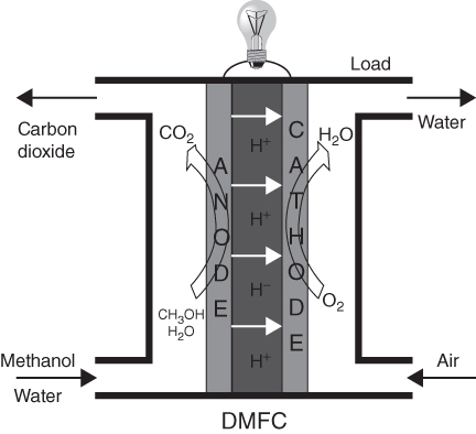
Figure 11.6 Direct methanol fuel cell.
The major difference with PEMFC is in the fuel cell supply. Here the fuel is a mixture of water and methanol; it reacts electrochemically (methanol being oxidized) at the anode to produce carbon dioxide, protons and electrons as shown in Eq. (11.10).
And the overall cell reaction is given by
The cell terminal voltage is 1.15 V.
Methanol and water are supplied and converted to carbon dioxide, protons and electrons at the anode. Methanol can be fed as aqueous solution or in the form of vapour to the anode. The produced electrons from the anode reaction are subsequently transferred via the external circuit (protons and electrons reduce oxygen (from air) to form water at the cathode. This overall reaction occurs at 100% coulombic efficiency with the best electrocatalysts: Pt–Ru for anode and Pt for cathode.
In early 1990s, DMFCs were designed with proton-conducting membranes as the electrolyte using Nafion. With a proton exchange membrane electrolyte (Nafion), the structure of fuel cell is vey similar to that of PEMFC. The structure and composition of the oxygen electrode in DMFC are practically the same as that in PEMFC. The methanol electrode requires a noble metal electrocatalyst loading five to ten times more than for a hydrogen electrode because of the poisoning of the electrode by CO gas. The Teflon contents in the substrate and diffusion layers are lower in the methanol electrode than in hydrogen electrode in order to facilitate the transfer of the liquid fuel methanol to the active layer of the electrode.
One of the most promising applications of DMFCs presently concerns with the field of portable power sources. In this regard, increasing interest is devoted towards the miniaturization of these fuel cell devices in order to replace the current Li-ion batteries. Theoretically, methanol has a superior specific energy density (6000 Wh/kg) in comparison with the best rechargeable battery.
In principle, methanol should be oxidized spontaneously when the anode potential is above 0.046 V, with respect to the reversible hydrogen electrode (RHE). Similarly, oxygen should be reduced spontaneously when the cathode potential is below 1.23 V. In reality, and in common with all fuel cell types, poor electrode kinetics (kinetic losses) cause the electrode reactions to deviate from their ideal thermodynamic values so as to incur a practical reduction of the extremely high theoretical efficiency possible from the cell.
Methanol crossover through the polymer membrane is known to be one of the most challenging problems affecting the performance of DMFCs. The overall efficiency of a methanol fuel cell is determined by both voltage and faradaic efficiency for the consumption of methanol. The faradaic efficiency is influenced mainly by methanol crossover through the membrane. The methanol crossover is usually measured indirectly by determining the amount of CO2 produced at the cathode by the oxidation of methanol on the Pt surface. This CO2 can be monitored on-line by using an IR detector. A more accurate method consists of a chromatographic analysis of samples of the cathode outlet stream. The crossover of methanol is influenced by both membrane characteristics and temperature, as well as by the operating current density. In general, an increase in temperature causes an increase in the diffusion coefficient of methanol and determines a swelling of the polymer membrane. Both effects contribute to an increase in methanol crossover rate.
The crossover rate of methanol at the open-circuit voltage of DMFC at 60 °C is about 100 mA/cm2. This also reduces the open-circuit voltage of the cell as compared to hydrogen fuel cell. The crossover rate decreases with increase in current density and increases with increased methanol concentration. The crossover rate can also be reduced by using alternate membranes, membrane composites or operating at higher temperatures. Presently, research is ongoing in all these directions.
11.8.1 CO Removal
Another problem faced by PEMFC is poisoning of the anode by carbon monoxide which is present in reformed fuel cells. After reforming and water–gas shift, the CO in the reformer gas is usually reduced to 1–2%. A PEMFC requires a low level of CO to less than 10 ppm. This gas is more strongly adsorbed on the surface of the catalyst than hydrogen, effectively blocking the sites where hydrogen oxidation would normally occur. There are a number of ways to clean the raw reformer gas of CO. One method to prevent this from happening is to remove the CO by oxidizing it to carbon dioxide, which does not adsorb on the catalyst, before it can reach and react with the anode surface. This can be accomplished by using the reconfigured anode developed by Los Almos National laboratory. Alternatively, ultra-pure hydrogen without any contaminant can be produced using Pd-membrane technology.
11.9 Fuel Cell Stacks
Since the voltage of a single cell is a very small typical value, the voltage is about 0.7 V when drawing a useful current. It is therefore common to connect a number of fuel cells in series to form a stack. Normally, approximately 50 or more cells are connected to produce a usable voltage. A fuel cell stack consists of a number of single cells stacked up so that the cathode of one cell is electrically connected to the anode of the adjacent cell. Since these cells are connected in series, exactly the same current passes through each of the cells. A better way of forming a stack is to make the connections with bipolar plates made from materials with good conductivity such as graphite or stainless steel. These plates make connections all over one cathode to the anode of the next cell, hence bipolar. The conditions that they must fulfil are that there has to be a good electric connection between the electrodes and that the different gases must be separated.
The bipolar configuration is the best for larger fuel cells since the current is conducted through relatively thin conductive plates; thus, it travels a very short distance through a large area. This causes minimum electroresistive losses, even with a relatively poor electrical conductor such as graphite (or graphite polymer mixtures). The bipolar plate allows the cells to be connected in series and allows gas to be supplied to the anode and cathode.
The choice of materials for producing bipolar plates in commercial fuel cell stacks is dictated not only by the performance considerations but also by cost. However, for small cells, it is possible to connect the edge of one electrode to the opposing electrode of the adjacent cell by some kind of connector. This is applicable only to very small active area cells because current is conducted in the plane of very thin electrodes, thus travelling relatively long distance through a very small cross-sectional area.
Power conditioning includes controlling current (amperes), voltage, frequency and other characteristics of the electrical current to meet the needs of the application. Fuel cells produce electricity in the form of direct current (dc). If the fuel cell is used to power equipment that uses ac, the dc will have to be converted to alternating current.
The key aspects of a fuel cell stack design are as follows:
- Maintainance of uniform distribution of reactants to each cell
- Maintainance of uniform distribution of reactants inside each cell
- Maintenance of required temperature in each cell
- Minimum resistive losses
- No leak of reactant gases (internal between the cells or external)
- Mechanical sturdiness (internal pressure including thermal expansion, external forces)
In order to maintain the desired temperature inside the cells, the heat generated as a by-product of the electrochemical reactions must be taken away from the cells and from the stack. Different heat management schemes may be applied as described as follows.
11.9.1 Cooling with Separate Airflow
Forced convection airflow is a convenient way to bring the waste heat out of the stack. This will result in a more compact stack structure and increase the cooling capability. However, very high cathode airflow velocity or a very large gas channel is necessary for removal of waste heat. When the power of the fuel cell is high, a more effective cooling approach must be applied. Essentially, air cooling method is simple and needs fewer accessories compared to liquid cooling methods, but as the output power increases, it becomes harder to maintain a uniform temperature distribution within the stack by air cooling method and the parasitic losses associated with the cooling fan also increase.
Considering the fact that increasing the cathode air supply for cooling can cause dry out of the membrane, it is reasonable to have separate channels for cooling air to flow through. Thus, separate cooling plates are provided through which air is blown in a separate air cooling system. The advantage of this structure is that it can extract more heat from the stack without affecting the cathode airflow. Air-cooled designs using a bipolar-plate-integrated coolant flow are common for low-temperature PEMFC stacks in the range of 100 W–2 kW. For PEMFC stacks with power output greater than 5 kW, cooling with air may not be sufficient or not as advantageous as the liquid cooling.
11.9.2 Liquid Cooling
Units below 2 kW can be air cooled, and cells between 2 and 10 kW need a careful choice regarding whether air or water cooling should be used. For cells larger than 10 kW, liquid cooling is generally necessary. The liquid coolant is usually deionized water, which has the advantage of very high heat capacity, or an antifreeze coolant, for example, mixture of ethylene glycol and water, for operation under sub-zero conditions. Similarly to the cooling with a separate airflow, liquid coolant flows in the cooling channels, which are usually integrated in the bipolar plates. It is possible to place more than one cell between every two liquid cooling layers to reduce the number of cooling layers. However, it was found that the stack performance would decrease if the number of cells between the two successive cooling layers was increased.
Liquid cooling requires a more complex design: the temperature and pressure of the cooling water must be monitored, and the flow of cooling water must be supplied by a water pump. Stack cooling in DMFCs is relatively simpler since increasing circulation of dilute methanol solution at the anode could remove more waste heat from the stack.
11.10 Fuel Cell Applications
Fuel cells can generate power from a fraction of a watt to hundreds of kilowatts. Because of this, they may be used in almost every application where local electricity generation is required. Fuel cell applications may be classified as being either mobile or stationary applications. The mobile applications primarily include transportation systems and portable electronic equipment while stationary applications primarily include combined heat and power (CHP) systems for both residential and commercial needs. Applications such as automobiles, buses, utility vehicles, scooters, bicycles, submarines have been already demonstrated. Small fuel cells are attractive for portable power applications, either as replacement for batteries (in various electronic devices and gadgets) or as portable power generators.
As a backup power generator, fuel cells offer several advantages over either internal combustion engine generators (noise, fuel, reliability, maintenance) or batteries (weight, lifetime, maintenance). Fuel cell and fuel cell system design are not necessarily the same for each of these applications. On the contrary, each application, besides power output, has its own specific requirements, such as efficiency, water balance, heat utilization, quick start-up, long dormancy, size, weight, fuel supply.
11.10.1 Application in Automobile Industry
For almost a century, electric vehicles have been dependent on lead–acid batteries. The problem with battery is the limit in energy storage: it limits a practical vehicle to a range of about 100 km and a maximum speed of 100 km/h. However, steady advances in fuel-cell technology, new opportunities for hydrogen production and a growing commitment to building hydrogen infrastructure have led many major automakers to think about producing next generation of hydrogen fuel-cell vehicles. All major car manufacturers have demonstrated prototype fuel cell vehicles and have plans for production and commercialization. About 60 million new cars are sold worldwide each year. Several automotive industry leaders have speculated that fuel cell vehicles could account for 20–25% of new car sales within the next 20–25 years, a potential market of 12–15 million vehicles each year. FCVs are currently more expensive than conventional vehicles and hybrids. However, costs have decreased significantly, and it is expected that by 2020, the cost may become competitive.
Buses for city and regional transport are considered to be the most likely types of vehicles for an early market introduction of fuel cell technology. Buses require more power than passenger automobiles, typically about 250 kW or more. They operate in a more demanding operating regime with frequent starts and stops. Nevertheless, the average fuel economy of a bus fuel cell system is roughly 15% better than that of a diesel engine. Buses are almost always operated in a fleet and refueled in a central facility. This makes refueling with hydrogen much easier.
11.10.2 Stationary Power Applications
The stationary application of fuel cells includes CHP, uninterruptible power systems (UPS) and primary power units. Stationary fuel cells can be used as a primary power source. It is often used to power houses that are not connected to the grid or to provide supplemental power. In hybrid power systems, fuel cells can be connected to photovoltaics, batteries, capacitors or wind turbines, providing primary or secondary power. Fuel cells can also be used as a backup or energy power generator providing power when grid supply is not available. Stationary fuel-cell power systems are suitable for DG, allowing the utility companies to increase their installed capacity following the increase in demand more closely, rather than anticipating the demand in huge increments by adding gigantic power plants.
The system design for stationary power application and automotive power applications is similar in principle. The main differences are in the choice of fuel, power conditioning and heat rejection. There are also some differences in requirements for automotive and stationary fuel cell systems. For example, size and weight requirements are very important in automotive applications, but not so significant in stationary applications. The acceptable noise level is lower for stationary applications, especially if the unit is to be installed indoors. The fuel cell itself of course does not generate any noise, but it may be coming from air and fluid handling devices. Automobile systems are expected to have a very short start-up time (fraction of a minute), while the start-up of a stationary system is not time-limited, unless operated as a backup or emergency power generator. Both automotive and stationary systems are expected to survive and operate in extreme ambient conditions, although some stationary units may be designed for indoor installation only. And finally, the automotive systems for passenger vehicles are expected to have a lifetime of 3000–5000 operational hours, systems for buses and trucks somewhat longer, but the stationary fuel-cell power systems are expected to operate for 40,000–800,000 h (5–10 years).
To the end users, the fuel cells offer reliability, energy independence, “green” power and, ultimately, lower cost of energy. Stationary fuel cells may be used in different applications, for example:
11.10.3 Portable Applications
There is a growing demand to supply power for portable electronic equipment both in the consumer market and for the military. The portable market is often regarded as secondary after transport and stationary power, but is nevertheless significant in terms of volume of research and the potential size of the market. Portable fuel cells are lightweight, long-lasting, portable power sources that prolong the amount of time a device can be used without recharging. In comparison, secondary (rechargeable) batteries have battery charger systems that consist of ac chargers that require an outlet to be charged or dc chargers that will recharge batteries from other batteries. Rechargeable batteries are not practical for certain portable and military electronic applications because they can be heavy and not meet the power requirements. Some portable fuel cell applications include laptops, cellular phones, power tools, military equipment, battery chargers, unattended sensors and unmanned aerial and underwater vehicles. Fuel cells offer greater energy density coupled with simple and rapid recharging to give extended operation.
Although much smaller, the military market may well be leading the race to portable fuel cell devices and is a significant source of funding in this area.
11.11 Modelling of Fuel Cell
A simple model of PEM FC is developed here [14]. In order to simplify the modelling and reduce the computation time, the following assumptions are drawn. The gases are ideal and uniformly distributed inside the anode and cathode. The stack is fed with humidified hydrogen and air because the use of humidified fuel and air improves the efficiency of the FC.
The mathematical model equations that describe the operation of the FC consist of the voltage–current characteristics and a relationship for the consumption of the reactants as a function of the current drawn from the fuel cell. The temperature is constant and uniform for each experiment. The gas channels along the electrodes have a fixed volume with small lengths, so that it is necessary only to define a single pressure value in their interior.
11.11.1 Steady-State Model
V-I characteristics of fuel cells can be computed based on physical foundations of fuel cells. In order to model a fuel cell stack, some parameters are required to fit the model. Figure 11.7 shows the steady-state fuel cell characteristic. Typical characteristics of FC are normally given in the form of polarization curve, which is a plot of cell voltage versus cell current density.

Figure 11.7 V-I characterisitc.
To determine the voltage–current relationship of the cell, the cell voltage has to be defined as the difference between an ideal Nerrnst voltage and a number of voltage losses. The main losses are categorized as activation, ohmic and concentration losses.
The steady-state fuel cell voltage, VFC, is then calculated as
![]() voltage is related to the change in Gibbs free energy and to pressure effect. The activation loss is caused by the slowness of the reaction at the surface of the electrodes. The ohmic loss is due to internal resistance of the fuel cell. The concentration losses are generated by the depletion of the reactants at the surface of the electrodes as the fuel is consumed.
voltage is related to the change in Gibbs free energy and to pressure effect. The activation loss is caused by the slowness of the reaction at the surface of the electrodes. The ohmic loss is due to internal resistance of the fuel cell. The concentration losses are generated by the depletion of the reactants at the surface of the electrodes as the fuel is consumed.
Depending on the amount of current drawn, the fuel cell generates the output voltage according to (1). The electric power delivered by the system equals the product of the stack voltage ![]() and the current drawn I:
and the current drawn I:
The V-I characteristic shown in Fig. 11.7 can be modelled using the equivalent circuit shown in Fig. 11.8.
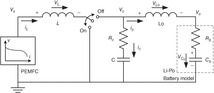
Figure 11.8 Equivalent circuit.
11.12 Summary
A fuel cell combines hydrogen with oxygen (from air) in a chemical reaction, producing water, electricity and heat. Fuel cells do not “burn” the fuel; instead, the conversion takes place electrochemically without combustion. Fuelled with pure hydrogen, they produce zero emissions of pollutant and greenhouse gases at the location of the power plant. In this chapter, different types of fuel cells are presented along with their construction and working.
Fuel cells are connected to form stacks to generate sufficient power. Since lot of heat is produced in the cell during chemical reaction, various methods of cooling are described.
Next, various applications of fuel cells in automobile and stationary applications are discussed. Finally, a simple model of fuel cell for simulation is provided.
References
- 1 Gregor, H. (ed.) (2013) Fuel Cell Technology Hand book, CRC Press.
- 2 O'Hayre, R.P. et al. (2005) Fuel Cell Fundamentals, John Wiley & Sons.
- 3 Srinivasan, S. (2006) Fuel Cells from Fundamentals to Applications, Springer.
- 4 Tim, Z. (ed.) (2007) Advances in Fuel Cells, Elsevier.
- 5 Revankar, S.T. and Majumdar, P. (2014) Fuel Cells: Principles, Design, and Analysis, CRC Press.
- 6 Frano, B. (2013) PEM Fuel Cells Theory and Practice, 2nd edn, Academic Press.
- 7 Christoph, H. and Christina, R. (2012) Polymer Electrolyte Membrane and Direct Methanol Fuel Cell Technology, vol. 1, Woodhead Publishing.
- 8 Hu, L. et al. (2010) Proton Exchange Membrane Fuel Cells, CRC Press.
- 9 Singhal, S.C. (2000) Advances in Solid Oxide Fuel Cell Technology Solid State Ionics, Elsevier.
- 10 Wilimeski, G. and Wolf, T.L. (1983) Molten carbonate fuel cell performance model. Journal of the Electrochemical Science and Technology, 130 (1), 48–55.
- 11 Blomen, L.J.M.J. and Mugerwa, M.N. (1993) Fuel Cell Systems, Plenum Press.
- 12 Hiroko, S. (2009) Alkaline fuel cellsUnesco EOLSS sample chapters, in Energy Carriers and Conversion Systems (ed. T. Ohta), EOLSS.
- 13 Hamnett, A. (1997) Mechanism and electrocatalysis in the direct methanol fuel cell. Catalysis Today, 38 (4), 445–457.
- 14 Ziogou, C. et al. (2010) Modeling and experimental validation of a PEM fuel cell system. 20th European Symposium on Computer Aided Process Engineering – Elsevier.