
Chapter 5
Solar Energy Systems
5.1 Sun as Source of Energy
Solar energy is available directly from the energy produced by the Sun and is used to produce electricity, heat and light in solar energy systems. The Sun gets its energy from the nuclear fusion occurring in its core by converting millions of tons of hydrogen into helium and converting the difference in mass into energy. The Sun is a sphere of diameter 1,400,000 km, and because of nuclear fusion in its core, its outer region comprises hot gases mostly hydrogen and helium and has a surface temperature of 600 K. These gases are confined to the Sun due to the gravitational forces acting on the Sun. At this temperature, the Sun radiates the heat and light which travels through space and reaches the Earth. The rate of energy radiated from the Sun is 3.8 × 10²³ kW. The energy received by the Earth's atmosphere is at an annual average rate of about 1.3–1.4 kW/m2. Out of this energy received, a fraction is reflected by the atmosphere to the space. Still it is estimated that the maximum influx at the Earth's surface is about 1 kW/m2. This amount is so large that at present rate of consumption, the total energy received in 1 h is sufficient to provide energy to the whole world for 1 year. But the problem is that not all the energy received from the Sun can be effectively used because it is thinly spread. In addition, the amount of solar energy which can be used is limited by diurnal and geographic variations and weather conditions. The yearly average values of effective solar irradiation are different at different locations on the Earth. To convert solar energy into useful energy using solar equipment, the precise values of the quality and quantity of solar radiation at a specific location are required.
5.2 Solar Radiations on Earth
The solar radiation reaching the Earth's surface varies because of weather conditions and changing position of the Sun. In 1 year, that is, in 365.25 days, the Earth rotates around the Sun in slightly elliptical orbit. This elliptical orbit has major and minor axes equal to ![]() and
and ![]() , respectively. The Earth also rotates along its polar axis from the North Pole to the South Pole in 24 h. The polar axis is inclined at 23.45° to the plane of elliptical orbit. Because of Earth's inclination, there is difference in energy absorption by the two hemispheres of the Earth and is responsible for seasonal variations in solar radiation. It is also responsible for variations in local temperatures, local weather and wind pattern. Due to different positions of the Earth around the Sun in a year, four different seasons are observed, namely winter, summer, spring and autumn. When the northern hemisphere is having winter, the southern hemisphere will be having summer. Thus, the solar radiation reaching different parts of the globe is different. The annual mean of the solar radiation reaching the Earth's surface is
, respectively. The Earth also rotates along its polar axis from the North Pole to the South Pole in 24 h. The polar axis is inclined at 23.45° to the plane of elliptical orbit. Because of Earth's inclination, there is difference in energy absorption by the two hemispheres of the Earth and is responsible for seasonal variations in solar radiation. It is also responsible for variations in local temperatures, local weather and wind pattern. Due to different positions of the Earth around the Sun in a year, four different seasons are observed, namely winter, summer, spring and autumn. When the northern hemisphere is having winter, the southern hemisphere will be having summer. Thus, the solar radiation reaching different parts of the globe is different. The annual mean of the solar radiation reaching the Earth's surface is ![]() for the oceans and
for the oceans and ![]() for the continents. The extraterrestrial solar radiation is separated into different components when it passes through the atmosphere. Solar radiation propagating in straight line and received at the Earth's surface without change of direction is called direct radiation or beam radiation. Diffused solar radiation is solar radiation received by the Earth after its direction is changed because of scattering by aerosols, dust and molecules. The sum of direct radiation and diffused radiation is the global (total) radiation. A part of the solar radiation reflected by the ground may also be present in total radiation.
for the continents. The extraterrestrial solar radiation is separated into different components when it passes through the atmosphere. Solar radiation propagating in straight line and received at the Earth's surface without change of direction is called direct radiation or beam radiation. Diffused solar radiation is solar radiation received by the Earth after its direction is changed because of scattering by aerosols, dust and molecules. The sum of direct radiation and diffused radiation is the global (total) radiation. A part of the solar radiation reflected by the ground may also be present in total radiation.
For the utilization of solar energy, it is desirable to measure the diffused solar radiation and the global solar radiation [1–3]. Solar irradiance G in w/m2 is the rate at which the radiant energy is incident on a unit area of a surface. It is also known as insolation.
5.2.1 Spectral Distribution of Solar Energy
The Sun emits a continuous spectrum of electromagnetic radiation in a wide frequency range: from very short waves of high energy to long waves with low energy. The spectral distribution of extraterrestrial radiation has a wide spectrum; about half of it lies in the visible part of the electromagnetic spectrum. It produces daylight and can be seen by the human vision system. But nearly half of it also contains the near-infrared and ultraviolet radiations. This spectral distribution is modified in intensity as the radiation crosses the atmosphere downwards, due to scattering by gases and aerosols and by absorption due to atmospheric gases. The energy flow within the Sun results in a surface temperature of 6000 K; hence, the radiation of the Sun resembles the 5800 K blackbody as shown in Fig. 5.1. Electromagnetic radiation as well as solar radiation is commonly classified on the basis of radiation wavelength into several regions or bands. The wavelength bands of solar radiation, both visible and invisible, are mentioned in Table 5.1.

Figure 5.1 5800 K blackbody radiation.
Table 5.1 Wavelength band of solar radiation
| Band | Wavelength (nm) | Atmospheric effects |
| Gamma ray | <0.03 | Completely absorbed by the upper atmosphere |
| X-Ray | 0.03–3 | Completely absorbed by the upper atmosphere |
| Ultraviolet (UV) | ||
| UV (B) | 3–300 | Completely absorbed by oxygen, nitrogen and ozone in the upper atmosphere |
| UV (A) | 300–400 | Transmitted through the atmosphere, but atmospheric scattering is severe |
| Visible | 400–700 | Transmitted through the atmosphere, with moderate scattering of the shorter waves |
| Infrared (IR) | ||
| Reflected (IR) | 700–3000 | Mostly reflected radiation |
| Thermal IR | 3000–14,000 | Absorption at specific wavelengths by carbon dioxide, ozone, and water vapour, with two major atmospheric windows |
As can be seen from Table 5.1, about 99% of extraterrestrial radiation has wavelength in the range of 200–4000 nm with a maximum spectral intensity at 480 nm, which falls within the band of green light. There is almost complete absorption of short-wave radiation of less than 290 nm and infrared radiation above 2300 nm. Thus, the radiation of solar energy in the wavelength range of 290–2300 nm is most significant which can be utilized for different applications.
5.3 Measurement of Solar Radiation
In order to convert the solar energy into useful energy, it has to be properly focussed on a collecting device. All the irradiated energy of the incident solar radiation does not reach the solar collectors when it passes through the earth atmosphere. In order to design a solar thermal system or photovoltaic system, it is important to know the amount of total energy that is received at the solar collector/PV panel. Although solar radiation data is now available for most of the localities, this data is not sufficient because it is mainly about total radiation (direct plus diffuse). But in most cases, separate data of diffuse radiation is required, the computation of which is extremely difficult. However, instruments are available for the measurement of both types of solar radiation [4, 5]. The radiometers used for ordinary observation are pyrheliometers and pyranometers that measure direct solar radiation and global solar radiation, respectively. These are described here.
5.3.1 Pyrheliometer
A pyrheliometer is used to measure direct beam solar radiation from the Sun. In order to measure the direct solar radiation correctly, the instrument is required to be permanently pointed towards the Sun. A two-axis Sun-tracking mechanism that continuously follows the Sun is most often used for this purpose. Different companies manufacture pyrheliometers, and International Pyrheliometer Comparisons take place every 5 years at the WRC in Davos to ensure the worldwide transfer of the world radiometric reference.
Here, Angstrom electrical compensation pyrheliometer which is considered quite simple and shown in Fig. 5.2 is described. It is used for instantaneous measurement of direct solar irradiance from 300 to 4000 nm and is capable of very high accuracy and has very high stability. This pyrheliometer has a rectangular aperture, two Manganin-strip sensors (20.0 mm × 2.0 mm × 0.02 mm) and several diaphragms that allow entry of only direct sunlight. The sensor is mounted in a long metallic tube to collimate the beam and minimize the effect of scattered irradiance. The collimating tube is blackened from the inside and has a about 5.44° field of view. The tube is filled with dry air at atmospheric pressure and its viewing end is sealed by a removable 1-mm-thick crystal quartz window. When solar irradiance is measured with this type of pyrheliometer, the small shutter on the front face of the cylinder shields one sensor strip from sunlight. Thus, sunlight can reach only the other sensor. A temperature difference is therefore produced between the two sensor strips because one gets heated due to solar radiation whereas the other does not. A thermo-electromotive force proportional to this difference in temperature induces current flow through the galvanometer. The heating by direct irradiation received by the exposed strip is compensated by electrically heating the shielded strip till the galvanometer current becomes zero. Electrical power required for heating the shielded strip is proportional to the incident irradiance. If S is the intensity of direct solar irradiance and i is the current in the galvanometer, then ![]() , where K is a constant whose value is determined by comparing with a standard pyrheliometer.
, where K is a constant whose value is determined by comparing with a standard pyrheliometer.
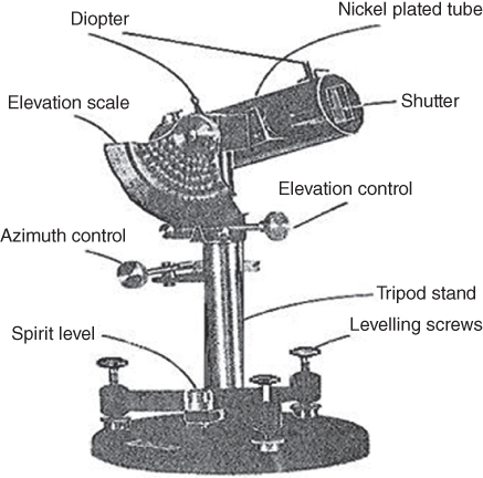
Figure 5.2 Angstrom pyrheliometer.
5.3.2 Pyranometer
The pyranometer is used to measure the total or global solar radiation incident on a horizontal surface. It is capable of measuring solar radiation in the wavelength range of about 130–3000 nm. The working principle of a pyranometer is similar to that of a pyrheliometer, except that the sensitive surface is exposed to total solar radiation. A thermoelectric pyranometer is shown in Fig. 5.3. Several pairs of thermocouples are connected in series to make a thermopile that detects the temperature difference between the black hot junction exposed to the Sun and the cold junctions which are completely shaded. The temperature difference between the hot and cold junctions is the function of radiation incident on the sensitive surface. Two concentric hemispherical glass domes cover the sensitive surface to protect it from rain and wind and also reduce the convection currents. When sunlight falls on a pyranometer, the thermopile sensor produces a proportional response typically in 30 s or less. If the sunlight is more, the sensor is hotter, and it generates a larger voltage. The thermopile is designed to be precisely linear (so a doubling of solar radiation produces twice as much current) and also has a directional response: it produces the maximum output when the Sun is directly overhead (at midday) and zero output when the Sun is on the horizon (at dawn or dusk). This is called a cosine response (or cosine correction), because the electrical signal from the pyranometer varies with the cosine of the angle between the Sun's rays and the vertical.

Figure 5.3 Thermoelectric pyranometer.
The instrument has a voltage output of approximately ![]() . If the pyranometer is provided with occulting disc to prevent direct radiation reaching to the sensitive element, it can measure the diffused radiation only. Not all pyranometers use thermopiles. Considerably cheaper and less sophisticated solar-cell pyranometers, based on light-sensitive semiconductor chips that provide approximate measurements, are also available. Their main drawback of these is that they respond only to a limited range of wavelengths. This means that a solar-cell version responds to wavelengths in a much narrower band at about 300–1100 nm (with a peak in the infrared region at around 800–1100 nm).
. If the pyranometer is provided with occulting disc to prevent direct radiation reaching to the sensitive element, it can measure the diffused radiation only. Not all pyranometers use thermopiles. Considerably cheaper and less sophisticated solar-cell pyranometers, based on light-sensitive semiconductor chips that provide approximate measurements, are also available. Their main drawback of these is that they respond only to a limited range of wavelengths. This means that a solar-cell version responds to wavelengths in a much narrower band at about 300–1100 nm (with a peak in the infrared region at around 800–1100 nm).
5.3.3 Sources of Errors in Radiation Meters
Since the pyranometer output signal is influenced by the conditions at which the measurements are made, it needs to be properly calibrated from time to time in order to give accurate measurement results. The errors in meters are introduced as the conditions at the time of application may be different from the conditions at the time of calibration. The following errors are possible:
In actual conditions, the wavelength characteristic of radiometer differs slightly for different radiometer. Observation errors therefore occur when the energy distribution of solar radiation against wavelength varies with the Sun's elevation or atmospheric conditions.
Since thermo-electromotive force of a thermopile is non-linear and the heat conductivity inside a radiometer depends on temperature, the sensitivity of these instruments varies, and an error occurs when the ambient temperature and the temperature of the radiometer are not the same.
The field of view of a pyrheliometer is somewhat larger than the viewing angle of the Sun. Errors occur when the field of view is different, as the influence from diffuse sky radiation near the Sun differs. Pyrheliometers with different fields of view may make different observations depending on the turbidity of the atmosphere.
The characteristic may also deviate, and errors may occur because of the uneven thickness, curvature or material of the glass cover.
5.3.4 Sunshine Recorder
Sunshine duration is the length of time that the ground surface receives radiation by direct sunlight, that is, sunlight reaching the Earth's surface directly from the Sun. In 2003, WMO defined sunshine duration as the period during which direct solar irradiance exceeds a threshold value of 120 W/m2. This value is equivalent to the level of solar irradiance shortly after sunrise or shortly before sunset in cloud-free conditions. It was determined by comparing the sunshine duration recorded using a Campbell–Stokes sunshine recorder with the actual direct solar irradiance.
A sunshine recorder is a device that records the duration of sunshine in hours at a given location during the course of a day. The results provide information about the weather and climate of a geographical area. Campbell–Stokes sunshine recorders and Jordan sunshine recorders have long been used as instruments to measure sunshine duration. These instruments have the advantage of having no moving parts and require no electric power. But they have a disadvantage that the characteristics of the recording paper or photosensitized paper used in them affect the measurement accuracy. Since the threshold value for the definition of sunshine is set as a direct solar irradiance of 120 W/m2, sunshine recorders using photosensors as radiation detectors are also available.
Figure 5.4 shows a Campbell–Stokes sunshine recorder. It is the most widely used sunshine recorder in the world. A homogeneous transparent glass sphere is supported on an arc and is focused so that an image of the Sun is formed on the recording paper placed in a metal bowl attached to the arc. The glass sphere is concentric to this bowl, which has three partially overlapping grooves into which recording cards for use in the summer, winter or spring and autumn are set. Three different recording cards are used depending on the season. As the Sun moves across the sky, the spot moves across the card burning a trace; when the Sun is obscured, the trace is interrupted. The length of the burn trace left on the card represents the sunshine duration. The recording card is scaled with hour marks so that the exact time of sunshine occurrence can be ascertained. Measuring the overall length of burn traces reveals the sunshine duration for that day. For exact measurement, the sunshine recorder must be accurately adjusted for planar levelling, meridional direction and latitude. From sunshine duration, the amount of monthly average of daily total solar radiation on a horizontal surface can be obtained using the following empirical relation:

where Q is the daily total amount of global solar radiation at the ground surface, ![]() is the daily extraterrestrial radiation, N is the sunshine duration,
is the daily extraterrestrial radiation, N is the sunshine duration, ![]() is the possible sunshine duration and a and b are constants for a particular location and depend on the latitude of the location. Values of a and b have been obtained for many cities in the world.
is the possible sunshine duration and a and b are constants for a particular location and depend on the latitude of the location. Values of a and b have been obtained for many cities in the world.

Figure 5.4 Campbell's sunshine recorder.
5.4 Solar Radiation on Different Surfaces
In order to determine the solar radiation on different surfaces of the Earth, it will be useful to understand certain basic definitions stated as follows.
5.4.1 Zenith and Zenith Angle
Zenith is a point directly overhead. Zenith angle ![]() is the angle between the solar incidence beam and vertical line on the horizontal surface.
is the angle between the solar incidence beam and vertical line on the horizontal surface.
5.4.2 Solar Time
Solar radiation calculations must be made in terms of solar time. The length of a solar day varies throughout the year because the Sun moves along the ecliptic at a varying rate throughout the year. It is more convenient to define time in terms of the average of local solar time. The difference between the true time and the mean time is known as Time Equation.
The time equation is written as
where ![]() is the standard longitude used for measuring the standard time of the country and
is the standard longitude used for measuring the standard time of the country and ![]() is the longitude of the observer location. The positive sign is used if the standard meridian of the country lies in the western hemisphere, and negative for eastern hemisphere. E is the correction used to take into account the variation in length of the solar day due to Earth's rotation. The value of E is normally calculated using the following equation:
is the longitude of the observer location. The positive sign is used if the standard meridian of the country lies in the western hemisphere, and negative for eastern hemisphere. E is the correction used to take into account the variation in length of the solar day due to Earth's rotation. The value of E is normally calculated using the following equation:
where ![]() , where n = day of the year, starting from January 1st.
, where n = day of the year, starting from January 1st.
5.4.3 Latitude (∅)
It is the angle made by the radial line joining the given location on Earth's surface to the centre of the Earth with the projection of line on the equatorial plane. By convention, the latitude is positive for the northern hemisphere and negative for the southern hemisphere.
5.4.4 Declination Angle (δ)
The declination angle, denoted by δ, is defined as the angle between the equator and a line drawn from the centre of the Earth to the centre of the Sun. It varies seasonally due to the tilt of the Earth on its axis of rotation and the rotation of the Earth around the Sun. It is positive when measured in the northern hemisphere. If the Earth were not tilted on its axis of rotation, the declination would always be 0°. However, the Earth is tilted by 23.45°, and the declination angle varies plus or minus this amount depending on whether the measurement is made in the northern or southern hemisphere. Only in the spring and fall equinoxes i, the declination angle is equal to 0°. The declination angle can be approximately determined from the following equation:
5.4.5 Hour Angle (ω)
The hour angle measures the time before or after solar noon in terms of 15 degrees per hour. The time after solar noon is expressed using a positive hour angle, and the time before solar noon is expressed using a negative hour angle. Therefore, at 2 h before solar noon, the hour angle is –30°, and at 2 h after solar noon, it is +30°.
5.4.6 Surface Azimuth Angle (Y)
It is the angle made on a horizontal plane between the line at due south and the horizontal projection of the normal to the inclined plane surface (collector). Due south is taken as zero, and east of south as positive, Fig. 5.5(a).

Figure 5.5 (a) Azimuth angles, (b) incidence angle.
5.4.7 Tilt Angle (β)
This is the angle between the inclined surface and the horizontal plane.
5.4.8 Angle of Incidence
The angle of incidence ![]() is the angle a ray of Sun makes with a line perpendicular to a surface (collector), as shown in Fig. 5.5(b).
is the angle a ray of Sun makes with a line perpendicular to a surface (collector), as shown in Fig. 5.5(b).
The angle of incidence can be represented by

5.4.9 Solar Radiation on an Inclined Surface
The solar collectors or solar panels are never placed in a horizontal surface [6]. These are always installed at an angle (TILTED) with the horizontal surface. It is therefore important to estimate the radiation on a tilted surface for designing and evaluating the performance of solar systems. However, in general, in national meteorological stations, global irradiance is measured only on horizontal surfaces. For determining the radiation on a tilted surface, the relation between beam radiation on the tilted surface with that on the horizontal surface ![]() is used. The daily total radiation incident on a tilted surface is composed of direct (beam)
is used. The daily total radiation incident on a tilted surface is composed of direct (beam) ![]() , ground reflected
, ground reflected ![]() and sky-diffuse
and sky-diffuse ![]() components: the total radiation on a surface arbitrary orientation can be calculated as
components: the total radiation on a surface arbitrary orientation can be calculated as
where ![]() are known as tilt factors for beam, diffused and reflected radiations.
are known as tilt factors for beam, diffused and reflected radiations.
Here ![]() is calculated as
is calculated as

where ![]() is beam radiation on the inclined surface and
is beam radiation on the inclined surface and ![]() is the radiation on the horizontal surface. If
is the radiation on the horizontal surface. If ![]() is the angle at which the plane is inclined and
is the angle at which the plane is inclined and ![]() is the zenith angle, then
is the zenith angle, then

![]() is purely geometric quantity that converts instantaneous horizontal beam radiation to beam radiation on a tilted surface. Equation (5.8) cannot be used directly for the long-term beam radiation. Normally, it should be integrated over a month to find the correct value.
is purely geometric quantity that converts instantaneous horizontal beam radiation to beam radiation on a tilted surface. Equation (5.8) cannot be used directly for the long-term beam radiation. Normally, it should be integrated over a month to find the correct value.
![]() , the tilt factor for diffused component, is given by
, the tilt factor for diffused component, is given by
where ![]() is the slope of the tilted surface.
is the slope of the tilted surface.
![]() is the tilt factor for a reflected component which comes from the ground and surrounding objects. Since
is the tilt factor for a reflected component which comes from the ground and surrounding objects. Since ![]() ,
, ![]() can be written as
can be written as

where ![]() is the reflection coefficient of the ground.
is the reflection coefficient of the ground.
5.5 Utilization of Solar Energy
Solar energy can be utilized in a number of ways. In its most simple form, the solar energy can be used to heat water during winter using solar collectors. A solar panel as shown in Fig. 5.6 is used to collect heat from the sunlight. The pipes inside the solar panel heat the water flowing through the pipes. The hot water coming out of the pipes can be used for different purposes in a house or commercially in big establishments. Similarly, solar heat energy can be used to dry grains and many other agricultural products before being stored. Otherwise, insects and fungi will make them unusable. Examples include wheat, rice, coffee, copra (coconut flesh), certain fruits and timber. In addition, concentrating collectors can be used to heat water to high temperatures for generating electricity. These are known as solar thermal systems.

Figure 5.6 Passive batch solar water heating.
In photovoltaic systems, solar cells made of semiconductor material convert solar energy directly into electrical energy. These devices produce electricity directly from electromagnetic radiation, especially light, without any moving parts.
In the photosynthesis process, the absorbed solar energy by plants is converted into chemical form of energy. In chlorophyll-containing plants, the process of photosynthesis splits water molecules (H20), releasing oxygen and storing the energy produced by that chemical reaction inside a carbohydrate molecule. The energy resident in each photon is transferred into the final organic compound product, which the plant stores as adenosine triphosphate.
Although the potential of solar energy is huge, the present market share of solar power generation is very low. Presently, developing and developed countries are steadily increasing their investments in solar power plants. The major reasons for slow deployment of solar technologies are as follows:
- The capital cost of per kW installation of solar energy is high compared to other fossil fuel and even renewable energy technologies.
- The intermittent nature of power generation means that there has to be energy storage capacity to keep the supply without interruptions. This also adds to the cost.
5.6 Solar Thermal Systems
Solar thermal systems convert solar energy into heat energy by absorbing it. These are mostly used in residential and industrial applications such as domestic water heating, heating of swimming pools, space heating, water processes for industrial heating and agricultural drying. It is also possible to convert solar thermal energy to mechanical energy through heat engines using the Rankine cycle, Stirling cycle or Brayton cycle. The mechanical energy produced can be used to drive a turbine or water lifting or for refrigeration. Solar thermal collectors are the main component of a solar thermal system. Solar energy collectors are special kind of heat exchangers that transform solar radiation energy to internal energy of the transport medium. It absorbs the incoming solar radiation, converts it into heat and transfers this heat to a fluid (usually air, water or oil) flowing through the collector [7, 8].
The solar collectors are classified as follows:
- Non-concentrating type
- Concentrating type
A non-concentrating collector has the same area for intercepting and for absorbing solar radiation. These collectors absorb both beam and diffused radiation.
Concentrating solar collector usually has concave reflecting surfaces to intercept and focus the Sun's beam radiation to a smaller receiving area, thereby increasing the radiation flux and producing high temperature. They mainly focus beam radiation as it has unique direction.
Non-concentrating type is further categorized as follows:
- i. Flat-plate collectors
- ii. Evacuated tube collector
Concentrating type is further classified as (i) non-tracking type and (ii) tracking type.
- Non-Tracking Type
- Compound parabolic collectors
- Tracking Type
- 1. Concentrating type with single-axis tracking:
- Linear Fresnel reflector (LFR)
- Parabolic trough collector (PTC)
- Cylindrical trough collector (CTC)
- 2. Concentrating type with two-axis tracking
- Parabolic dish reflector (PDR)
- Heliostat field collector (HFC)
- 1. Concentrating type with single-axis tracking:
5.6.1 Flat-Plate Collectors
Non-concentrating-type solar collectors do not have mirrors for concentration of solar light; hence, the concentration ratio is 1. Flat-plate collectors are the most widely used kind of collectors in the world for domestic solar water heating and solar space heating applications. A typical flat-plate collector is shown in Fig. 5.7. It has a black absorber surface insulated at the bottom and exposed to solar radiation. When solar radiation passes through a transparent cover and impinges on the blackened absorber surface, a large portion of this energy is absorbed by the plate and then transferred to the transport medium in the fluid tubes. The fluid delivers this heat to a thermal storage tank or use. The liquid commonly used is water; however, sometimes a mixture of water and ethylene glycol is also used. Tubes can be welded to the absorbing plate, or they can be an integral part of the plate. The liquid tubes are connected at both ends by a large-diameter header tubes. The transparent cover is used to reduce convection losses from the absorber plate by keeping the air stagnant. It also reduces radiation losses from the collector, as the glass is transparent to the short-wave radiation received by the Sun, but it is nearly opaque to long-wave thermal radiation emitted by the absorber plate (greenhouse effect). Flat-plate collectors are normally permanently fixed in position and do not have moving facility to track the Sun. The collectors face directly towards the equator, facing south in the northern hemisphere and north in the southern hemisphere. The optimum tilt angle of the collector is equal to the latitude of the location with angle variations of 10–15°, more or less depending on the application.

Figure 5.7 Flat-plate collector.
Commercial solar absorbers are made by electroplating, anodization, evaporation, sputtering and applying solar selective paints. Header pipes that are used to admit and discharge the fluid have slightly larger diameter typically 1.8–2.5 cm. The metal commonly used for absorber plate and tubes and header pipes is copper, but other metals and plastics have also been tried. In the bottom and along the side walls, thermal insulation by 2.5–8 cm thick layer of glass wool is provided to prevent heat loss.
The absorber is usually covered with one or more transparent or translucent cover sheets to reduce convective heat loss. In the absence of a cover sheet, heat is lost from the absorber as a result of not only forced convection caused by local wind but also natural convective air currents created because the absorber is hotter than ambient air.
The number of cover sheets on commercial flat-plate collectors may vary from none to three or more. Since the incoming energy is not lost by absorption or reflection by the cover sheet, collectors with no cover sheet have high efficiencies when operated at temperatures very near the ambient temperature. However, a considerable amount of the incident energy is lost in the collectors without cover at temperatures much above ambient or at low solar irradiance levels. A typical application for an uncovered flat-plate collector is for swimming pool heating, where temperatures not more than 10°C (18°F) above ambient are required.
With increase in the number of cover sheets, the temperature at which the collector can operate is increased considerably. One or two cover sheets are common, but triple-glazed collectors have been designed for extreme climates. Each added cover sheet increases the cost, but the collection efficiency at high temperatures is increased by reducing the convection loss. However, it decreases the efficiency at low temperatures because of the added absorption and reflectance of the cover.
Glass is preferred for outer cover sheets on most commercial collectors because of its superior resistance to the environment. The plastic sheet can be installed beneath the glass which protects it from the environment. Glass also does not transmit UV radiation and thus protects the plastic from UV radiation.
5.6.1.1 Thermal Performance of Collector
The performance of the solar thermal flat-plate collector depends on the amount of solar insolation absorbed by the plate. It is defined as the useful energy gain or collector efficiency. The amount of solar radiation Q received by the solar collector is
where I is the instantaneous intensity of solar radiation in W/m2 as given by Eq. (5.6), and A is the area of collector surface in m2. Since a part of this radiation is reflected back to the sky, another component is absorbed by the glazing, and the rest is transmitted through the glazing and reaches the absorber plate as short-wave radiation. A conversion factor is required to get the actual flux absorbed by the collector. Basically, it is the product of the rate of transmission of the cover and the absorption rate of the absorber. Thus, Eq. (5.11) can be written as
where ![]() is the transmissivity–absorptivity product for intensity of solar radiation incident on the collector.
is the transmissivity–absorptivity product for intensity of solar radiation incident on the collector.
As the heat is absorbed by the collector, its temperature increases, and the heat is lost to the atmosphere by convection and radiation. The rate of heat loss can be represented by the overall heat transfer coefficient ![]() as
as
where ![]() is the average temperature of the collector and
is the average temperature of the collector and ![]() is ambient temperature.
is ambient temperature.
The efficiency of the flat-plate collector can be expressed as

here ![]()

5.6.2 Evacuated Tube Collector
Conventional simple flat-plate solar collectors were developed for use in sunny and warm climates. Their benefits, however, are greatly reduced when conditions become unfavourable during cold, cloudy and windy days. The performance of flat-plate collectors is improved by minimizing the convective heat loss from the collector by placing the solar radiation absorbing surface in a vacuum. These collectors are called evacuated tube collectors. These collectors have very low overall heat loss when operated at high temperatures. This is because they are essentially single-glazed collectors with the space between the glazing and absorber evacuated, thereby eliminating the convective loss. They are the most efficient solar collectors having conversion efficiency of over 90%.
A number of designs have been developed, and some of these are commercially available. Two main types of evacuated tube collectors are (i) direct-flow evacuated tube and (ii) heat-pipe evacuated tube collectors.
5.6.2.1 Direct-Flow Evacuated Tube Collector
Direct-flow evacuated tube collectors also known as “U” pipe collectors shown in Fig. 5.8(a) have two heat pipes running through the centre of the tube. One pipe acts as the flow pipe while the other acts as the return pipe. Both pipes are connected together at the bottom of the tube with a “U-bend”, hence the name. The heat absorbing reflective plate acts as a dividing strip which separates the flow and the return pipes through the solar collector tubes. The absorber plate and the heat transfer tube are also vacuum sealed inside a glass tube providing exceptional insulation properties. The outer tube is transparent, allowing light rays to pass through with minimal reflection. Sunlight passing through an outer glass tube heats the absorber tube contained within it. The absorber can consist of either copper (glass–metal) or specially coated glass tubing (glass–glass). The glass–metal evacuated tubes are typically sealed at the manifold end, and the absorber is actually sealed in the vacuum; thus, the fact that the absorber and heat pipe are dissimilar metals creates no corrosion problems. The inner tube is coated with a special selective coating (Al–N/Al) which features excellent solar radiation absorption and minimal reflection properties. The tops of the two tubes are fused together, and the air contained in the space between the two layers of glass is pumped out. This “evacuation” of the gasses forms a vacuum, which is an important factor in the performance of the evacuated tubes. Since the fluid flows into and out of each tube, the tubes are not easily replaced. In addition, should a tube break, it is possible that all of the fluid could be pumped out of the system if a closed loop is used, or the water will flow out as in a broken pipe if an open loop is used. Direct-flow evacuated tubes can collect both direct and diffuse radiation and do not require solar tracking. However, various reflector shapes placed behind the tubes are sometimes used to usefully collect some of the solar energy, which may otherwise be lost, thus providing a small amount of solar concentration.

Figure 5.8 (a) Direct flow evacuated tube collector. (b) Heat pipe type.
5.6.2.2 Heat-Pipe Evacuated Tube Collector
In heat-pipe evacuated tube collectors shown in Fig. 5.8(b), a sealed heat pipe, usually made of copper to increase the collector efficiency at cold temperatures, is attached to a heat absorbing reflector plate within the vacuum sealed tube. The hollow copper heat pipe within the tube is evacuated of air but contains a small quantity of a low-pressure alcohol/water liquid that turns into steam when heated and rises to the top of the pipe. The top part of the heat pipe, and therefore the evacuated tube, is connected to a copper heat exchanger called the “manifold”. When the hot vapour still inside the sealed heat tube enters the manifold, the heat energy of the vapour is transferred to the water or glycol fluid flowing through the connecting manifold.
The main advantage of heat-pipe evacuated tube collectors is that there is a “dry” connection between the absorber plate and the manifold, making installation much easier than with direct-flow collectors. In addition, in the event of an evacuated tube cracking or breaking and the vacuum becoming lost, the individual tube can be exchanged without dismantling the entire system.
Evacuated tube collectors heat to higher temperatures and provide considerably more solar yield per square metre compared flat panels. However, they are more expensive than flat panels, but require less cost to repair in the event of damage. Evacuated heat tubes perform better than flat-plate collectors in cold climates because they only rely on the light they receive and not the outside temperature.
The efficiency of the evacuated tube solar collector depends mainly on the angle of inclination which should be approximately the latitude of the location. The collectors, however, cannot be installed at less than 20° angle. Evacuated tube solar collectors with internal adjustable collector surfaces allow this type of collector to be installed at angles ranging from 20° to 90°. The collector surfaces inside the evacuated tubes are set to the optimal angle during the installation. An evacuated tube collector is shown in Fig. 5.9.
5.6.3 Parabolic Collectors
Concentrating-type solar collectors are generally used along with a tracking mechanism for applications where high temperatures are required. These are devices that optically reflect and focus the incident solar energy onto a small receiving area. As a result of this concentration, the intensity of the solar energy is magnified. Because in this the temperature of the receiver can approach several hundred degrees.

Figure 5.9 Evacuated tube collector.
The compound parabolic collector is a solar collector which is stationary and has no tracking system. This is a non-imaging concentrator that concentrates light rays and has the capability of reflecting to the absorber all of the incident radiation within wide limits.
The basic shape of the compound parabolic concentrator (CPC) is illustrated in Fig. 5.10. The name, compound parabolic concentrator, derives from the fact that the CPC is comprised of two parabolic mirror segments with different focal points. The focal point parabola 1 lies on parabola 2, whereas the focal point of parabola 2 lies on parabola 1. The two parabolic surfaces are symmetrical with respect to reflection through the axis of the CPC.
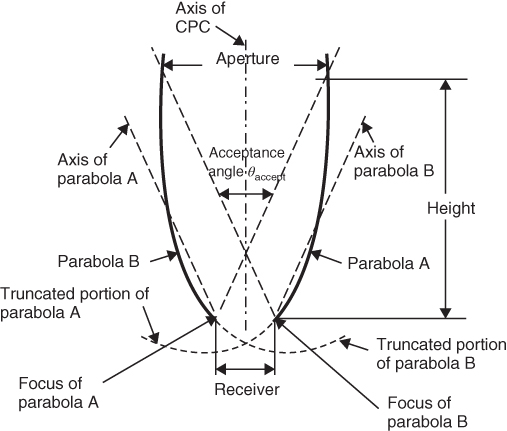
Figure 5.10 Compound parabolic dish collector.
By using multiple internal reflections, any radiation that is entering the aperture, within the collector acceptance angle, is absorbed by the surface located at the bottom of the collector.
In particular, a working fluid at 500°C can drive a conventional heat engine to produce mechanical work and can also be used to produce electricity. The absorber can take a variety of configurations. But generally, tubes are used which are selectively coated and attached to the bottom, or it can be cylindrical as shown in Fig. 5.10. In the CPC shown in Fig. 5.10, the lower portion of the reflector is circular, while the upper portions are parabolic. As the upper part of a CPC contributes little to the radiation reaching the absorber, it is usually truncated, thus forming a shorter version of the CPC, which is also cheaper. CPCs are usually covered with glass to avoid dust and other materials from entering the collector and thus reducing the reflectivity of its walls. It is possible to attach a tracking system with CPC. In stationary type, radiation will only be received for the duration when the Sun is within the collector acceptance angle.
5.6.4 Linear Fresnel Reflector (LFR)
Linear Fresnel reflector is a concentrating-type solar collector with single-axis tracking mechanism. In 1822, a French physicist named Augustin Fresnel invented a lens of thin (low-weight and low-volume) for short focal length. Its first application was in lighthouses: to focus light horizontally and make it visible over a greater distance.
The principle of LFC is to concentrate the sunlight on an absorber tube that is fixed on a linear tower. However, unlike in parabolic trough collectors (PTCs), this is done by several linearly aligned mirrors as shown in Fig. 5.11. Each mirror with a characteristic curvature directs the beam radiation on to the absorber tube. In addition, each solar mirror is flat instead of expensive parabolic mirrors used in parabolic trough collector. The entire optical system is enclosed in a sealed glazed casing. This concentrated energy is transferred through the absorber into the turbines for power generation. For generating sufficient power, many towers are required.
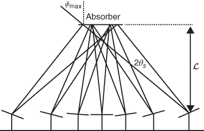
Figure 5.11 Linear Fresnel reflector.
One problem with LFR system is avoidance of shading and light blocking by adjacent reflectors which means larger spacing between reflectors.
Compact linear Fresnel reflector (CLFR) technology is a new configuration of the Fresnel reflector field that overcomes the problem of reflector spacing [9]. Traditional LFR technology design is based around one absorber tower. The classical linear Fresnel system has only one linear receiver, and therefore, there is no possibility of changing the direction of orientation of a given reflector. However, if the size of the field is large, which is normal for generating electricity in the megawatt class, it is reasonable to assume that there will be many linear receivers in the system. If they are close enough, then individual reflectors have the option of directing the reflected solar radiation to at least two receivers. This additional possibility in reflector orientation provides the means for much more densely packed arrays and lower absorber tower heights, because patterns of alternating reflector orientation can be set up such that closely packed reflectors can be positioned without shading and blocking.
The avoidance of large reflector spacing and tower heights is an important cost issue when the cost of ground preparation, array substructure cost, tower structure cost, steam-line thermal losses and steam-line cost are considered.
5.6.5 Parabolic Trough Collector (PTC)
Figure 5.12 shows a typical parabolic trough collector (PTC), which is basically composed of a parabolic-trough-shaped concentrator that reflects direct solar radiation onto a metal black tube located in the focal line of the parabola. Since the collector aperture area is bigger than the outer surface of the receiver tube, the direct solar radiation is concentrated. The dish structure must fully track the Sun to reflect the beam into the thermal receiver. The concentrated radiation reaching the receiver tube heats the fluid that circulates through it, thus transforming the solar radiation into thermal energy in the form of sensible heat of the fluid. This fluid can be efficiently heated up to 400°C. Since a PTC is an optical solar concentrator, it has to be positioned at every moment in accordance with the Sun's position (i.e. Sun's vector) so that the incoming direct solar radiation is reflected onto the receiver tube. It is sufficient to use single-axis tracking of the Sun, and long collector modules can be used.

Figure 5.12 Parabolic trough collector.
The collector can be oriented in the east–west direction, and tracking is from north to south. If the collector is oriented in the north–south direction, the tracking is in the east–west direction.
Parabolic trough technology is the most mature technology available for solar heating to about 400°C. The concentration ratio of a PTC is the ratio between the collector aperture area and the total area of the absorber tube. Usual values of the concentration ratio are about 20, although the maximum theoretical value is in the order of 70. High concentration ratios are associated with higher working temperatures.
A typical solar field with PTCs is composed of a number of parallel rows of collectors, with several collectors connected in series within every row. The number of PTCs connected in series within every row depends on the temperature required, while the number of rows connected in parallel depends on the required thermal output power of the system.
The selection of the working fluid for a solar field with PTCs is a very important. Thermal oil is commonly used in parabolic trough collectors for temperatures above 200°C, because if normal water is used, these operation temperatures would produce a high pressure inside the receiver tubes. This high pressure would require stronger joints and piping and thus increases the price of the collectors and complete solar field.
5.6.6 Cylindrical Trough Collector (CTC)
CTCs are similar to parabolic trough collector and are made by bending a sheet of a reflective material into a cylindrical shape. The receiver tube is covered with another glass tube (to reduce heat loss) and is placed at the focal line. When the collector is facing the Sun, some rays that hit the reflector surface are reflected on the receiver tube. The receiver tube is blackened at the outside surface to increase absorption. The reflected rays heat up the working fluid which is flowing in the receiver tube. For efficient performance, CTCs have to face the Sun at all time; hence, they are usually equipped with a single-axis tracking system. This means that at different times of the day, the reflector surface will have different orientations. Reflector orientation can have a significant impact on the structure and thermal efficiency of the collector.
5.6.7 Parabolic Dish Reflector
Large solar mirror collectors are a major subsystem of many solar energy systems, particularly for solar thermal generators. Thermal systems may use many collectors covering large sites. Parabolic dish concentrators offer the highest thermal and optical efficiencies of all the current concentrator options. A parabolic dish reflector, shown schematically in Fig. 5.13, uses parabolic-dish-shaped mirrors to focus the incoming solar radiation onto a receiver positioned at the focal point of the dish. These concentrators are mounted on active tracking systems to follow the Sun. It tracks the Sun in two axes. The dish structure must fully track the Sun to reflect the beam into the thermal receiver, and hence, the shape of the parabola needs to be precise. In order to focus the solar energy into the collector all the time, tracking mechanisms similar to the ones used in a single-tracking system are employed in double so that the collector is tracked in two axes. The receiver absorbs the radiant solar energy, and the fluid in the receiver is heated to high temperatures around 750°C.

Figure 5.13 Parabolic dish.
This fluid is then used to generate electricity in a small Stirling or Brayton cycle engine attached to the receiver. Parabolic dish systems are the most efficient of all solar technologies and can have efficiency of about 25%. The heat transfer medium usually employed as the working fluid for an engine is hydrogen or helium. Alternate thermal receivers are heat pipes wherein the boiling and condensing of an intermediate fluid are used to transfer the heat to the engine. The heat engine system takes the heat from the thermal receiver and uses it to produce electricity, using an engine generator coupled directly to the receiver, or it can be transported through pipes to a central power-conversion system. Because the receivers are distributed throughout a collector field, as parabolic troughs, parabolic dishes are often called distributed receiver systems.
The main use of this type of concentrator is for parabolic dish engines. A parabolic dish engine system is an electric generator that uses sunlight instead of crude oil or coal to produce electricity. The main parts of this system are the solar dish concentrator and the power conversion unit.
The advantages of this technology are as follows:
- The high fluid temperature obtained leads to high conversion efficiency of solar power to electricity.
- The Stirling engine system can be used either as a relatively small distributed power source, or by combining a lot of the units. MW levels of electricity can be generated.
- The Stirling engine system requires a very small quantity of water as the engine is air cooled. Condenser cooling normally required in steam power stations is not required.
5.6.8 Heliostat Field Collector (HFC)
Central receiver concentrating solar power plants offer significant performance advantages over line-focus systems. For extremely high inputs of radiant energy, a multiplicity of flat mirrors, or heliostats, using altazimuth mounts, can be used to reflect their incident direct solar radiation onto a common target as shown in Fig. 5.14. Central receiver consists of the following:
- Solar concentrator (heliostat field)
- Receiver
- Storage system
- Power generator

Figure 5.14 Heliostat.
The reflecting element of a heliostat is typically a thin, back (second) surface, low-iron glass mirror. This heliostat is composed of several mirror module panels rather than a single large mirror. The thin glass mirrors are supported by a substrate backing to form a slightly concave mirror surface. Individual panels on the heliostat are also canted towards a point on the receiver. The heliostat focal length is approximately equal to the distance from the receiver to the farthest heliostat. Since the solar receiver is located in a fixed position, the heliostats must track the Sun. The mirrors are therefore mounted on individual frames that are tipped up and down and rotated east to west by small motors similar to those used in electric clocks. These motors are controlled by a computer which determines the position of each heliostat and directs the motors to position them so that its reflection hits the receiver throughout the year according to position of the Sun. Subsequent “tuning” of the closer mirrors is possible.
These are also known as central receiver systems. HFC has a large potential for mid-term cost reduction of electricity generation compared to parabolic trough technology [10]. The basic difference between the central receiver concept of collecting solar energy and the trough or dish collectors is that in this case, all of the solar energy collected in the entire field is transmitted optically to a small central collection region, instead of being piped around a field as hot fluid. Because of this characteristic, central receiver systems are characterized by large power levels (1–500 MW) and high temperatures 540–1000°C.
Plants with large-scale storage capability used molten nitrate as working fluids instead of steam and water in small plants. However, the high cost of the heliostat field remains a barrier to the widespread adoption of such plants.
5.7 Application of Solar Energy
Major applications of solar thermal energy in industrial and commercial sectors are as follows:
- Hot water usage for bathing and washing
- Pre-heated water up to 80°C to boilers
- Pasteurization, condensation and cleaning in milk dairies
- Drying and tanning in leather process industries
- Degreasing and phosphating in metal finishing industry
- Resin emulsification in the polymer industry
- Drying in food, wood, livestock and pharmaceutical industry
- Swimming pool water heating and so on
- Electric power generation
- Desalination of water
Solar energy can also be used in air conditioning and refrigeration.
5.7.1 Solar Water Heating
Solar energy can be used to heat liquids to low temperature of less than 80°C for domestic and service hot water [11, 12]. Most of the solar water heaters are used for domestic purpose only. When no pumping or blowing is involved, the solar system is known as passive. If the solar heat is collected in a fluid, usually water or air, which is then moved by pumps or fans for use, the solar system is said to be active.
The main part of a solar heating system is the collector, where solar radiation is absorbed, and energy is transferred to the fluid. Collectors used in water heating are either flat-plate or evacuated tube collectors.
5.7.2 Passive Systems with Thermosiphon Circulation
At the heart of a solar thermal system is the solar collector. It absorbs solar radiation, converts it into heat and transfers useful heat to the solar system. There are several different design concepts for collectors: besides simple absorbers used for swimming pool heating, more sophisticated systems have been developed for higher temperatures, such as integral storage collector systems, flat-plate collectors, evacuated flat-plate collectors and evacuated tube collectors.
Thermosiphon systems, shown schematically in Fig. 5.15, heat potable water or any other fluid and use natural convection to transport it from the collector to storage. For storing water overnight or on cloudy days, a storage tank is needed. The principle of the thermosiphon system is that cold water has a higher specific density than warm water and so, being heavier, will sink down. Since the driving force is only a small density difference, larger than normal pipe sizes must be used to minimize pipe friction. A thermosiphon system's storage tank must be positioned well above the collector; otherwise, the cycle can run backwards during the night, and all the water will cool down. Therefore, the collector is always mounted below the water storage tank, so that cold water from the tank reaches the collector via a descending water pipe. If the collector heats up the water, the water rises again and reaches the tank through an ascending water pipe at the upper end of the collector. The cycle of tank–water pipe–collector ensures the water is heated up until it achieves an equilibrium temperature. The consumer can then make use of the hot water from the top of the tank, with any water used being replaced by cold water at the bottom. The collector then heats up the cold water again. Due to higher temperature differences at higher solar irradiances, warm water rises faster than it does at lower irradiances. Therefore, the circulation of water adapts itself almost perfectly to the level of solar irradiance. Furthermore, the cycle does not work properly at very small height differences. In regions with high solar irradiation and flat roof architecture, storage tanks are usually installed on the roof. Thermosiphon systems operate very economically as domestic water heating systems, and the principle is simple, needing neither a pump nor a control. However, thermosiphon systems are usually not suitable for large systems, that is, those with more than 10 m2 of collector surface. Furthermore, it is difficult to place the tank above the collector in buildings with sloping roofs, and single-circuit thermosiphon systems are only suitable for frost-free regions.

Figure 5.15 Solar thermosiphon heating system.
The main disadvantage of thermosiphon systems is that they are tall units, which makes them aesthetically unattractive. Usually, a cold water storage tank is installed on top of the solar collector, supplying both the hot water and the cold water needs of the house, thus making the collector unit taller. Additionally, extremely hard or acidic water can cause scale deposits that clog or corrode the absorber fluid passages. For direct systems, pressure-reducing valves are required when the city water is used.
5.7.3 Integrated Collector Storage Systems (Passive)
An integrated collector storage system combines collection and storage of thermal energy in a single unit. The basic configuration of these systems is that there is a tank or a set of interconnected tanks with their exposed surfaces as energy absorbing surfaces enclosed in an insulated box with a transparent cover on the top. In the morning, water is poured into these tanks which are heated by the Sun during daytime. The hot water moves to the top of tank. The hot water is drawn from the top of the tank, and the cold make-up water enters the bottom of the tank on the opposite side.
5.7.4 Active Solar Systems
Active solar systems are ideal for heating in hotels, hospitals, apartments, dormitories and other commercial applications. In contrast to thermosyphon systems, in active solar systems, an electrical pump can be used to move water through the solar cycle of a system by forced circulation. Collector and storage tank can then be installed independently, and no height difference between the tank and the collector is necessary.
There are two types of active solar heating systems:
- 1. Direct circulation (open-loop) systems
- 2. Indirect circulation (closed-loop) systems
5.7.4.1 Direct Circulation Systems
Direct circulation systems are most suitable for homes in climates where the temperature rarely dips below the freezing point. Direct circulation systems use pumps to circulate potable water through the collectors. These systems are appropriate in areas that do not freeze for long periods and do not have hard or acidic water. These systems may require a recirculation freeze protection (circulating warm tank water during freeze conditions), and this in return requires electrical power for the protection to be effective. An open-loop system operates at atmospheric pressure. A pool uses this method as it is generally not operated in freezing months.
In direct circulation systems, the solar collector is separate from the storage cylinder and the potable water is directly heated in the solar collector. It consists of a solar collector, a circulation pump and a combined preheat tank and backup heating system. The water that will be used as domestic hot water is circulated directly into the collectors from the storage tank.
There are two types of direct systems – drain-down and re-circulating. In both systems, a controller will activate a pump when the temperature in the collectors is higher than the temperature in the storage tank. The drain-down system includes a valve that will allow the water in the collector loop to drain into a reservoir tank when the pumps stop when the outdoor temperature reaches 38°. Drain-back systems must be carefully installed to ensure that the piping always slopes downwards, so that the water will completely drain from the piping. When the temperature is higher than 38° and the collectors are hotter than the storage tank, the valve allows the system collectors to refill, and the heating operation resumes. The re-circulating system will pump heated water from the storage tank through the collectors when the temperature drops to 38 degrees.
These two systems have serious drawbacks. The cycling of air and water in a drain-down system collector as a result of periodically draining down (thereby emptying the collectors) can cause a buildup of mineral deposits in the collectors and reduce their efficiency. The re-circulating system circulates buildup from potable water heated from the storage tank through collectors during potential freeze conditions and effectively cools the water (wasting energy).
5.7.4.2 Indirect Circulation (Closed-Loop) Systems
It uses a heat transfer fluid (water or a diluted anti-freeze fluid) to collect heat and a heat exchanger to transfer the heat to the potable water indirectly. Heat exchangers transfer the heat from the heated fluid to the potable water (or other fluid). Some indirect systems have “overheat protection” by-pass which removes the heat that cannot be used. This protects the collector and the glycol fluid from becoming super-heated when the load is low and the solar intensity of incoming solar radiation is high. The heat transfer fluid is usually a glycol–water mixture with the glycol concentration depending on the expected minimum temperature. The glycol is usually food-grade propylene glycol because it is non-toxic. This system is typically used in hot water heating and radiator or in floor home/commercial heating. Because the system is closed to the atmosphere, pressure can build up as the temperature rises. Such systems will incorporate pressure relief valves and solar expansion tanks for safety purposes.
An indirect system that exhibits effectiveness, reliability and low maintenance is the drain-back system (see Fig. 5.16). The drain-back system typically uses distilled water as the collector circulating fluid. The collectors in this system will only have water in them when the pump is operating. This means that in case of power failure as well as each night, there will be no fluids in the collector that could possibly freeze or cool down and delay the start-up of the system when the Sun is shining. The fluids that are circulated into the collectors are separated from the heated water that will be used in the home by a double-walled heat exchanger. A heat exchanger is used to transfer the heat from the fluids circulating through the collectors to the water used in the home. The heat exchangers should be double-walled to prevent contamination of the household water. The heat exchanger may be separate from the storage tank or built into it. The controller in these systems will activate the pumps to the collectors and heat exchanger when design temperature differences are reached.

Figure 5.16 Drain-back hot water system.
This system is very reliable and widely used. The main requirement is that the collectors must be mounted higher than the drain-back tank/heat exchanger. This may be impossible to do in a situation where the collectors are to be placed on the ground. An indirect or direct system can be used for heating swimming pools and spas.
5.7.5 Air Heating Systems
Most solar air heaters work on the same principle as a greenhouse wherein sunlight is converted to heat within a glass or plastic-covered enclosure. The heat is then trapped in the enclosure by the glass or plastic. Solar heating is an economical way for persons to augment the heating of homes and other buildings. Solar air heating systems absorb thermal energy from direct sunlight to heat air; this heated air can then be circulated through buildings to provide heat. Heating domestic water often constitutes a large part of the household energy bill, and designing a solar air collector to help offset this expense is a viable option. Air heating systems built for both space and domestic water heating are useful year-round and not just during the winter space-heating season.
Systems that use air to heat water need an air-to-water heat exchanger. These are indirect water heating systems that circulate air via ductwork through the collectors to an air-to-liquid heat exchanger. In the heat exchanger, heat is transferred to the potable water, which is also circulated through the heat exchanger and returned to the storage tank. Normally, double storage tank type system is used, because air systems are mostly used for domestic hot water heating.
Air from inside the house is drawn by a fan into a series of channels in a space behind the absorber where it is heated by the hot absorber plate. The heated air is then utilized for process in the home directly. Excess heat is stored in a storage medium (such as rocks) so the heat will be available during the night when solar heating is not available.
A simple controller is used to turn on the fan(s) in this type of system. The controller uses sensors in the collector to activate the system when it is hotter in the collector than in the house interior or storage medium.
Air collectors can be mounted vertically on the south wall of a building if used for space heating only. In that location, properly designed overhang will prevent them from heating up in the summer.
Air collectors are more practical in climates with longer and colder winters. The investment in storage systems for air collectors is substantial. The use of air collectors to add heat into the house directly can be readily achieved with properly oriented windows in the area.
5.8 Solar Thermal Power Generation
Solar energy is being used worldwide in solar thermal power plants with a total capacity of about 2.5 GW currently in operation; about 1.5 MW is currently under construction. These plants are particularly suitable for generating electricity in regions with high direct irradiation. Concentrating solar power plants concentrate solar rays to heat a fluid, which then directly or indirectly runs a turbine and an electricity generator. Concentrating the Sun's rays allows for the fluid to reach working temperatures high enough to ensure fair efficiency in turning the heat into electricity, while limiting heat losses in the receiver. This can supplement or completely replace fossil-fuel-operated power plant. The collectors are required to track the Sun in order to achieve a sufficient concentration. The sunlight is concentrated by mirrors that bundle the light onto a heat exchanger, which transfers the absorbed energy to a heat transfer fluid.
At the moment, the collected thermal energy is predominantly transformed into electricity in steam power plants. These are suitable for capacity sizes from 10 MW upwards and for temperatures of up to about 600°C and can be coupled with parabolic trough, linear Fresnel and solar tower systems. Two common designs of CSP plants – parabolic troughs and power towers – concentrate sunlight onto a heat transfer fluid (HTF), which is used to drive a steam turbine. Stirling engines are suitable for smaller capacities up to several tens of kilowatts, which are typical for dish concentrators. Gas turbines can be used for larger capacities and higher temperatures.
In order to use solar energy for reliable power generation, solution to the problem for reduced or curtailed energy production when the Sun sets or is blocked by clouds must be found [13]. Thermal energy storage (TES) can provide a workable solution to this challenge. Thermal energy storage can be used to provide electric supply generation in the night and to provide backup energy during periods with reduced sunlight caused by cloud cover. Since 2006, plants have been built with thermal storage systems into CSP plants, almost exclusively using sensible heat storage in a mixture of molten salts. The concept of thermal storage is simple: throughout the day, excess heat is diverted to a storage material (e.g. molten salts). When production is required after sunset, the stored heat is released into the steam cycle and the plant continues to produce electricity.
Adding TES provides several advantages to a CSP plant. First, unlike a plant without storage that must sell electricity when solar energy is available, a CSP plant with TES can shift electricity production to periods of highest prices. Second, plant with TES may completely replace a conventional power plant as opposed to just supplementing its output. Finally, the dispatch ability of a CSP plant with TES can provide high-value ancillary services such as spinning reserves.
5.9 Desalination of Water
Desalination is the process of removing salt and other minerals from saline water mainly obtained from the sea. The desalination recovery ratio is the ratio of the desalinated water volume to the seawater volume. The energy cost is 0.86 kWh/m3 for conversion of seawater with saline content of 34,500 ppm at a temperature of 250°C.
Desalination processes have been used for many decades, but their high-energy requirement and, therefore, their prohibitive costs have prevented their widespread adoption across countries, However, because of the necessity, many of the countries in the Middle East make extensive use of desalination for freshwater. For example, the Kingdom of Saudi Arabia and the Gulf States are currently almost completely dependent on desalination for much of their water needs, and this incurs considerable use of non-renewable energy.
Thermal desalination involves distillation processes where saline feed water is heated to vaporize, causing freshwater to evaporate and leave behind a highly saline solution, namely the brine. Freshwater is then obtained from vapour cooling and condensation. The Multi-stage flash (MSF) process is divided into sections or stages. Saline water is heated at the boiling temperature between 90 and 110°C, with a decreasing pressure through the stages. Part of the water quickly vaporizes at each stage while the rest continues to flow through the following stages (Fig. 5.17).

Figure 5.17 Desalination of water.
Concentrated solar–thermal desalination plants are solar power plants that make use of solar radiation primarily in the infrared (IR) range to power the desalination of saltwater to freshwater. The most modern solar–thermal desalination systems generally produce concentrated heat energy, which is used to create pressurized steam, which is used to power reverse osmosis desalination systems.
5.10 Steam Pressurization Systems Using Heat Energy
The technology for producing pressurization from heat energy is very well established due to its use many prior industrial applications. For example, in a steam engine, the pressure vessel of the steam engine boiler is heated from externally applied heat energy, and as a consequence, the steam within the pressure vessel is pressurized (in the case of a steam engine, this pressurized steam is subsequently released to generate mechanical energy). As another example, for solar–thermal–electrical generators, the pressure vessel is heated from heat energy obtained from a solar concentrator. Both of these example steam pressurization systems also include a cooling cycle to cool and return the steam. In contrast, for solar desalination applications of interest here, the pressurization to drive desalination can make use of a pressure vessel that is heated using heat energy obtained from a solar concentrator; the pressurized steam is then released to drive the (reverse osmosis) desalination process. Again, the system also needs to include a cooling cycle to cool and return the steam. As noted earlier, saltwater reverse osmosis desalination requires only moderate pressure of approximately 55 bar, and such use of conventional heated pressure vessels can be used to achieve this pressure.
5.11 Summary
Solar energy is available in abundance and can be utilized for various purposes resulting in less pollution. In this chapter, the solar radiation and its spectral distribution are described. The instruments for measurement of solar radiation are important for designing solar systems. The solar power collectors with various designs as used in the solar energy application have been described in detail. Finally, the applications of solar energy in heating and cooling are discussed.
References
- 1 Boyle, G. (ed.) (2012) Renewable Energy - power for a sustainable future, Third edn, Oxford university Press.
- 2 Duffie, J.A. and Beckman, W.A. (1991) Solar Energy of Thermal Process, second edn, Wiley & Sons, New York.
- 3 IEA (2004) World Energy Outlook 2004, International Energy Agency, Paris, IEA/OECD.
- 4 Perez, R. et al. (1990) Modeling Daylight Availability and Irradiance Components from Direct and Global Irradiance. Solar Energy, 44 (5), 271–289.
- 5 Paulescu, M. et al. (2013) Weather Modelling and Forecasting of PV Systems Operation, Chapter 2, Springer.
- 6 Mehleri, E.D. et al. (2010) Determination of the optimal tilt angle and orientation for solar photovoltaic arrays. Renewable Energy, 35 (11), 2468–2475.
- 7 Mills, D. (2004) Advances in solar thermal electricity technology. Solar Energy, 76, 19–31.
- 8 Soteris, K.A. (2004) Solar thermal collectors and applications. Progress in Energy and Combustion Science, 30, 231–295.
- 9 Mills, D.R. and Morrison, G.L. (1999) Compact linear Fresnel reflector solar thermal power plants. Solar Energy, 68, 263–283.
- 10 Schell, S. (2011) Design and evaluation of Esolar's heliostat field. Solar Energy, 85, 614–619.
- 11 Norton, B. (1992) Solar Energy Thermal Technology, Springer, London.
- 12 Kreider, J.F. (1982) The Solar Heating Design Process, McGraw-Hill, New York.
- 13 Madaeni, S.H., Siosanshi, R. and Denholm, P. (2012) Estimating the capacity value of concentrating solar power plants with thermal energy storage: a case study of the southwestern United States. IEEE Transaction on Power System, 27 (2), 1116–1124.