
7
The Three Layers of Cyber‐Physical Systems
This chapter introduces the three layers that constitute every cyber‐physical system (CPS). Our aim is to articulate the concepts that were presented in the first part of this book in order to construct a scientific theory of CPSs that are systematically characterized by physical, data, and decision layers, as well as the necessary processes that define cross‐layer relations. One important remark before we start: there are several layered architectures to analyze and develop specific CPSs, such as industrial production systems [1, 2] and power grids [3], but our proposal is very different. Those existing layered models focus on practical questions of particular cases, offering flexibility and a unified lexicon to assess and deploy such CPSs. In this book, our objective is to characterize what constitutes CPSs as such, not restricting our study to specific cases. In fact, different CPSs will be analyzed in Part III as realizations of the general theory proposed here. The approach taken here extends the ideas introduced in [4–7].
7.1 Introduction
In the first chapter, we provided a broad definition of CPSs, which was put forth by the standardization organization NIST. This chapter will finally state our proposed definition of CPSs. The idea is to characterize a typical CPS following the concept of “system” as defined in Chapter 2, indicating that, to be a CPS, it must be composed of a physical system from where data are collected to be processed and then used in a decision‐making process that will determine actions that have the potential to modify the physical system. Therefrom, we can define the physical, data, and decision layers of CPSs, and also measuring/sensing, informing, and acting cross‐layer processes. In what follows, we will formalize this definition.
This definition states the reasons why CPSs ought to be studied as a specific object that cannot be reduced to other existing theories, such as system dynamics, control theory, information theory, computer sciences, or game theory. Following the concepts introduced in the previous chapters, a full account of a given CPS needs to consider how data are acquired from physical processes, which are related to specific observable attributes, to be then transmitted, stored, and manipulated using information and communication technologies (ICTs). These processed data should then become informative about the operation of the system under consideration allowing for informed decision‐making processes about interventionist actions to guarantee its functioning. Following the approach introduced in [4] and further developed in [7], the simplest theoretical model of every CPS must consider three constitutive layers and three cross‐layer processes. The following proposition defines them.
This proposition presents how every CPS is organized within its boundaries in the sense that was defined in Chapter 2. It is important to note that CPSs have relations with the external world, including other systems and the environment in general. These external conditions can be associated with any layer. Remember that Proposition 7.1 refers to CPSs in general, but the aforementioned relations ought to be defined for their particular realizations.
In addition, CPSs involve more components than previously described in Chapter 2, where we defined the structural, operating, and flow components. For the CPS, we need to extend these to explicitly incorporate measuring components, computing components, and communication components that are necessary to construct CPSs. To illustrate how to analyze a particular CPS using Proposition 7.1 as well as the types of components that we just introduced, we will revisit Example 3 from Chapter 2 as follows.
Roughly speaking, the conceptual turbine that we just presented is a CPS because the cyber domain constituted by informative data is necessary to its successful physical operation, namely converting wind into electricity. The cyber domain is also supported by physical devices – the measuring, computing, and communication components. However, the cyber domain itself is constituted by meaningful data and logical relations, both related to semantics. The regulation of the physical process of energy conversion is then mediated by potentially informative data that are the basis of operation decisions and the respective interventions. In the following sections, we will present in more details the three layers of CPSs and the respective cross‐layer processes.
7.2 Physical Layer, Measuring, and Sensing Processes
A presupposition of any engineering conceptual system is that it has the potential to be materially deployed. The wind turbine exemplified in the previous section is designed aiming at its physical construction in the future. Cars, highways, bikes, microwave ovens, brain–computer interfaces, televisions, wireless network base stations, mobile phones, and power grids have a material existence, and thus, their behavior at this layer can be evaluated by physical laws. The level of details is dependent on the specific application. For an incandescent lamp, the simple characterization of electric circuits based on Ohm's law is enough. If the system under consideration is an electronic circuit with transistors, the design would require a more detailed analysis of the electric field in different materials. Currently, emerging topics of quantum computing [8] and biological implementation of logical gates [9] consider, in their own way, different levels of characterization based on fundamental physical laws.
The physical layer of CPSs refers to those aspects that are governed by direct physical relations, which are different from the logical relations that are mediated by data. Figure 7.1 illustrates a simple representation of a direct current electric circuit whose full description is derived from the well‐known Ohm's law: ![]() (i.e. the voltage between two given points is equal to the current that passes through a conductor between these two points times its electric resistance); the dissipated power by the resistor is computed as
(i.e. the voltage between two given points is equal to the current that passes through a conductor between these two points times its electric resistance); the dissipated power by the resistor is computed as ![]() . As indicated by the figure, there is a switch before each resistor, which could be on (closed) or off (opened). In this case, the circuit could have different physical topologies that lead to different system behavior, which will be presented next. For the calculations, the values of the resistances are the same
. As indicated by the figure, there is a switch before each resistor, which could be on (closed) or off (opened). In this case, the circuit could have different physical topologies that lead to different system behavior, which will be presented next. For the calculations, the values of the resistances are the same ![]() , and the source produces a constant voltage
, and the source produces a constant voltage ![]() . We are interested in the power dissipated by each resistor
. We are interested in the power dissipated by each resistor ![]() ,
, ![]() , and
, and ![]() , as well as by the whole circuit
, as well as by the whole circuit ![]() .
.
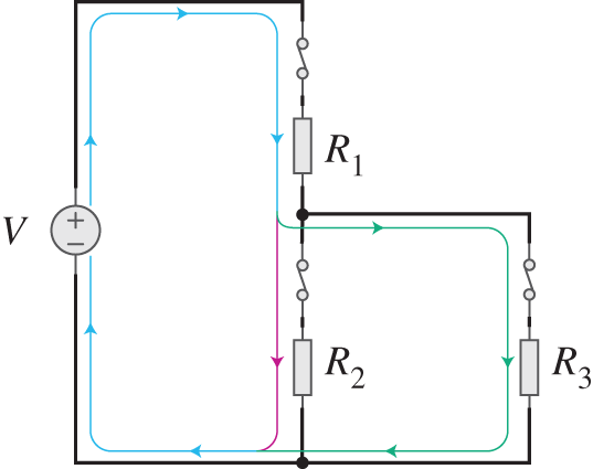
Figure 7.1 Electric circuit with direct current: a constant voltage source  and three resistors
  ,
,  , and
, and  .
.
Case 1: The switch of ![]() is off, or the switches of
is off, or the switches of ![]() and
and ![]() are off. In both cases, the equivalent resistance is
are off. In both cases, the equivalent resistance is ![]() so that
so that ![]() . Without current, no power is dissipated (“consumed”) by the resistors. Then,
. Without current, no power is dissipated (“consumed”) by the resistors. Then, ![]() .
.
Case 2: The switch of ![]() is on, and only one of the other switches from either
is on, and only one of the other switches from either ![]() or
or ![]() is off. In this scenario, the resistors will be connected in series and the equivalent resistance is
is off. In this scenario, the resistors will be connected in series and the equivalent resistance is ![]() . This will result in
. This will result in ![]() . Since the resistors have the same resistance, the power dissipated by each resistor is
. Since the resistors have the same resistance, the power dissipated by each resistor is ![]() , and
, and ![]() and
and ![]() , or
, or ![]() and
and ![]() . The total dissipated power is
. The total dissipated power is ![]() .
.
Case 3: All the three switches are on. In this scenario, resistors ![]() and
and ![]() are connected in parallel, resulting in an equivalent of
are connected in parallel, resulting in an equivalent of ![]() , which is connected in series with
, which is connected in series with ![]() . This will lead to an equivalent
. This will lead to an equivalent ![]() . This will result in a current in the equivalent circuit
. This will result in a current in the equivalent circuit ![]() and a total power dissipated
and a total power dissipated ![]() . The current passing through
. The current passing through ![]() is
is ![]() , and thus,
, and thus, ![]() . Then,
. Then, ![]() . As
. As ![]() and
and ![]() have the same value,
have the same value, ![]() .
.
These equations unambiguously determine the behavior of the electric circuit. One important aspect here is to explicitly mention that these relations presume the electric phenomena under investigation to be measurable. Consider that the voltage in the source is the input of this circuit, and the output of the system is the dissipated power, which is measured in the three resistors. Figure 7.2 numerically exemplifies cases 2 and 3 considering an arbitrary setting.
In this case, we consider a perfect measuring process based on a conceptual example. In real‐world devices there are many problems in measuring (and sensing), such as poor calibration, interference, and noise. Regardless of those challenges, measuring and sensing processes are necessary to map physical processes into the data. This is what is usually called data acquisition.
In CPS, data acquisition is almost always digital, not analog. In this case, the data acquisition is always quantized in time (not continuous), being it periodic (i.e. acquire new data sample every 10 seconds), event‐driven (i.e. acquire new data sample when a predetermined event happens, e.g. the dissipated power is above a threshold value), or a hybrid between both. The acquired data are hence stored, transmitted, and processed in bits, which are constitutive of the data layer, which will be discussed next.
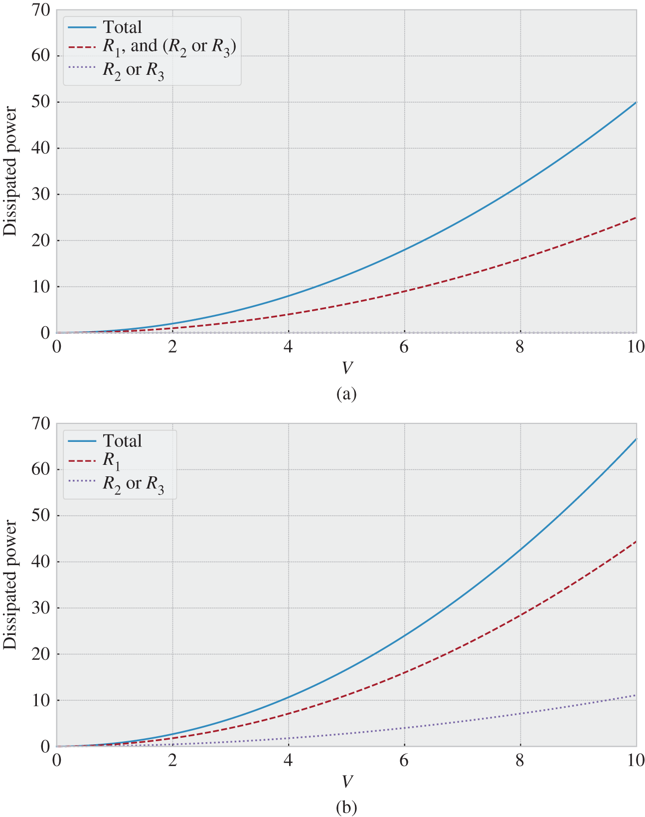
Figure 7.2 Dissipated power measured in watts as a function of the constant voltage  in volts for the circuit presented in Figure 7.1 for
  . (a). Case 2. (b) Case 3.
7.3 Data Layer and Informing Processes
After sensing and measuring processes, the physical layer can be mapped to another, symbolic, domain called data layer. The data layer constitutes a cyber reality where new forms of relations – the logical relations – are established between cyber‐defined elements. Data can be exchanged and processed in different ways by different cyber elements. What is important to remark is that the data layer refers to the symbolic domain and data processes that are level 1 or greater. The focus is on logical relations and meaningful data, not on the measuring, computing, and communication components that are their material support. Therefore, and it is very important to keep this in mind, the data layer is at the last instance about semantics with respect to the cyber elements and their logical relations whose ultimate objective is to produce data that are potentially informative in decision‐making processes at the decision layer.

Figure 7.3 Data layer with four cyber elements: three representing the dissipated power  ,
,  , and
, and  by resistors
  ,
,  , and
, and  from Figure 7.1 and one representing the sum of values obtained from the other three.
Let us illustrate this idea by considering a system whose physical layer is defined in Figure 7.1. Consider that only the dissipated power ![]() ,
, ![]() , and
, and ![]() can be directly observed, with measurements periodically acquired in time with the index
can be directly observed, with measurements periodically acquired in time with the index ![]() . We then have the following data
. We then have the following data ![]() ,
, ![]() , and
, and ![]() , which are level 1 processes related to the
, which are level 1 processes related to the ![]() th time step. We can also process these data and obtain the total power dissipated by the circuit as the sum
th time step. We can also process these data and obtain the total power dissipated by the circuit as the sum ![]() . The topology of the data layer is illustrated in Figure 7.3.
. The topology of the data layer is illustrated in Figure 7.3.
We consider the scenario where each switch is randomly assigned to state a on or off with the same probability of 50% (like tossing a fair coin). Then, the changes in the switch states is faster than the data acquisition, and thus, at each observation time ![]() , the state of the switches is on or off with a probability of 50%. To analyze this problem with probability theory, we will first generalize it by following the approach introduced in Chapter 3.
, the state of the switches is on or off with a probability of 50%. To analyze this problem with probability theory, we will first generalize it by following the approach introduced in Chapter 3.
- System
 : Electric circuit depicted in Figure 7.1.
 - Protocol
 : At each time index
  ,
,  ,
,  , and
, and  is observed and recorded.
 - Attributes
 are the power dissipated by the resistors so that
  (negative power values mean that power is consumed).
 - Experiment
 : Perform
  .
. - The random variable for the
 th observation is:
 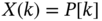 with the sample space
  .
. - The stochastic process is defined as
 , which is memoryless.
To numerically exemplify this situation, we assume that ![]() V, and
V, and ![]() . In this situation, the sample space can be reduced to three outcomes, which are the three cases described in the previous section. Hence, the sample space is
. In this situation, the sample space can be reduced to three outcomes, which are the three cases described in the previous section. Hence, the sample space is ![]() related to case 1, 2, and 3, respectively. If nothing is known about this probability distribution of
related to case 1, 2, and 3, respectively. If nothing is known about this probability distribution of ![]() , we calculate its maximum information entropy as introduced in Chapter 4:
, we calculate its maximum information entropy as introduced in Chapter 4: ![]() bits. However, we know how to map the probabilities of the three events of the sample space by studying the combination of the switch states that result in cases 1, 2, and 3, as follows.
bits. However, we know how to map the probabilities of the three events of the sample space by studying the combination of the switch states that result in cases 1, 2, and 3, as follows.
- Case 1:
 off, or
  on and
  and
and  off, then
  .
. - Case 2:
 on, and only one of
  or
or  off, then
  .
. - Case 3: All on, then
 .
.
Figure 7.4 illustrates a realization of the stochastic process with ![]() .
.
From the probability mass function just determined, we can calculate the entropy of the random variable ![]() as:
as: ![]() bits. In this case,
bits. In this case, ![]() bit is the (mathematical) information contained in the description of the observation protocol and the preliminary knowledge of the physical system itself.
bit is the (mathematical) information contained in the description of the observation protocol and the preliminary knowledge of the physical system itself.
This quantification is strictly related to the question of the value that ![]() will assume considering each observation time is an i.i.d. realization of the random variable
will assume considering each observation time is an i.i.d. realization of the random variable ![]() that is defined by cases 1, 2, and 3. The uncertainty of
that is defined by cases 1, 2, and 3. The uncertainty of ![]() is different from the uncertainty of the particular combination of events (i.e. if the switches are on or off) that resulted in such a value. Considering that
is different from the uncertainty of the particular combination of events (i.e. if the switches are on or off) that resulted in such a value. Considering that ![]() is the only observable attribute in the physical system
is the only observable attribute in the physical system ![]() , there is an unresolvable uncertainty about the state of the system. If
, there is an unresolvable uncertainty about the state of the system. If ![]() W, then we are sure that all switches are on. However, when
W, then we are sure that all switches are on. However, when ![]() W, it is impossible to know without additional data if the physical event that resulted in this outcome is
W, it is impossible to know without additional data if the physical event that resulted in this outcome is ![]() on and
on and ![]() off, or
off, or ![]() off and
off and ![]() on. The analysis of this case will be the focus of Exercise 7.7.
on. The analysis of this case will be the focus of Exercise 7.7.
![Schematic illustration of numerical example of a realization of the stochastic processes P[k] (measured in watts) with the time index k that is the outcome of the experiment Ξ related to the physical system T.](https://imgdetail.ebookreading.net/2023/10/9781119785163/9781119785163__9781119785163__files__images__c07f004.png)
Figure 7.4 Numerical example of a realization of the stochastic processes  (measured in watts) with the time index
  that is the outcome of the experiment
  related to the physical system
  .
.
There are important remarks here. First, the measured data have potential to be informative in a semantic sense and, in this specific case, they can be evaluated using the mathematical information theory. Second, if the only observable attribute is a level 2 process, there might be an increase in the uncertainty related to the actual state of the physical system that led to such an observable outcome. Third, the specific uncertainty to be resolved is a semantic characterization that should be strictly related to the function of the acquired data in the CPS under consideration. Fourth, other aspects could have been added, such as noisy measurements and communication errors that would increase the uncertainty related to the data processes. In summary, the semantic‐functional determination of the acquired and processed data from a given system is what defines what are the possible sources of uncertainty, and thus, which data can be informative to different elements of the CPS.
Another important characterization of the data layer refers to its informing structure, as illustrated in Figure 7.3. Despite the usefulness of the visual and mathematical characterization of networks, we would like to introduce here another form of algebraic formalism to represent the data layer and its constitutive informing processes. The notation is inspired by the algebra of reflexive processes introduced by Vladimir Lefebvre in the late 1960s [10] as part of the cybernetics trend of the Soviet sciences [11]. The conceptualization of a reflexive process is given in the first page of Lefebvre's book Conflicting Structures [10]:
What is a reflexive system? Let us use the following analogy. Imagine a room full of crooked mirrors placed at various angles to each other, as typical in amusement parks. If a pencil falls from a table, it will be reflected by the mirrors in many whimsical ways; then the reflections will be reflected with numerous distortions, ad infinitum. An avalanche of distorted images will flash around the room. A reflexive system is a system of mirrors reflecting each other over and over again. Each mirror is analogous to a person with a particular position relative to the world. The entire complicated stream of mirrors' mutual reflections is an analogue of the reflexive process.
The example with the pencil illustrates the difference between physical processes and social‐psychological ones. A pencil falling is a physical process. If, however, we are interested not only in this fall but in the entire stream of multiple mirror images, we are dealing with a social‐psychological event.
We neither share his philosophical position nor the mathematization proposed in the book. However, the proposed algebraic representation of reflexive systems is a useful tool to characterize informing processes that exist in the data layer of CPSs. The notation is simple, but we need to proceed with care. Consider a physical system ![]() and two elements
and two elements ![]() and
and ![]() . If
. If ![]() and
and ![]() can directly measure or sense
can directly measure or sense ![]() , then the images
, then the images ![]() and
and ![]() are part of the reflexive system;
are part of the reflexive system; ![]() can be read as the image that
can be read as the image that ![]() has of the physical system
has of the physical system ![]() (the capitalization of the fonts is important here). The reflexive system is then
(the capitalization of the fonts is important here). The reflexive system is then ![]() , indicating that the images of the measuring elements are part of the system, regardless of its quality and trustfulness. The element
, indicating that the images of the measuring elements are part of the system, regardless of its quality and trustfulness. The element ![]() is called structure of awareness of the reflexive system. If we consider a slightly different situation where element
is called structure of awareness of the reflexive system. If we consider a slightly different situation where element ![]() also receives data related to the measurement of
also receives data related to the measurement of ![]() , then
, then ![]() is also part of the reflexive system, which is defined by a new structure of awareness
is also part of the reflexive system, which is defined by a new structure of awareness ![]() . Note that in this notation
. Note that in this notation ![]() , and that the sum and multiplication operations are defined in a different way in the proposed formalism; for us, it is not important how to operate with the proposed algebraic formalism, but rather to understand the representation it affords.
, and that the sum and multiplication operations are defined in a different way in the proposed formalism; for us, it is not important how to operate with the proposed algebraic formalism, but rather to understand the representation it affords.
Although the physical system ![]() is the same in both cases, the two reflexive systems are different, and thus, might result in observable differences in their dynamics, as to be discussed later. What is remarkable is that this simple notation can unambiguously differentiate systems that are constituted by physical and symbolic layers. From the structure of awareness, we can directly infer the level of the data processes by counting the number of reflections needed to access the physical system present in the structure of awareness. In this simple example, there is one level 0 process represented by the physical system
is the same in both cases, the two reflexive systems are different, and thus, might result in observable differences in their dynamics, as to be discussed later. What is remarkable is that this simple notation can unambiguously differentiate systems that are constituted by physical and symbolic layers. From the structure of awareness, we can directly infer the level of the data processes by counting the number of reflections needed to access the physical system present in the structure of awareness. In this simple example, there is one level 0 process represented by the physical system ![]() itself, two level 1 processes represented by
itself, two level 1 processes represented by ![]() and
and ![]() , and one level 2 process represented by
, and one level 2 process represented by ![]() . It is important to reinforce that the structure of awareness cannot tell whether the reflection is reliable, but only about its existence as part of the reflexive system. This aspect is important to characterize many times hidden differences in logical relations that constitute CPSs and also to assess potential vulnerabilities introduced by the cyber reality.
. It is important to reinforce that the structure of awareness cannot tell whether the reflection is reliable, but only about its existence as part of the reflexive system. This aspect is important to characterize many times hidden differences in logical relations that constitute CPSs and also to assess potential vulnerabilities introduced by the cyber reality.
Let us now study the physical system ![]() and the data layer depicted in Figure 7.3. The reflexive system can be represented based on the level of the process as follows.
and the data layer depicted in Figure 7.3. The reflexive system can be represented based on the level of the process as follows.
- Level 0: The physical system
 .
. - Level 1: The measurements
 taken by the elements
  ,
,  , and
, and  (respectively related to
  ,
,  , and
, and  ).
). - Level 2: The data process
 carried out by the element
  , whose function is to sum the measurements of
  ,
,  , and
, and  .
. - Reflexive system:
 .
. - Structure of awareness (SAw):
 .
.
It is interesting to see that the numerical example presented in this section refers to the uncertainty related to the ![]() process itself, while Exercise 7.7 will deal with uncertainties of the reflexive system. However, a complete characterization of CPSs also requires explicit characterization of the decision‐making processes and their associated actions, which is the focus of the next section.
process itself, while Exercise 7.7 will deal with uncertainties of the reflexive system. However, a complete characterization of CPSs also requires explicit characterization of the decision‐making processes and their associated actions, which is the focus of the next section.
7.4 Decision Layer and Acting Processes
After being informed, decision‐makers will conduct their respective decision‐making processes, which depend on the structure of awareness of the reflexive system, to define the actions to be taken by agents. The different possibilities of decision‐making processes are presented in Chapter 6. Decisions concern not only direct physical actions (level 0 processes), such as opening a switch, increasing the voltage, or stopping a production line, but also symbolic actions, such as changing of the decision rules or modification of logical links. Nevertheless, as stated in Chapter 6, all the symbolic actions, directly or indirectly, refer to physical actions depending on their specific process level.
The example of the electric circuit from the two previous sections can be used here to illustrate how the structure of awareness enables different decision‐making processes. Hence, the physical layer is the circuit defined in Figure 7.1 and the data layer is the network defined in Figure 7.3 leading to a structure of awareness ![]() . We consider a centralized decision‐making carried out by the element
. We consider a centralized decision‐making carried out by the element ![]() , which is also the agent that can open and close the switches of the circuit, which is the only possible action that is allowed. If the optimization problem is to maximize the dissipated power
, which is also the agent that can open and close the switches of the circuit, which is the only possible action that is allowed. If the optimization problem is to maximize the dissipated power ![]() , the optimal solution considering that the voltage of the source is fixed is to close all the three switches (i.e. the switches of
, the optimal solution considering that the voltage of the source is fixed is to close all the three switches (i.e. the switches of ![]() ,
, ![]() , and
, and ![]() are on, which is case 3). After the optimal solution is found,
are on, which is case 3). After the optimal solution is found, ![]() 's decision is defined and it can then act accordingly. Similar to the structure of awareness, we can propose a structure of action that can be used to represent the agents of the system. In this example, the active system is
's decision is defined and it can then act accordingly. Similar to the structure of awareness, we can propose a structure of action that can be used to represent the agents of the system. In this example, the active system is ![]() and the structure of action
and the structure of action ![]() meaning that
meaning that ![]() is capable of modifying the physical system
is capable of modifying the physical system ![]() .
.
Actually, the case presented in Section 7.3 where the switches are randomly associated with a state on or off has a different structure of action where nodes ![]() ,
, ![]() , and
, and ![]() are both decision‐makers and agents, whose decisions are independent of the state of the system and of each other's decisions. Hence, we have
are both decision‐makers and agents, whose decisions are independent of the state of the system and of each other's decisions. Hence, we have ![]() where the individual decision‐making process is based on rules related to the random assignments of the on and off states for each switch. In this case, node
where the individual decision‐making process is based on rules related to the random assignments of the on and off states for each switch. In this case, node ![]() is neither an agent nor a decision‐maker, only a data processing element.
is neither an agent nor a decision‐maker, only a data processing element.
These two cases are two extreme situations of reflexive–active systems, one purely deterministic with centralized decision‐making and the other purely random decisions by independent decision‐makers. We can also analyze a more intricate scenario where the elements ![]() ,
, ![]() , and
, and ![]() create images of each other to guide their individual decisions. In this case,
create images of each other to guide their individual decisions. In this case, ![]() considering
considering ![]() . If images that the elements
. If images that the elements ![]() ,
, ![]() , and
, and ![]() create of each other states that the individual aim is to maximize the individual dissipated power assuming that they know the possible outcomes of the system and that they cannot communicate their decisions, this problem can be studied through game theory. If Element
create of each other states that the individual aim is to maximize the individual dissipated power assuming that they know the possible outcomes of the system and that they cannot communicate their decisions, this problem can be studied through game theory. If Element ![]() is off, then the payoff is
is off, then the payoff is ![]() regardless of
regardless of ![]() and
and ![]() actions. If Element
actions. If Element ![]() is on, then we have the following payoff table:
is on, then we have the following payoff table:
| Element | |||||
| off | on | ||||
| Element | off | ||||
| on | |||||
It is easy to see that the best response and the pure strategy Nash equilibrium is that all the three elements are on; this is also the global optimum.
Consider a slightly different situation where ![]() and
and ![]() are now dependent by jointly deciding their actions. One can see that by coordinating their on and off actions (whenever one is on, the other is off), they can improve their average payoffs. The coordination will lead to an average individual payoff of
are now dependent by jointly deciding their actions. One can see that by coordinating their on and off actions (whenever one is on, the other is off), they can improve their average payoffs. The coordination will lead to an average individual payoff of ![]() , which is greater than
, which is greater than ![]() . This solution is below the global optimum in terms of total dissipated power and significantly decreases the payoff of
. This solution is below the global optimum in terms of total dissipated power and significantly decreases the payoff of ![]() , but improves the average payoffs of
, but improves the average payoffs of ![]() and
and ![]() and also the fairness of the system. It is worth saying that those two last cases have the same structures of awareness and action, but they are constructed upon different assumptions of how the elements
and also the fairness of the system. It is worth saying that those two last cases have the same structures of awareness and action, but they are constructed upon different assumptions of how the elements ![]() and
and ![]() form the images of each other (the first one based on game‐theoretic assumptions, the second based on explicit cooperation).
form the images of each other (the first one based on game‐theoretic assumptions, the second based on explicit cooperation).
Reflexive–active systems, which have internal structures of awareness and action, allow for self‐development where agents governed by decision‐makers intervene in the physical system based on informative data used in decision‐making processes. The following section will formalize self‐developing reflexive–active systems that are the purified version of CPSs.
7.5 Self‐developing Reflexive–Active System and Cyber‐Physical Systems
The idea of self‐developing reflexive–active environment was introduced as a broader foundational concept of the third‐order cybernetics [12]. As already indicated in Chapter 1, this book has not been written based on the same philosophical background, but the characterization of systems as self‐developing and reflexive–active is appealing and useful for our purposes, and thus, we shall retain it. Our aim here is to formalize it in order to characterize self‐developing reflexive–active systems as a purified version of CPSs.
After the theoretical journey presented in the previous chapters, it is possible to say that the fundamentals of the theory of CPSs are now stated. In the following, we will exemplify how to design a CPS based on the electric circuit studied in the previous sections.
A detailed study of the different dynamics of CPSs will be presented in the next chapter. Despite the simplicity of the proposed example, it clearly shows the potential of the proposed approach to CPSs as self‐developing reflexive–active systems constituted by three layers and cross‐layer processes. In other words, the (observable) behavior of this CPS cannot be reduced by the characterization of, for example, one layer or one process alone. The importance of communications between the cyber elements of the system is also clear. Any communication, in its turn, requires some sort of protocol so transmitters and receivers could actually exchange data [13]. A high‐level vision of communication protocols and other types of protocols needed to design CPSs will be discussed in the following.
7.6 Layer‐Based Protocols and Cyber‐Physical Systems Design
The existence of CPSs presupposes a shared symbolic domain where data are structured and meaningful among relevant elements forming then a common language with syntax and semantics. Therefrom, messages with semantic value can be mapped into physical communication links through which such elements can exchange data. This, of course, indicates that such a common language exists and is materialized through data processes including transmission and reception of meaningful physical signals. The study of languages is the focus of specific disciplines, such as linguistics, semiotics, and logic, which have their own (heated) debates and extremely rich findings. Although those domains should be acknowledged, their extensive study of language as a social phenomenon is well beyond our aims; the reader is referred to [14] as a broad overview of the topic.

Figure 7.5 Self‐developing electric circuit: impact of decision rules and initial conditions. (a)  and
and  with
with  . (b)
. (b)  and
and  with
with  and
and  . (c)
. (c)  , and
, and  with
with 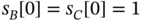 . (d)
. (d)  , and
, and  with
with  and
and  . (e)
. (e)  , and
, and  with
with  . (f)
. (f)  , and
, and  with
with  and
and  .
.
This book mainly focuses on data generated by machines and communication between them. In a nutshell, the processes at the physical layer need to be converted into (analog or digital) signals, which will be the basis of the data to be further processed, exchanged, and used to (directly or indirectly) intervene in the physical layer. Hence, from the data acquisition phase to its use in decision‐making and acting processes, languages specially designed for machines are needed in order to be functional for their specific purposes. Despite the challenges in their design, we factually assume that these languages do exist as part of the enabling ICTs to be presented later in Chapter 9.
This prelude indicates how the physical layer is apprehended and symbolically manipulated through machine‐type languages to enable the deployment of CPSs. However, one important missing aspect refers to the way the different elements of the CPS coordinate their actions, and for this, we need protocols. This term has been particularly employed in the computer networking literature with the following definition [15]:
[A] protocol defines the format and the order of messages exchanged between two or more communicating entities, as well as the actions taken on the transmission and/or receipt of a message or other event.
We will employ a similar but more general definition as stated next.
Thus, the protocols are designed to guarantee the conditions of reproduction of the CPS in the sense defined in Chapter 2. Each particular CPS requires specific protocols that are codetermined by the intricate intra‐ and cross‐layer interactions. At the same time, the same protocols also codetermine how those interactions are coordinated. A proper conceptualization of any CPS then necessarily requires the determination of its protocols and how they affect, and are affected by, its behavior. Some key aspects of layer‐based protocols and how they impact on the design of CPS are summarized below.
- Observation protocol for measuring and sensing cross‐layer processes that determine the data acquisition from the physical layer to the data layer. The main factors to be taken into account are: (i) when a new measurement is taken (e.g. periodic sampling, aperiodic event‐triggered acquisition, or hybrid between both), and (ii) how the sample is processed to be recorded (e.g. the instantaneous measured value, or the mean value between the two recording times, time‐indexed or not, analogue or digital, and how data are coded to be interpretable).
- Protocols for data processes that are employed to produce potentially informative data used by decision‐makers. The main factors are: (i) what data are to be used and how to aggregate and fuse them (e.g. based on spatial proximity of sensors, time indices, or statistical relations), (ii) how to solve problems of heterogeneity of sources that may use different codes to record their data (i.e. their interoperability), and (iii) how to preserve secrecy or privacy of data to be shared (e.g. sharing only part of the data, cryptography, or manipulation of metadata).
- Communication protocols that are used to guarantee that the cyber elements can exchange data that will materially enable the structure of awareness of the CPS. This is related to different aspects of communication systems like (i) how to access the physical medium (e.g. wireless or wired), (ii) how to guarantee that the message was successfully received, and (iii) how to send messages over a network. Actually, modern communication networks are also CPSs and can be studied accordingly.
- Decision‐making protocols are related to how decisions are made, being them centralized, decentralized, or distributed as discussed in more detail in Chapter 6. The protocol indicates, for instance, when decisions are taken, the order of the decisions in systems with more than one decision‐maker, how distributed decision are taken (e.g. majority vote, consensus, logical gates), and the hierarchy of decision‐makers (e.g. if there are decision‐makers with greater autonomy than others in decentralized systems).
- Action protocols define how and when agents intervene in the CPS. After the information about the decision‐making process is available, the protocol defines how to coordinate and organize the agents operating in the CPS to avoid, for example, undesirable collective effects.
More details can be found in the rich literature of different fields such as communication and computing networks, control theory, signal processing, data fusion, and computer sciences [13, 15–17].
Let us return to Example 7.2 in order to illustrate the layer‐based protocols and their impact on the CPS behavior.
Examples 7.2 and 7.3, as well as Section 7.3, indicate that the same CPS may have different behaviors depending not only on the decision rules but also on its initial conditions and protocols. Roughly speaking, one may observe stable, oscillatory, or random dynamics; a theoretically grounded classification will be introduced in the next chapter that focuses on the dynamics of CPSs. It is noteworthy that the proper characterization of the CPS must consider its three layers and cross‐layer processes even in the pedagogical examples presented here.
7.7 Summary
This chapter finally introduced the core concept of this book, namely the three layers of CPSs. We indicated how to characterize the physical, data, and decision layers, as well as cross‐layer processes. A few idealized examples were provided to illustrate (i) the way the concepts presented in the previous chapters can be employed to characterize CPSs, and (ii) the need for the proposed approach to fully apprehend the system dynamics. In the following chapters, we will build upon this proposed theory to investigate the dynamics of CPSs but still in idealized scenarios (Chapter 8), its main enabling technologies in 2020 (Chapter 9), critical evaluation of existing CPSs (Chapter 10), and considerations beyond technology (Chapter 11). The preliminary studies that resulted in this chapter are reported in the following papers [4–7]. Another approach to CPSs is presented in [16], which is a highly recommended book for advanced readers who are more interested in computer sciences, control theory, and robotics. Although its approach differs from the one taken in this book, the contents surely supplement each other.
Exercises
- 7.1 Information of events Consider the numerical example presented in Section 7.3. The task is to characterize the uncertainty of events that generate the outcome observable
 .
.
- Define a random variable
 that characterizes the events of interest, i.e. the combination of the switches that are on and off.
 - Compute the conditional probabilities
 and the conditional entropy
  .
. - Compute the mutual information between
 and
and  . What does it mean?
 - Prove that
 . What is the fundamental assumption that results in this equality?
- Define a random variable
- 7.2 Charging electric vehicles Consider a charging station for electric vehicles (EVs). There are three plugs but only one can be in use while the other two are off because of the capacity limitations of the cables. The task is to design a CPS deployment to coordinate the resource allocation of plugs.
- Propose a solution using a centralized decision‐making that includes the SAw, SAc, and layer‐based protocols.
- Propose a solution using a decentralized decision‐making that includes the SAw, SAc, and layer‐based protocols.
- Propose a solution using a distributed decision‐making that includes the SAw, SAc, and layer‐based protocols.
- Compare these three approaches by indicating their benefits and drawbacks.
References
- 1 Jasperneite J, Sauter T, Wollschlaeger M. Why we need automation models: handling complexity in industry 4.0 and the internet of things. IEEE Industrial Electronics Magazine. 2020;14(1):29–40.
- 2 Karnouskos S, Leitao P, Ribeiro L, Colombo AW. Industrial agents as a key enabler for realizing industrial cyber‐physical systems: multiagent systems entering industry 4.0. IEEE Industrial Electronics Magazine. 2020;14(3):18–32.
- 3 Uslar M, Rohjans S, Neureiter C, Pröstl Andrén F, Velasquez J, Steinbrink C, et al. Applying the smart grid architecture model for designing and validating system‐of‐systems in the power and energy domain: a European perspective. Energies. 2019;12(2):258.
- 4 Kühnlenz F, Nardelli PHJ. Dynamics of complex systems built as coupled physical, communication and decision layers. PLoS One. 2016;11(1):e0145135.
- 5 Kühnlenz F, Nardelli PHJ, Alves H. Demand control management in microgrids: the impact of different policies and communication network topologies. IEEE Systems Journal. 2018;12(4):3577–3584.
- 6 Nardelli PHJ, Kühnlenz F. Why smart appliances may result in a stupid grid: examining the layers of the sociotechnical systems. IEEE Systems, Man, and Cybernetics Magazine. 2018;4(4):21–27.
- 7 Gutierrez‐Rojas D, Ullah M, Christou IT, Almeida G, Nardelli PHJ, Carrillo D, et al. Three‐layer approach to detect anomalies in industrial environments based on machine learning. In: 2020 IEEE Conference on Industrial Cyberphysical Systems (ICPS). vol. 1. IEEE; 2020. p. 250–256.
- 8 Cacciapuoti AS, Caleffi M, Tafuri F, Cataliotti FS, Gherardini S, Bianchi G. Quantum internet: networking challenges in distributed quantum computing. IEEE Network. 2019;34(1):137–143.
- 9 Adonias GL, Yastrebova A, Barros MT, Koucheryavy Y, Cleary F, Balasubramaniam S. Utilizing neurons for digital logic circuits: a molecular communications analysis. IEEE Transactions on Nanobioscience. 2020;19(2):224–236.
- 10 Lefebvre V. Conflicting Structures. Leaf & Oaks Publishers; 2015.
- 11 Gerovitch S. From Newspeak to Cyberspeak: A History of Soviet Cybernetics. MIT Press; 2004.
- 12 Lepskiy V. Evolution of cybernetics: philosophical and methodological analysis. Kybernetes. 2018;47(2):249–261.
- 13 Popovski P. Wireless Connectivity: An Intuitive and Fundamental Guide. John Wiley & Sons; 2020.
- 14 Hamawand Z. Modern Schools of Linguistic Thought: A Crash Course. Springer Nature; 2020.
- 15 Kurose JF, Ross KW. Computer Networking: A Top‐Down Approach. Pearson Education, Inc.; 2017.
- 16 Alur R. Principles of Cyber‐Physical Systems. MIT Press; 2015.
- 17 Lahat D, Adali T, Jutten C. Multimodal data fusion: an overview of methods, challenges, and prospects. Proceedings of the IEEE. 2015;103(9):1449–1477.