
CHAPTER 5
PROGRAMMING THE DB-BOT
In the previous chapter, you built DB-Bot, a programmable robot that has a sensor to measure distance, two wheels to move freely in the environment, an LED, and a micro-controller to run its control programs. In this chapter, you will program the DB-Bot.
A software program determines the behavior of the robot, specifying what actions the robot will take given the information received by its sensors. A carefully designed and tested program allows the robot to take reasonable actions in its environment such that a human being observing the robot would agree that the robot is behaving intelligently. The software programs that you will write demonstrate intelligent behavior by doing the following:
![]() Sensing the environment
Sensing the environment
![]() Selecting actions based on the sensed data
Selecting actions based on the sensed data
![]() Performing the selected actions in the environment
Performing the selected actions in the environment
The PICAXE micro-controller provides programming environments for developing software programs in the BASIC programming language on a personal computer (PC). You will learn how to write programs and download them into the PICAXE micro-controller. When the micro-controller runs your programs on the robot, observe the robot’s behavior. If the robot does not do exactly what you intended, you can debug and change the program until the robot demonstrates the intended behavior. As you will see, changing the behavior of a robot by changing the steps in its control software offers a lot of flexibility in robot development.
Before implementing an intelligent behavior on the DB-Bot, you will look at three simple standalone software programs that demonstrate the following:
![]() How to turn on/off an LED
How to turn on/off an LED
![]() How to read the distance values from the distance sensor
How to read the distance values from the distance sensor
![]() How to control the speed and direction of the rotation of the RC servos
How to control the speed and direction of the rotation of the RC servos
Next, you will see how to combine these standalone programs to make the DB-Bot move around in its environment while avoiding obstacles, which is a demonstration of an intelligent behavior.
You do not need prior programming knowledge to achieve this. Each programming example is explained in detail. If you wish, you can start writing new programs by cutting and pasting sections of the code from these examples. Later, you can expand your programming knowledge by using your imagination and integrating what you will find interesting in the PICAXE micro-controller documentation into your programs.
A PROGRAMMER’S VIEW OF THE MICRO-CONTROLLER
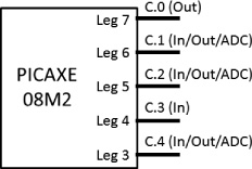
Figure 5.1 shows the schematic view of the PICAXE-08M2 micro-controller from a programming perspective. The schematic shows only the pins that can be controlled by the programs and ignores other pins such as voltage supply and download pins. As you can see, the PICAXE-08M2 micro-controller has five programmable pins, labeled “C.0” to “C.4.” Note that the programmable pin numbers are not the same as the physical leg numbers. For example, pin C.0 is leg 7 of the micro-controller chip.
Figure 5.1
The schematics of PICAXE-08M2 micro-controller programmable pins.
© 2014 Behnam Salemi, All Rights Reserved.
Each programmable pin of the micro-controller can have the following functions:
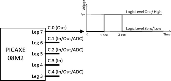
![]() Digital output (out): An output pin is a pin by which a micro-controller sends signals, data, or commands to the outside world. As an analogy, the mouth of a human is an output by which the human sends vocal signals, data, or commands to the outside world. A digital output pin is an output pin that can output only one of two possible values at a time. These are called “high/low,” “logic level one/logic level zero,” or “1/0.” On a micro-controller, a digital output pin can output two voltage levels. One is close to the V+ of the power supply, which is called “high,” “logic level one,” or “1,” and the other is close to the ground voltage of the power supply, which is called “low,” “logic level zero,” or “0.” Figure 5.2 shows the output pin C.0 sending out a digital pulse signal. Initially, C.0 outputs ground level voltage, 0 volt (logic level zero/low). After one second, the pin voltage jumps to the power supply voltage, V+ volt (logic level one/high) and remains there for one second. Then, the C.0 voltage drops back to ground level voltage, 0 volt (logic level zero/low) and remains there.
Digital output (out): An output pin is a pin by which a micro-controller sends signals, data, or commands to the outside world. As an analogy, the mouth of a human is an output by which the human sends vocal signals, data, or commands to the outside world. A digital output pin is an output pin that can output only one of two possible values at a time. These are called “high/low,” “logic level one/logic level zero,” or “1/0.” On a micro-controller, a digital output pin can output two voltage levels. One is close to the V+ of the power supply, which is called “high,” “logic level one,” or “1,” and the other is close to the ground voltage of the power supply, which is called “low,” “logic level zero,” or “0.” Figure 5.2 shows the output pin C.0 sending out a digital pulse signal. Initially, C.0 outputs ground level voltage, 0 volt (logic level zero/low). After one second, the pin voltage jumps to the power supply voltage, V+ volt (logic level one/high) and remains there for one second. Then, the C.0 voltage drops back to ground level voltage, 0 volt (logic level zero/low) and remains there.
Figure 5.2
The output pin C.0 sending out a digital pulse signal.
© 2014 Behnam Salemi, All Rights Reserved.
![]() Digital input (in): An input pin is a pin by which a micro-controller receives signals, data, or commands from the outside world. As an analogy, the eyes and ears of a human are inputs by which that human receives visual and vocal signals, data, or commands from the outside world. A digital input pin is an input pin that can receive only one of two possible values at a time. They are called “high/low,” “logic level one/logic level zero,” or “1/0.” On a micro-controller, a digital input pin can accept two voltage levels. One is close to the V+ of the power supply, which is called “high,” “logic level one,” or “1,” and the other is close to the ground voltage of the power supply, which is called “low,” “logic level zero,” or “0”. Figure 5.3 shows the input pin C.3 receiving a digital step signal. Initially, C.3 receives ground level voltage, 0 volt (logic level zero/low). After one second, the voltage that enters the input pin jumps to the power supply voltage, V+ volt (logic level one/high) and remains there.
Digital input (in): An input pin is a pin by which a micro-controller receives signals, data, or commands from the outside world. As an analogy, the eyes and ears of a human are inputs by which that human receives visual and vocal signals, data, or commands from the outside world. A digital input pin is an input pin that can receive only one of two possible values at a time. They are called “high/low,” “logic level one/logic level zero,” or “1/0.” On a micro-controller, a digital input pin can accept two voltage levels. One is close to the V+ of the power supply, which is called “high,” “logic level one,” or “1,” and the other is close to the ground voltage of the power supply, which is called “low,” “logic level zero,” or “0”. Figure 5.3 shows the input pin C.3 receiving a digital step signal. Initially, C.3 receives ground level voltage, 0 volt (logic level zero/low). After one second, the voltage that enters the input pin jumps to the power supply voltage, V+ volt (logic level one/high) and remains there.
Figure 5.3
The input pin C.3 receiving a digital step signal.

© 2014 Behnam Salemi, All Rights Reserved.
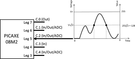
![]() Analog input or analog to digital converter (ADC): An analog input pin is an input pin that can receive a wide range of values from the outside world. The range could be, for example, any voltage between ground and the power supply voltage. Because today’s micro-controllers are digital devices, they cannot directly detect or store analog signals in their analog form. Therefore, they must use a device that converts analog signals to digital values and then store them. The device that converts an analog signal to digital is called an analog to digital converter (ADC). The PICAXE-08M2 micro-controller has three built-in ADC devices on its C.1, C.2, and C.4 pins. Figure 5.4 shows ADC input pin C.2 receiving an analog input wave that changes over time. The vertical axis on the left shows the range of the voltages that enter the ADC pin, which is between 0 and V+. The vertical axis on the right shows the numeric values that the ADC assigns to those voltages. As you see, the ADC assigns the numeric value 255 to a signal that has V+ volt and assigns the numeric value 0 to a signal that has 0 volt. The ADC also proportionally assigns values between 0 and 255 to signals between 0 and V+ volts. For example, it will assign half of 255, which is approximately 128, to the two points on the analog wave at half of V+, (V+/2), volts. After a signal voltage level is converted into numeric values, the micro-controller can easily read them from the ADC device and use them in its decision-making.
Analog input or analog to digital converter (ADC): An analog input pin is an input pin that can receive a wide range of values from the outside world. The range could be, for example, any voltage between ground and the power supply voltage. Because today’s micro-controllers are digital devices, they cannot directly detect or store analog signals in their analog form. Therefore, they must use a device that converts analog signals to digital values and then store them. The device that converts an analog signal to digital is called an analog to digital converter (ADC). The PICAXE-08M2 micro-controller has three built-in ADC devices on its C.1, C.2, and C.4 pins. Figure 5.4 shows ADC input pin C.2 receiving an analog input wave that changes over time. The vertical axis on the left shows the range of the voltages that enter the ADC pin, which is between 0 and V+. The vertical axis on the right shows the numeric values that the ADC assigns to those voltages. As you see, the ADC assigns the numeric value 255 to a signal that has V+ volt and assigns the numeric value 0 to a signal that has 0 volt. The ADC also proportionally assigns values between 0 and 255 to signals between 0 and V+ volts. For example, it will assign half of 255, which is approximately 128, to the two points on the analog wave at half of V+, (V+/2), volts. After a signal voltage level is converted into numeric values, the micro-controller can easily read them from the ADC device and use them in its decision-making.
Figure 5.4
The ADC input pin C.2 receiving an analog input wave.
© 2014 Behnam Salemi, All Rights Reserved.
Some of the PICAXE-08M2 micro-controller pins can perform all the aforementioned functions. However, a pin needs to be configured to perform any one of these functions and can perform only one of them at time. A micro-controller’s pins may perform other functions as well. For example, a pin can be a digital-to-analog converter (DAC). This will be an output that functions the opposite of an ADC. A DAC can generate analog output on a pin when the micro-controller writes numeric values into the DAC device. A complete list of the functions that the PICAXE-08M2 micro-controller pins can support is given in the PICAXE micro-controller document picaxe_manual1. (Search the document for “pinout diagrams.”)
SETTING UP THE PROGRAMMING ENVIRONMENT
The PICAXE micro-controller provides two programming environments for writing programs in the BASIC programming language:
![]() AXEpad. AXEpad is available for Mac, Windows, and Linux.
AXEpad. AXEpad is available for Mac, Windows, and Linux.
![]() PICAXE Programming Editor. This environment is for Windows only.
PICAXE Programming Editor. This environment is for Windows only.
Using these environments, you can write, debug, and download your programs into the PICAXE micro-controller. You can download AXEpad and PICAXE Programming Editor from www.picaxe.com/software. For this book’s projects, you will use AXEpad, as it can run on Mac, Windows, and Linux platforms. However, the PICAXE website recommends using PICAXE Programming Editor if you are using the Windows platform.
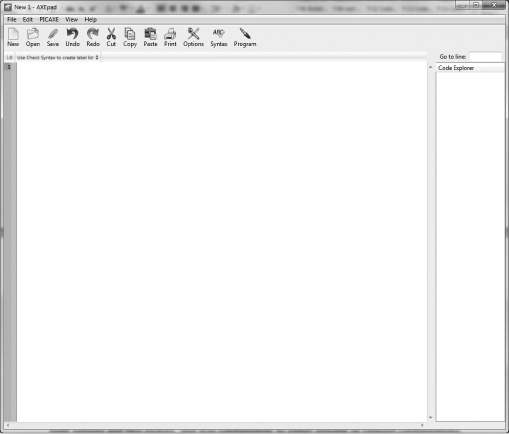
Download AXEpad from www.picaxe.com/software and follow the instructions to install it. Figure 5.5 shows AXEpad’s opening screen.
Figure 5.5
The AXEpad programming environment.
© 2014 Behnam Salemi, All Rights Reserved.
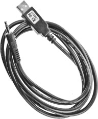
You will use the PICAXE USB download cable, shown in Figure 5.6, to download your programs into the PICAXE memory. To use this cable, you must install its driver. Download AXE027_USB_Driver from www.picaxe.com/software and follow the instructions to install it. There is more detailed information on the AXE027_USB_Driver product page for your reference in case you encounter any problem during installation.
Figure 5.6
The PICAXE USB download cable.
© 2014 Behnam Salemi, All Rights Reserved.
After you install the driver, follow these steps to configure AXEpad:
1. Connect the PICAXE USB download cable to a USB port on your computer.
2. Start AXEpad.
3. Click the Options button on the AXEpad toolbar.
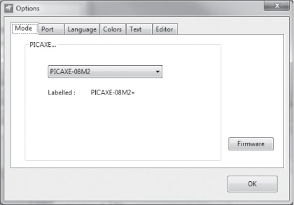
4. Under the Mode tab, select PICAXE-08M2, as shown in Figure 5.7. This is the type of PICAXE micro-controller being used.
Figure 5.7
Select PICAXE-08M2 in the Mode tab.
© 2014 Behnam Salemi, All Rights Reserved.
5. Find out what COM port your operating system has assigned to the PICAXE USB download cable. To get this information in Windows, open the Device Manager (available from the Control Panel), click the Ports tab, and look for the AXE027 PICAXE USB entry. The assigned COM port is specified at the end of the entry. For Mac and Linux operating systems, consult your OS manual for details.
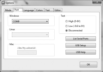
6. Click the Port tab and select the COM port assigned to the PICAXE USB download cable, as shown in Figure 5.8. Then click OK.
Figure 5.8
Setting up the programming environment.
© 2014 Behnam Salemi, All Rights Reserved.
CONTROLLING THE LED
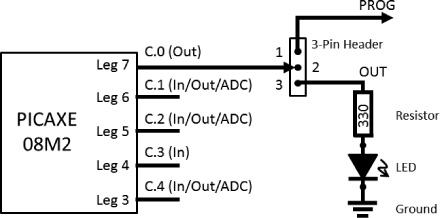
The first program that you will look at shows how to turn on the DB-Bot LED. The schematics in Figure 5.9 show how the LED is connected to the PICAXE micro-controller: through the three-pin header to pin C.0. This is necessary because the output pin C.0 is shared between the LED and the pin that is required for programming the micro-controller. When pin header 2 (C.0) is connected to pin 3 (OUT) of the three-pin header, pin C.0 is connected to the LED. When pin header 2 (C.0) is connected to pin 1 (PROG) of the three-pin header, pin C.0 is used for programming the micro-controller.
Figure 5.9
The LED connection to the micro-controller.
© 2014 Behnam Salemi, All Rights Reserved.
When the LED is connected to pin C.0, a logic level one/high on output pin C.0 causes a positive voltage to go through the 330 ohm resistor, through the LED, and to the ground, which turns on the LED. Similarly, a logic level zero/low causes pin C.0 to output a ground level voltage, resulting in both ends of the LED being connected to the ground; this turns off the LED. If there is a program that can set the state of C.0 to high, the LED will turn on; if it can set the state of C.0 to low, it will turn the LED off.
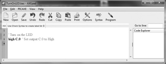
Figure 5.10 shows a program that turns on the LED by setting C.0 to High. Line 1 of the program is a comment, which contains information for the programmer about the program and is ignored by the computer. Comments start with an apostrophe (')ora semicolon (;) and continue to the end of the line. The comment of line 1 explains that this program turns on the LED.
Figure 5.10
A program that turns on the LED.
© 2014 Behnam Salemi, All Rights Reserved.
On line 2, high C.0 is a BASIC programming language command, which, when executed by the PICAXE micro-controller, sets the C.0 output pin to High. high is the command and C.0 is the parameter of the high command. It can be set to other output pins to set them to High. For example, the command high C.1 will set the output pin C.1 to High.
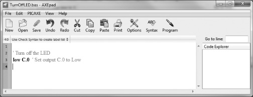
Figure 5.11 is a similar program that turns off the LED. Line 1 of this program is a comment. Line 2 consists of another BASIC command, low C.0. It sets the output pin C.0 to Low, which turns off the LED.
Figure 5.11
A program that turns off the LED.
© 2014 Behnam Salemi, All Rights Reserved.
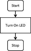
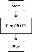
Figure 5.12 and Figure 5.13 contain flowcharts of these programs, respectively. The flowcharts consist of a start step, the action step (Turn On LED or Turn Off LED), and the stop step. The start state for each program is on line 1 and the action step is on line 2. The stop step is optional in these programs, as there are no other actions that will be performed after line 2. However, you can add the BASIC programming language stop command on line 3 of the both programs to explicitly stop the program.
Figure 5.12
A flowchart for the program that turns on the LED.
© 2014 Behnam Salemi, All Rights Reserved.
Figure 5.13
A flowchart for the program that turns off the LED.
© 2014 Behnam Salemi, All Rights Reserved.
Copy each of the programs shown in Figure 5.10 and Figure 5.11 in AXEpad and save them separately in two files called TurnOnLED.bas and TrunOffLED.bas, respectively. You can also download them from this book’s companion website. (To access this website, visit www.cengageptr.com/downloads and search for the title of this book.) At this stage, you’ve saved these two programs on your Mac or PC computer. Before they can be run on the micro-controller, however, they need to be transferred, or downloaded, into the micro-controller’s memory. To download the programs, follow these steps:
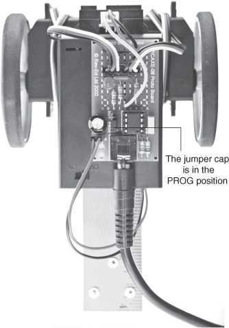
1. Turn the robot off and connect the PICAXE USB download cable to DB-Bot. Use the jumper cap that was included in the PICAXE 8-Pin Proto Kit to set the three-pin header to the PROG position by connecting the jumper cap to the center and the PROG pin headers, as shown in Figure 5.14.
Figure 5.14
Connect the PICAXE USB download cable to DB-Bot and set the three-pin header to the PROG position.
© 2014 Behnam Salemi, All Rights Reserved.
2. Open the TurnOnLED.bas file in AXEpad (if it is not already open).
3. Click the Program button on the AXEpad toolbar and immediately turn on the DB-Bot. A window similar to the one shown in Figure 5.15 will open and the download will begin.
Figure 5.15
This window will open when you download the program.

© 2014 Behnam Salemi, All Rights Reserved.
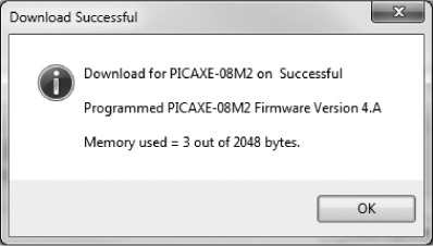
4. When the download is complete, you will see the Download Successful window, shown in Figure 5.16. Click OK.
Figure 5.16
The Download Successful window.
© 2014 Behnam Salemi, All Rights Reserved.
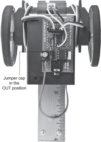
5. Disconnect the PICAXE USB download cable and move the three-pin header to the OUT position by connecting the jumper cap to the center and the OUT pin headers, as shown in Figure 5.17. You should see the LED turn on! (Note that sometimes you need to power cycle the robot to see the downloaded program running.)
Figure 5.17
Move the jumper cap to the OUT position.
© 2014 Behnam Salemi, All Rights Reserved.
6. Repeat steps 1–5 to download the TurnOffLED.bas program and turn off the LED.
READING DISTANCE SENSOR VALUES
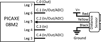
Figure 5.18 shows how the distance sensor is connected to the micro-controller. The sensor has three wires. The red and black wires are connected to the V+ and grounds, respectively, while the yellow wire is connected to pin C.2 of the micro-controller. Pin C.2 is an ADC input and converts the analog values of the distance sensor to a digital number between 0 and 255. The yellow wire generates an analog voltage that is between ground and V+ and is proportional to the distance of the sensor from an object in front. The closer the object, the higher the voltage; the voltage drops to the ground level if the object is farther than a certain distance. The distance range of the sensor selected for this project is 10–80 cm.
Figure 5.18
The distance sensor connection to the micro-controller.
© 2014 Behnam Salemi, All Rights Reserved.
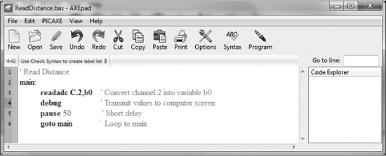
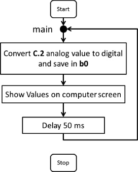
The ReadDistance.bas program shown in Figure 5.19 consists of a loop that continuously reads the analog values of pin C.2, converts them to digital values, and saves them in a variable called b0. Line 1 is a comment that describes what the program does. The main: on line 2 is a label that marks a point in the program that can be addressed later. The readadc C.2,b0 command on line 3 configures pin C.2 as an ADC input, converts the analog value of pin C.2 to a digital number and saves the number in variable b0. The debug command on line 4 sends the values of all micro-controller variables to the computer screen for verification. The pause 50 command on line 5 generates a 50 ms delay, and the goto main command on line 6 jumps to the label main on line 2, causing the commands on lines 3, 4, 5, and 6 to be executed again. As you can see, the combination of the main label on line 2 and the goto main command on line 6 creates a loop. Because this loop never ends, it is called an “infinite loop.” Figure 5.20 shows a flowchart of this program.
Figure 5.19
The ReadDistance.bas program.
© 2014 Behnam Salemi, All Rights Reserved.
Figure 5.20
A flowchart for the ReadDistance.bas program.
© 2014 Behnam Salemi, All Rights Reserved.
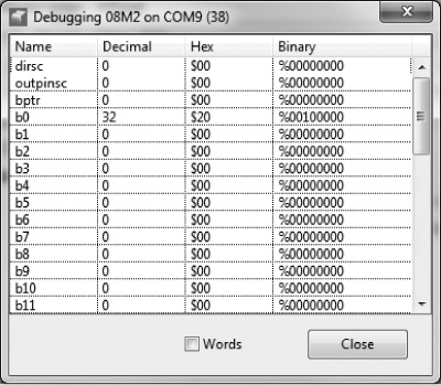
Copy this program in AXEpad and save it in a file called ReadDistance.bas or download a copy of the file from the companion website. Then download it to the micro-controller. For this program, you need to keep the three-pin header in the PROG position because the debug command uses pin C.0 to send values to your computer. Figure 5.21 shows how the debug command window looks. As you can see, the window looks like a table, and in this table the value of b0 is 32 Decimal. While the program is running, move your hand in front of the distance sensor. Observe how the value of variable b0 changes in the table as your hand moves closer to or farther from the sensor. You will notice that the value of variable b0 gets larger when your hand is closer to the sensor and gets smaller when your hand moves away. This shows that larger values of variable b0 are the indication of closer objects to the distance sensor.
Figure 5.21
Reading the values of the distance sensor.
© 2014 Behnam Salemi, All Rights Reserved.
PROGRAMMING THE RC SERVOS
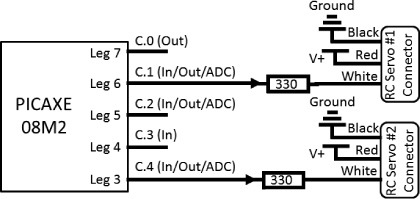
Figure 5.22 shows how the RC servos are connected to the micro-controller. Each RC servo has three wires. The red and black wires are connected to the V+ and grounds, respectively, and the white wire is an input control line to receive the signal required to move the servo to different locations at different speeds. The RC servo 1 control line is connected to the output pin C.1 through a 330 ohm resistor, and the RC servo 2 control line is connected to the output pin C.4 through a 330 ohm resistor.
Figure 5.22
The RC servos’ connections to the micro-controller.
© 2014 Behnam Salemi, All Rights Reserved.
The PICAXE micro-controller offers specific commands for driving RC servos. The BASIC programming language’s servo command initializes the position of the RC servos. The range of available positions in the servo command is 75–225, with 150 being at the center point. After you initialize the RC servos using the servo command, you use the servopos command to change the position of the servos during the course of the program.
The RC servos used in this project have continuous rotation, and for this type of servo the servo position is actually the speed of the rotation of the servo. Initializing the RC servos to stop at the center point (150) will allow the servos to have equal range for turning both directions. The farther the position value is from the center position of 150 in each direction, the faster the servo will turn in that direction.
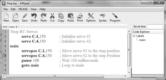
Figure 5.23 shows the Stop.bas program, which initializes the RC servos to stop at the desired position of 150. On line 2, the first parameter of the servo C.1, 150 command, C.1, sets pin C.1 as a digital output. The second parameter of the servo C.1, 150 command, 150, specifies the initial position to which the servo 1 should move. Similarly, line 3 assigns pin C.4 to servo 2 and initializes its position to 150.
Figure 5.23
The Stop.bas program.
© 2014 Behnam Salemi, All Rights Reserved.
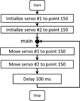
The servopos C.1, 150 command on line 5 and servopos C.4, 150 command on line 6 keep servo 1 and servo 2 at the stop position 150 in the loop formed by the main label on line 4 and the goto main command on line 8. Line 7 adds a 100 ms delay in the loop. Figure 5.24 shows a flowchart of this program.
Figure 5.24
A flowchart of the Stop.bas program.
© 2014 Behnam Salemi, All Rights Reserved.
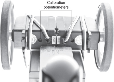
Download this program into the micro-controller and run it. Most likely, you will notice that the servos are not stopped and are turning in some direction. In this case, it is necessary to calibrate the RC servos to stop at the desired position. To calibrate the RC servos, follow these steps:
1. Find the calibration potentiometer on the side of each RC servo (see Figure 5.25).
Figure 5.25
The calibration potentiometers.
© 2014 Behnam Salemi, All Rights Reserved.
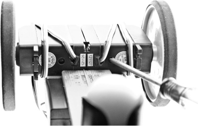
2. Using a small screwdriver, slowly tune each servo’s potentiometer (see Figure 5.26) until the servo stops turning. This completes the calibration process.
Figure 5.26
Calibrating the RC servos’ stop positions.
© 2014 Behnam Salemi, All Rights Reserved.
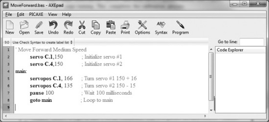
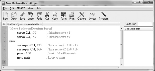
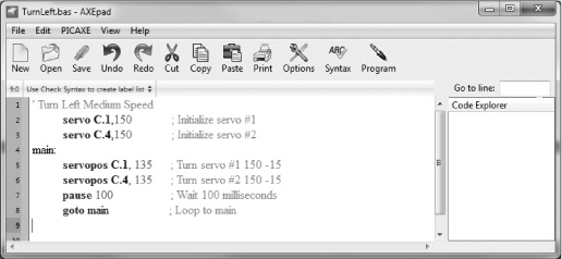
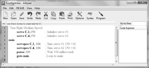
Figure 5.27 shows the MoveForward.bas program, which moves the DB-Bot forward at a medium speed. This program is very similar to the Stop.bas program. The only difference is that the position values on lines 5 and 6 are changed such that RC servos 1 and 2 turn in directions that move the robot forward. Similarly, Figure 5.28, Figure 5.29, and Figure 5.30 show the MoveBackward.bas, TurnLeft.bas, and TurnRight.bas programs. These move the DB-Bot backward, left, and right, respectively.
Figure 5.27
The MoveForward.bas program.
© 2014 Behnam Salemi, All Rights Reserved.
Figure 5.28
The MoveBackward.bas program.
© 2014 Behnam Salemi, All Rights Reserved.
Figure 5.29
The TurnLeft.bas program.
© 2014 Behnam Salemi, All Rights Reserved.
Figure 5.30
The TurnRight.bas program.
© 2014 Behnam Salemi, All Rights Reserved.
You might have noticed that in MoveForward.bas, the servos assigned position values are not equally distanced from the center point, 150. Specifically, the servo 1 position value is 166, which is 16 steps above the stop point (150), but the servo 2 position value is 135, which is 15 steps below the stop point. Theoretically, both servos position values should have been the same distance (either 15 or 16 steps) from the center point (150) to have both servos turn at the same speed in different directions, moving the robot forward on a straight path. In practice, however, the servos are not identical and might turn at slightly different speeds given the same position values. In addition, the wheels’ diameters might not be exactly the same, and the robot might not have been assembled in perfect symmetry. Therefore, assigning position values equally distanced from the center point to the servos might cause the DB-Bot to veer left or right. To fix this problem, fine-tuning is necessary. You can start by assigning equal distance position values to the servos and experiment with DB-Bot to see if it moves on a straight path. If not, modify each servo’s position value until the robot moves in a straight line.
GOING FOR A STROLL
Among the programs that have been developed so far, ReadDistance.bas gives DB-Bot the ability to “sense” an aspect of its environment—namely its distance from other objects—and MoveForward.bas and TurnRight.bas give DB-Bot the ability to “act” in its environment. Now you will learn about Stroll.bas, which adds the third ability of “action selection based on the sensed data” to DB-Bot. Stroll.bas combines the ReadDistance.bas, MoveForward.bas, and TurnRight.bas programs to give DB-Bot the ability to stroll in the environment while avoiding obstacles, which is an example of an intelligent behavior.
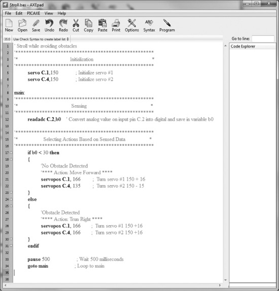
The Stroll.bas program is shown in Figure 5.31. Lines 5 and 6 initialize the RC servos. The main label on line 8 is the beginning of the program’s main loop. Line 12 is the sensing section of the program, which reads the distance value from the distance sensor and saves it in the b0 variable.
Figure 5.31
The Stroll.bas program.
© 2014 Behnam Salemi, All Rights Reserved.
Line 17 is a new section. It is where the action selection is done. The if b0 < 30 then command on this line checks to see if the value of b0 is less than 30. If so, the program proceeds to execute the commands under the then command, which are enclosed by an open curly bracket ({)online18and aclosedcurly bracket (}) on line 23. As you can see, executing the commands enclosed by these brackets moves the robot forward. However, if the value of b0 is not less than 30 (that is, it is either equal or larger), the program will proceed to execute the commands under the else command, which are enclosed by an open curly bracket on line 25 and a closed curly bracket on line 30. As you can see, executing the commands enclosed by these brackets turns the robot to the right.
The check on line 17 is designed based on how the distance sensor used in this project works. The values of the distance sensor read into the b0 variable that are less than 30 mean there is enough empty space in front of the robot to move forward. In this situation, the if b0 < 30 then command returns TRUE and the robot moves forward. However, if the values of the distance sensor are equal or above 30, it means there is an obstacle close to the robot. In this situation, the if b0 < 30 then command would return FALSE and the robot would start turning right.
After executing either the move forward action or the turn action (depending on the result of the check on line 17), the program proceeds to the endif command on line 31 and, after a 500 ms delay, goes to line 8 and loops. In the next loop of the program, the sensor is read again and the check is performed again. If the value is still greater than or equal to 30, the “turn” command will be selected again and will continue to execute. As long as the b0 variable is not less than 30, every loop of the program will select the “turn right” action. If the value is less than 30, this causes the “move forward” action to be selected, and the robot will start moving forward.
Copy the Stroll.bas program or download it from the companion website and download it to DB-Bot. Then let the robot move around on the floor and observe its behavior. Replace the value 30 in the if b0 < 30 then command on line 17 with smaller or larger values and see their effects on the behavior of the robot. Notice whether you observe situations in which the robot gets stuck or misses some obstacles and see if you can explain why they happen. Think about other changes that you can make to the program or the robot hardware that might help the DB-Bot to stroll better or perhaps perform other actions.
SUMMARY
In this chapter, you learned how intelligent behavior is implemented in software and programmed the DB-Bot. You wrote programs that enabled the micro-controller to read the sensor distance data, turn each wheel at a specified speed and direction, and turn the LED on and off. You also learned how to download your programs into the PICAXE micro-controller and run them. When DB-Bot ran the Stroll.bas program, it was able to stroll in the environment while avoiding obstacles. This was a demonstration of an intelligent behavior using the “sense, decide, and act” approach for implementing the intelligent behavior.
After initialization, the Stroll.bas program performed the three main steps in a loop. In the first step, the DB-Bot sensed the distance. In the second step, it used the received distance data to decide what action to perform. In the third step, it performed the selected action. In the next chapter, you will learn about examples of advanced robotic systems that also use a “digital brain.”