APPENDIX B
USING A FOUR AA BATTERY HOLDER FOR DB-BOT
In Chapter 4, “Digital Brain,” you installed a battery holder designed to hold three AA batteries. But if you have opted to use larger, more powerful RC servos, you may want to use a battery holder that holds four AA batteries. One such holder is available from Digi-Key (part number SBH341AS-ND), and is available here: www.digikey.com/product-detail/en/SBH341AS/SBH341AS-ND/275303. You can purchase a similar item from Amazon, from this link: www.amazon.com/microtivity-IM324-Battery-Box-4-cell/dp/B007PA7YS4/ref=sr_1_8?s=electronics&ie=UTF8&qid=1392380052&sr=1-8&keywords=4aa+battery+holder.
Unlike the three AA battery holder, this battery holder results a 6-volt (4 ×1.5 volts) power supply, which is outside the 3–5.5 volts safe voltage range for the PICAXE 08M2 micro-controller. This can permanently damage the micro-controller. To provide a safe voltage to the micro-controller while applying 6 volts to the RC servos, you must place a 1N4001 (or a similar) rectifying diode, shown in Figure B.1 in series on the positive voltage line of the micro-controller. You can purchase a 1N4001 rectifying diode from Digi-Key from this link: www.digikey.com/product-detail/en/1N4001-TP/1N4001-TPMSCT-ND/773688. It is also available from Radio Shack (www.radioshack.com/product/index.jsp?productId=2062589) and Amazon (http://www.amazon.com/100PCS-Diode-1N4001-IN4001-DO-41/dp/B00AUEGO0G/ref=sr_1_1?s=electronics&ie=UTF8&qid=1392380885&sr=1-1&keywords=1n4001). The rectifying diode will cause a 0.7 volt drop on the diode; therefore, the micro-controller supply voltage will be 5.3 volts (6−0.7), which is in the safe range. At the same time, the RC servos will receive a 6-volt supply.
Figure B.1
1N4001 rectifying diode.
© 2014 Behnam Salemi, All Rights Reserved.
To install the 1N4001 rectifying diode, follow these steps:
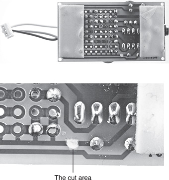
1. Use an X-Acto knife or utility knife to cut the positive voltage line on the back of the prototyping board as shown in Figure B.2. Make sure the copper lamination is completely removed from the cut area.
Figure B.2
Cut the copper pad on the back of the prototyping board.
© 2014 Behnam Salemi, All Rights Reserved.
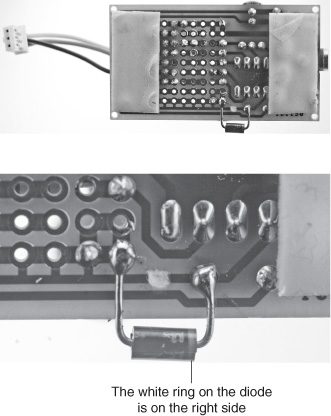
2. Solder the 1N4001 rectifying diode as shown in Figure B.3 to bridge the cut. The image on the right has zoomed to the cut area and the diode.
Caution
Diodes are directional components. Therefore, make sure the white ring on the diode is soldered to the copper pad that connects to leg 1 of the micro-controller (+V). In Figure B.3, the ring is on the right side of the diode.
Figure B.3
Solder the diode. The white ring is on the right side of the diode.