
CHAPTER 4
DIGITAL BRAIN
In the previous chapters, you saw that robots can demonstrate intelligent behavior by doing the following:
![]() Sensing the environment
Sensing the environment
![]() Selecting actions based on the sensed data
Selecting actions based on the sensed data
![]() Performing the selected actions in the environment
Performing the selected actions in the environment
The level of intelligence that a robot demonstrates is determined by how well its selected actions can help the robot to accomplish its goal. The Bug Bot was a simple robot that randomly selected its actions. As a result, it randomly moved in the environment and demonstrated a simple form of bug-like intelligence. The BV-Bot was a more advanced robot. It had sensors to measure the amount of light in its surroundings and intelligently responded by either moving away from the light or moving toward it. The source of its intelligence was built into its hardware; to change its behavior, the BV-Bot’s hardware and wiring needed to be changed.
In general, building robots whose intelligence is built into their hardware and who are capable of performing complex tasks can be quite difficult. The BV-Bot had a simple goal of moving away or moving toward a light source. The simplicity of this goal made it possible to design a robot with simple electronic hardware that could achieve it. However, building a robot whose ability to, for example, drive a car is implemented within its hardware can be quite costly and difficult.
In this chapter and the next one, you will learn another approach to building intelligent robots. This approach is based on implementing the robot’s intelligent behavior in software. You will build a robot called Digital Brain robot, or DB-Bot, whose intelligence is built into a software program that it runs. Similar to BV-Bot, DB-Bot will use sensors to sense its environment and actuators to act in its environment. The difference between BV-Bot and DB-Bot is in the way the actions are selected.
As you saw earlier, the ability to decide on an action is built into the BV-Bot’s hardware, derived from the robot’s sensor data. In DB-Bot, however, the ability to decide what action to perform has been separated from the robot’s hardware. Instead, a micro-controller runs a software program that establishes the connection between sensing and acting by selecting actions based on the values read from the sensors and sending them to the actuators to be performed.
A micro-controller is a general-purpose piece of hardware with multiple analog and digital inputs and outputs. Its behavior is determined by the software program that it runs. DB-Bot’s micro-controller acts as the robot’s digital brain, meaning that you can change the behavior of the robot by changing the software that it runs. The robot’s hardware need not change. This is an important difference between BV-Bot and DB-Bot. Once DB-Bot is built, you do not need to constantly change its hardware to change its behavior. You change the robot’s behavior only by changing the steps in the software that the robot runs. As you will see, controlling the behavior of a robot by using a software program offers a lot of flexibility in terms of selecting actions based on the sensed data.
The major topics covered in this chapter include the following:
![]() A review of the features and capabilities of DB-Bot
A review of the features and capabilities of DB-Bot
![]() Detailed building instructions for DB-Bot
Detailed building instructions for DB-Bot
INTRODUCING DIGITAL BRAIN ROBOT (DB-BOT)
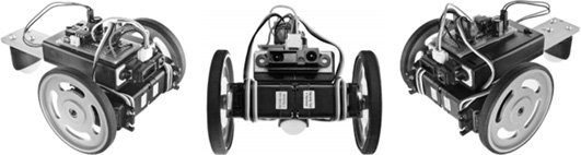
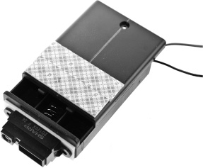
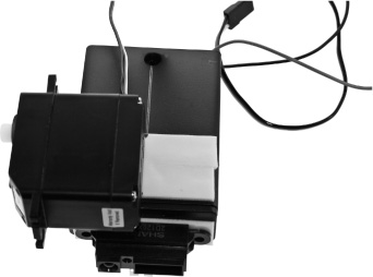
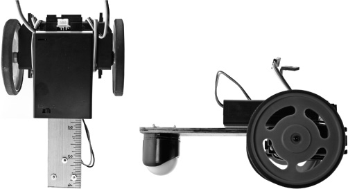
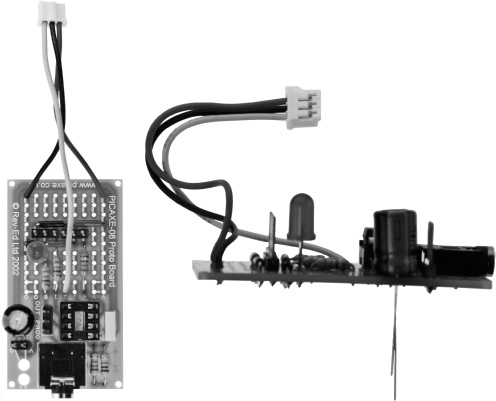
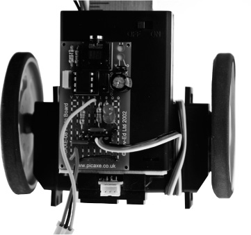
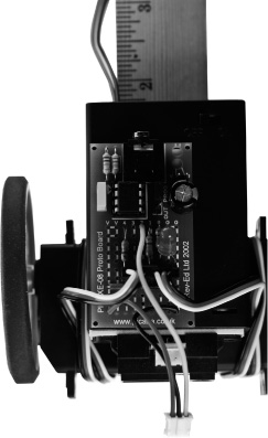
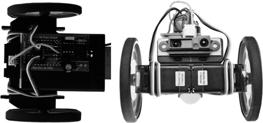
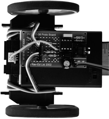
DB-Bot is a simple programmable robot whose intelligent behavior is implemented via a software program. DB-Bot consists of an infra-red distance sensor, introduced in Chapter 3, “Sensing and Acting”; two wheels that are attached to two RC servos with continuous rotation; and a PICAXE micro-controller. Figure 4.1 shows how DB-Bot will look when it is complete.
Figure 4.1
Three views of DB-Bot.
© 2014 Behnam Salemi, All Rights Reserved.
The distance sensor measures the distance between the DB-Bot and any obstacles in front of the robot. The two RC servos move the robot forward and backward when they turn in the same direction, and turn the robot to the right or left when they turn in opposite directions. A caster wheel on the back of the DB-Bot keeps the body of the robot parallel to the ground and allows the rear end of the robot to smoothly follow the robot’s movements.
The role of the micro-controller is to select actions based on the distance data from the distance sensor and send them to the robot actuators to be performed. A program, which you will learn to write in the next chapter, will allow for an intelligent behavior of moving the robot forward in the environment if there is no obstacle in front of the robot and turning the robot to the right to avoid an obstacle if one is detected in front of the robot within a certain distance.
The DB-Bot also has a light emitting diode (LED), which can be turned on and off by the micro-controller. This LED can be used during the operation of the robot to communicate one bit of information, namely “on” or “off.” For example, the robot can turn on the LED when it detects an obstacle in front of it and turn off the LED when no obstacle is detected within a certain distance. This piece of information is also very useful during the development of the program. For example, if you know there is an obstacle in front of the robot but the LED does not turn on, you would know the robot is not working correctly; either the distance sensor is not working or the program does not detect the obstacle (assuming the LED itself is working properly). Similarly, if the LED does turn on but the robot does not turn to the right, that would indicate that the robot is detecting the obstacle but either the program is not sending the turn command to the RC servos or the RC servos are not working correctly. This step-by-step reasoning process to detect and narrow down problems and failures in a program or hardware is called debugging.
DB-Bot is easy to build and work with. The battery holder is also used as the robot base. It allows you to build a robust robot with a minimum number of parts. A prototyping board for a PICAXE micro-controller is used in this project; this simplifies the assembly of the electronics. For ease of use, assembly, and disassembly, the batteries, servo motors, and distance sensor are connected to the micro-controller board using connectors. The battery holder requires three AA alkaline batteries and the on/off switch is part of the battery holder.
BUILDING DB-BOT
You will create the DB-Bot in 21 steps:
1. Installing the distance sensor
2. Installing the RC servo motors
3. Installing the body extension
4. Installing the ball caster
5. Installing the wheels
6. Installing the R1 and R2 resistors
7. Installing the C1 capacitor
8. Installing the micro-controller socket
9. Installing the download jack
10. Installing the programming three-pin header
11. Installing the battery two-pin header
12. Installing the RC servos’ pin headers
13. Installing the distance sensor wiring and connector
14. Installing the LED
15. Installing the large filter capacitor
16. Cleaning the board
17. Installing the micro-controller chip
18. Attaching the battery power connector
19. Installing the prototyping board on the base
20. Inserting the batteries
21. Plugging in the connectors
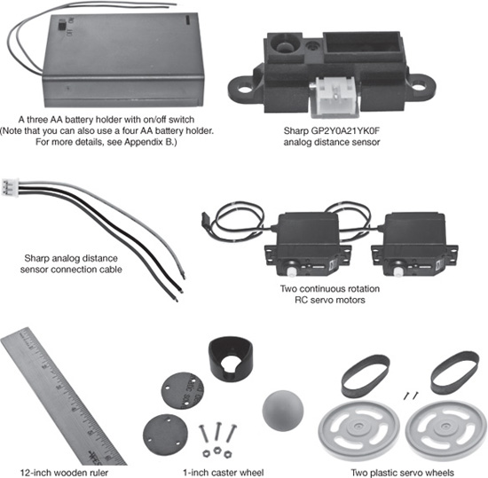
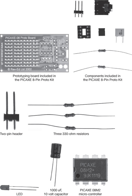
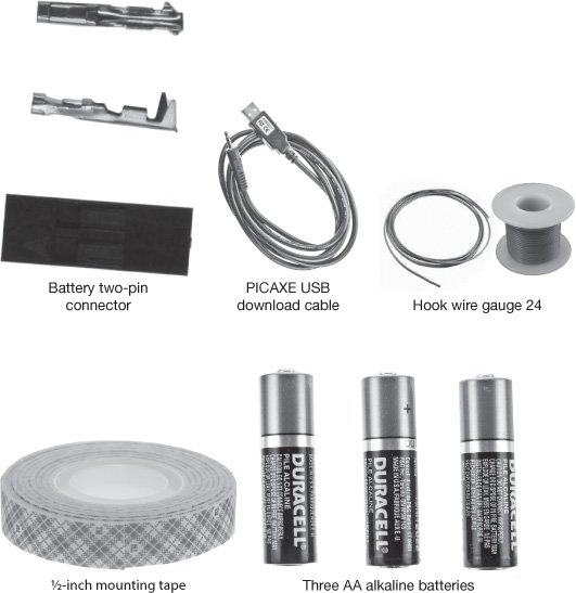
Figure 4.2 provides a complete inventory of the parts needed for building the DB-Bot. The prototyping board and certain other parts are included in the PICAXE 8-Pin Proto Kit. You will be able to purchase these parts online. For detailed information about parts and a list of online vendors who carry them, see Appendix A, “Parts List.”
Figure 4.2
A complete inventory of the parts needed to build the DB-Bot.
© 2014 Behnam Salemi, All Rights Reserved.
Installing the Distance Sensor
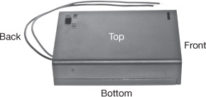
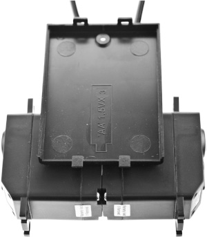
Begin building the DB-Bot by installing the distance sensor on the front side of the battery holder. Figure 4.3 shows the battery holder and the sides selected as the front, back, top, and bottom in this project.
Figure 4.3
The battery holder used as the robot base. The back, top, front, and bottom sides of the base are shown.
© 2014 Behnam Salemi, All Rights Reserved.
To prepare the base for installing the distance sensor, follow these steps:
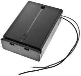
1. Draw a line across the middle of the bottom and front sides of the base, as shown in Figure 4.4.
Figure 4.4
Draw a line across the middle of the bottom and front sides of the base.
© 2014 Behnam Salemi, All Rights Reserved.
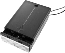
2. Cut a two-inch piece of mounting tape. Attach it to the front side of the base and mark the center of the tape, as shown in Figure 4.5.
Figure 4.5
Attach mounting tape to the front side of the base and mark it as shown.
© 2014 Behnam Salemi, All Rights Reserved.
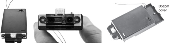
3. Peel off the mounting tape cover and attach the distance sensor to it such that the sensor’s white connector sensor is toward the top of the base, as shown in Figure 4.6. Note in the right-most image in Figure 4.6 that the bottom cover of the base and the on/off switch on the top are visible.
Figure 4.6
Attaching the distance sensor to the robot base.
© 2014 Behnam Salemi, All Rights Reserved.
Note
You can opt to use a four AA battery holder rather than one that holds only three batteries, particularly if you have opted to use larger, more powerful RC servos. For more information, see Appendix B, “Using a Four AA Battery Holder for DB-Bot.”
Installing the RC Servo Motors
The RC servo motors used in this project are built for continuous rotation. Note that servos with continuous rotation are different from normal servos, which turn less than 360 degrees and hold their position. Servos with continuous rotation are ideal for turning the robot’s wheels; it is quite easy to change their speed and the direction of the rotation by the micro-controller. To install the RC servo motors, follow these steps:
1. Cut two pieces of two-inch mounting tape and attach them on the bottom side of the base toward the front end, as shown in Figure 4.7.
Figure 4.7
Attach two pieces of mounting tape to the bottom side of the base.
© 2014 Behnam Salemi, All Rights Reserved.
2. Peel off the mounting tape cover and attach the RC servo to the mounting tape according to the following guidelines:
![]() The rear end of each servo is aligned with the line that you drew across the center of the bottom of the base, as shown in Figure 4.8.
The rear end of each servo is aligned with the line that you drew across the center of the bottom of the base, as shown in Figure 4.8.
Figure 4.8
Align the rear end of each servo with the line you drew across the center of the bottom of the base.
© 2014 Behnam Salemi, All Rights Reserved.
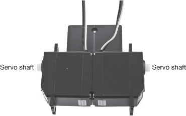
![]() The shafts of both servos are toward the center of the base, as shown in Figure 4.9.
The shafts of both servos are toward the center of the base, as shown in Figure 4.9.
Figure 4.9
The shafts of both servos should be toward the center of the base.
© 2014 Behnam Salemi, All Rights Reserved.
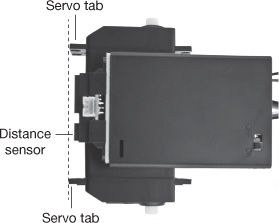
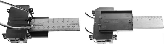
![]() The servos side tabs stick out slightly farther than the distance sensor, as shown in Figure 4.10. These tabs prevent the distance sensor from getting damaged if the robot bumps into something.
The servos side tabs stick out slightly farther than the distance sensor, as shown in Figure 4.10. These tabs prevent the distance sensor from getting damaged if the robot bumps into something.
Figure 4.10
The servo’s side tabs stick out to protect the distance sensor.
© 2014 Behnam Salemi, All Rights Reserved.
Figure 4.11 shows the RC servo motors installed on the bottom side of the base. This is the battery holder lid, which can be detached from the base.
Figure 4.11
The RC servos are installed on the battery holder lid, which can be detached from the base.
© 2014 Behnam Salemi, All Rights Reserved.
Installing the Body Extension
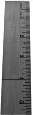
Extending the length of the base will increase the stability of the robot while it is moving. The body extension should be made of a lightweight material such as wood, plastic, or thick cardboard. Here, an easily accessible wooden ruler is used as the body extension. To prepare the body extension, follow these steps:
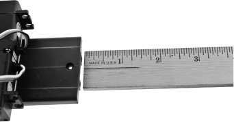
1. Using a pencil, mark the ruler on the 4-inch line, as shown in Figure 4.12.
Figure 4.12
Mark the ruler on the 4-inch line.
© 2014 Behnam Salemi, All Rights Reserved.
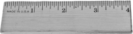
2. Using a wood saw, cut the ruler on the marked line. For this step, be sure you use a pair of safety glasses and gloves, and follow the safety guidelines; the wood saw blade is very sharp and can be dangerous. Figure 4.13 shows the cut body extension.
Figure 4.13
Cut the ruler on the 4-inch line.
© 2014 Behnam Salemi, All Rights Reserved.
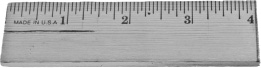
3. Mark the center of the body extension with a line, as shown in Figure 4.14. You will use this line to align the body extension with the line you drew down the middle of the bottom side of the base.
Figure 4.14
Mark the center of the body extension.
© 2014 Behnam Salemi, All Rights Reserved.
4. Place the body extension along the bottom of the base. Mark the edges of the body extension on the bottom side of the base, as shown in Figure 4.15.
Figure 4.15
Mark the edges of the body extension on the bottom side of the base.
© 2014 Behnam Salemi, All Rights Reserved.
5. Cut two pieces of 1.5-inch mounting tape and attach them to the bottom side of the base, as shown in Figure 4.16.
Figure 4.16
Attach mounting tape to the bottom side of the base.
© 2014 Behnam Salemi, All Rights Reserved.
6. Peel off the mounting tape cover and attach the body extension to the mounting tape, as shown in Figure 4.17.
Figure 4.17
Attaching the body extension to the base.
© 2014 Behnam Salemi, All Rights Reserved.
Installing the Ball Caster
The ball caster works like a wheel that turns in all directions. The caster holds the free end of the body extension up and allows the robot to move and turn in any direction. To install the ball caster, follow these steps:
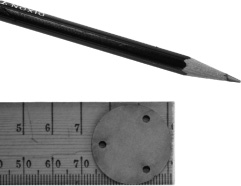
1. Use one of the spacers to mark the three holes on the body extension, as shown in Figure 4.18.
Figure 4.18
Mark the three holes on the body extension.
© 2014 Behnam Salemi, All Rights Reserved.
2. Drill three ![]() -inch holes on the marks, as shown in Figure 4.19.
-inch holes on the marks, as shown in Figure 4.19.
Figure 4.19
Drill holes on the marks.
© 2014 Behnam Salemi, All Rights Reserved.
3. The included screws in the caster kit are size #2. Insert the screws through the caster body, the spacers, and the holes on the body extension; then fasten the nuts. Depending on the size of the wheels used for the RC servos (assembled next), you may need to use one or both spacers included in the caster kit. The goal is to adjust the height of the caster such that the robot base and the body extension are relatively parallel to the ground. If you are using the recommended wheels for the project, use both spacers and the longer screws included in the kit (see Figure 4.20).
Figure 4.20
Screw on the caster body.
© 2014 Behnam Salemi, All Rights Reserved.
4. After tightening the nuts, cut the extra length of the screws using cutter pliers or a hack saw (see Figure 4.21). For this step, make sure you follow safety guidelines and use a pair of safety glasses, as the cut screws may become airborne and can be very dangerous!
Figure 4.21
Trim the caster screws.
© 2014 Behnam Salemi, All Rights Reserved.
5. Insert the ball into the caster body, as shown in Figure 4.22.
Figure 4.22
Inserting the ball into the caster body.
© 2014 Behnam Salemi, All Rights Reserved.
Installing the Wheels
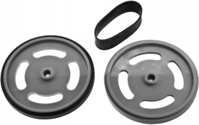
The plastic wheels are installed on the RC servo motors shafts and drive the robot. To install the wheels, follow these steps:
1. Wrap the black rubber bands around the wheels, as shown in Figure 4.23.
Figure 4.23
Wrap the black rubber bands around the wheels.
© 2014 Behnam Salemi, All Rights Reserved.
2. Install the wheels on the RC servos’ shafts. To do so, align each wheel’s center with the corresponding RC servo’s shaft, press them against the shaft, and fasten the screws. Note that you might need to exert some extra force to push the shafts into the wheels’ center holes. Figure 4.24 shows the wheels installed on the RC servo shafts.
Figure 4.24
Attaching the wheels to the RC servos.
© 2014 Behnam Salemi, All Rights Reserved.
Getting Familiar with the PICAXE 08M2 Proto Board
Installing the wheels completes the mechanical assembly of the DB-Bot body. Now you will assemble the micro-controller board. The micro-controller selected for this project is an eight-pin PICAXE 08M2 that is powerful yet simple to work with.
It requires a small number of external components and can be programmed in the BASIC programming language. The PICAXE micro-controller provides a number of documents on how to use and program the chip at www.picaxe.com. For this project, you will assemble a PICAXE from a readily available kit, the PICAXE 8-Pin Proto Kit. You will extend this kit to connect the distance sensor, RC servos, and an LED.
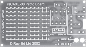
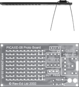
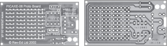
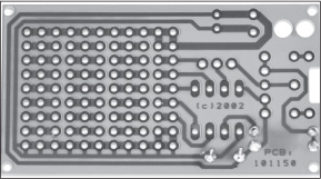
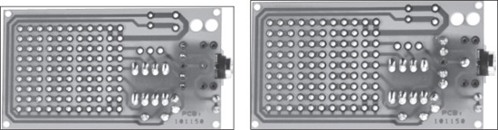
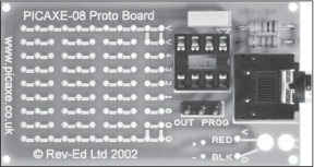
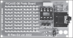
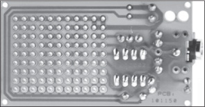
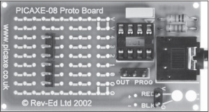
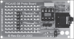
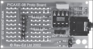
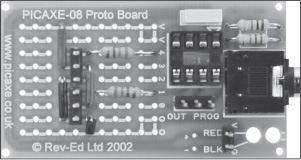
Figure 4.25 shows the PICAXE-08 Proto Board, which is a prototyping board for the PICAXE 08M2 micro-controller. The white rectangles and labels printed on the right side of the board show where the initial components included in the kit should be soldered. These are the components that are required for the micro-controller integrated circuit (IC) to work. The “IC1” label is where the socket for the PICAXE micro-controller chip will be soldered.
R1 and R2 are placeholders for two resistors that are part of the circuit for downloading programs into the PICAXE micro-controller chip. C1 is a placeholder for a capacitor that filters the noise on the voltage line. CT1 shows where the programming jack is soldered. A three-pin header is soldered in the three holes surrounded by the rectangle under which you see the words “OUT” and “PROG.” The “RED,” “V” (for voltage), and “+” labels show where the battery positive pole will be connected, and the “BLK,” “G” (for ground) and “−” labels show where the battery negative pole will be connected.
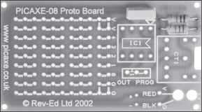
Figure 4.25
The PICAXE-08 Proto Board.
© 2014 Behnam Salemi, All Rights Reserved.
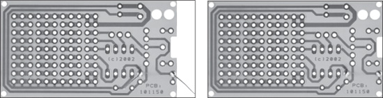
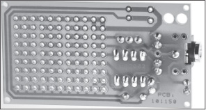
On the left side of the prototyping board are rows of round holes. The thick white line between sets of holes shows that the holes are electrically connected. You can verify this by looking at the back side of the board. You will notice that copper pads electrically connect these holes to each other. The holes labeled “0” (zero) to “4” are connected to pin C.0 to pin C.4, which are the input/output (I/O) pins of the PICAXE micro-controller chip. The input pins are used by the micro-controller to receive data such as distance data from the distance sensor and the output pins are used by the micro-controller to send out data such as commands to move the servos or to turn the LED on or off.
The holes in the top row of the prototyping board, which are connected with white line segments and labeled with the letter “V” on the right, are connected to the positive voltage of the battery. Similarly, the holes in the bottom row, labeled with the letter “G,” are connected to each other and to the negative voltage of the battery. The rest of the holes on the prototyping board are grouped into three connected holes. Each group consists of two white line segments connecting the center hole to the adjacent holes. You will use the left side of the board to connect the distance sensor, RC servo motors, and an LED to the PICAXE micro-controller chip.
Installing the R1 and R2 resistors
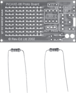
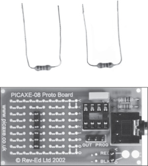
Begin assembly of the micro-controller board by soldering R1 and R2 resistors, which are included in the PICAXE 8 Pin Proto Kit. R1 (with brown, black, and orange rings) is a 10K-ohm resistor and R2 (with red, red, and orange rings) is a 22K-ohm resistor. Both are ¼-watt resistors. To prepare R1 and R2 for installation, follow these steps:
1. Bend the leads of the resistors, as shown in Figure 4.26.
Figure 4.26
Bend the leads of the resistors.
© 2014 Behnam Salemi, All Rights Reserved.
2. Insert the R2 leads into the round holes labeled “R2,” as shown in Figure 4.27.
Figure 4.27
Insert the R2 leads into the appropriate holes.
© 2014 Behnam Salemi, All Rights Reserved.
Tip
After inserting the resistor, hold the resistor in place with your finger and bend the leads outward on the back of the board. Bending the leads will prevent the resistor from falling out of its place when the board is turned for soldering, which makes the soldering easier.
3. Solder the R2 leads and cut the extra leads with a cutter plier, as shown in Figure 4.28.
Figure 4.28
Soldering and trimming the R2 leads.
© 2014 Behnam Salemi, All Rights Reserved.
4. Repeat steps 1–3 for R1. (See Figure 4.29.)
Figure 4.29
Installing the R1 and R2 resistors on the prototyping board.
© 2014 Behnam Salemi, All Rights Reserved.
Installing the C1 Capacitor
The C1 capacitor is a 0.1 microfarad capacitor that is used to filter noise on the voltage line, which can interfere with the operation of the micro-controller. Sources of noise are usually components such as motors, which are present in the RC servos being used in this project. To install the C1 capacitor, follow these steps:
1. Insert the C1 leads into the round holes labeled “C1,” as shown in Figure 4.30.
Figure 4.30
Insert the C1 leads into the appropriate holes.
© 2014 Behnam Salemi, All Rights Reserved.
2. Solder the leads. Then trim the excess leads, as shown in Figure 4.31.
Figure 4.31
Installing the C1 capacitor.
© 2014 Behnam Salemi, All Rights Reserved.
Installing the Micro-Controller Socket
Instead of soldering the micro-controller chip directly on to the prototyping board, first you will install an eight-pin IC socket for the micro-controller onto the board. The IC socket pins will be soldered into the holes designated for the micro-controller. The micro-controller chip is then inserted into the socket. Because the micro-controller is not soldered, you ensure it does not get heat on its pins, which can damage the chip. Also, if the micro-controller chip becomes faulty at any time, it will be easier to pull the chip out of the socket and replace it. To solder the micro-controller socket on the prototyping board, follow these steps:
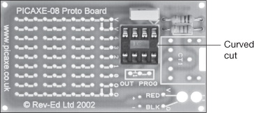
1. Insert the eight-pin IC socket into the holes labeled “IC1.” Notice that there is a small curved cut on the middle of one side of the socket. This curved cut should be placed under the white triangle in the top-right corner of the rectangle that shows the boundary of where the socket should be placed, as shown in Figure 4.32. The triangle shape marks leg 1 of the micro-controller chip.
Figure 4.32
Insert the eight-pin IC socket into the appropriate holes.
© 2014 Behnam Salemi, All Rights Reserved.
2. Bend the two corner pins of the socket, as shown in Figure 4.33. This will prevent the socket from falling out of its place when the board is turned for soldering.
Figure 4.33
Bend the two corner pins of the socket to keep it in place.

© 2014 Behnam Salemi, All Rights Reserved.
3. Solder the socket leads, as shown in Figure 4.34
Figure 4.34
Installing the micro-controller socket.
© 2014 Behnam Salemi, All Rights Reserved.
Installing the Download Jack
PICAXE prototyping board uses a 3.5 mm audio jack to download programs from a PC into the micro-controller chip. To install the download jack, follow these steps:
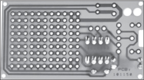
1. Insert the audio jack into the holes labeled “CT1,” as shown in Figure 4.35.
Figure 4.35
Insert the audio jack into the appropriate holes.
© 2014 Behnam Salemi, All Rights Reserved.
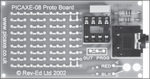
2. Solder the leads, as shown in Figure 4.36.
Figure 4.36
Installing the download jack.
© 2014 Behnam Salemi, All Rights Reserved.
Installing the Programming Three-Pin Header
The three-pin header will be installed in the three holes surrounded by the rectangle under which you see the words “OUT” and “PROG,” as shown in Figure 4.37. The three-pin header allows pin C.0 of the micro-controller to be used for downloading programs to the micro-controller or as a normal output. The output pin C.0 of the micro-controller is connected to the center pin of the three-pin header. When the center pin is shorted to the pin header on the left, marked “OUT,” pin C.0 will be a normal output. When the center pin is shorted to the pin header on the right, marked “PROG,” pin C.0 will be used for downloading programs to the micro-controller. To install the three-pin header, follow these steps:
1. Insert the three-pin header in the appropriate holes, as shown in Figure 4.37.
Figure 4.37
Insert the three-pin header in the appropriate holes.
© 2014 Behnam Salemi, All Rights Reserved.
2. Solder the leads, as shown in Figure 4.38.
Figure 4.38
Installing the three-point header.
© 2014 Behnam Salemi, All Rights Reserved.
Installing the Battery Two-Pin Header
A two-pin header is used to connect the battery voltage to the prototyping board. To install the two-pin header, follow these steps:
1. Insert the two-pin header in the holes labeled “RED” and “BLK,” as shown in Figure 4.39.
Figure 4.39
Insert the two-pin header in the appropriate holes.
© 2014 Behnam Salemi, All Rights Reserved.
2. Solder the leads, as shown in Figure 4.40.
Figure 4.40
Installing the battery two-pin header.
© 2014 Behnam Salemi, All Rights Reserved.
At this point, all necessary components for the micro-controller to work are soldered on the prototyping board. However, nothing is connected to the I/O pins of the micro-controller yet. Next, you will connect the distance sensor, RC servos, and an LED to the micro-controller.
Installing the RC Servos’ Pin Headers
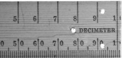
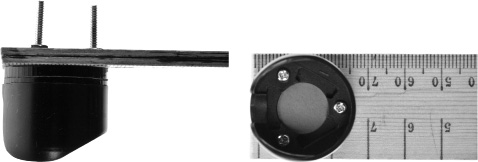
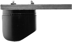
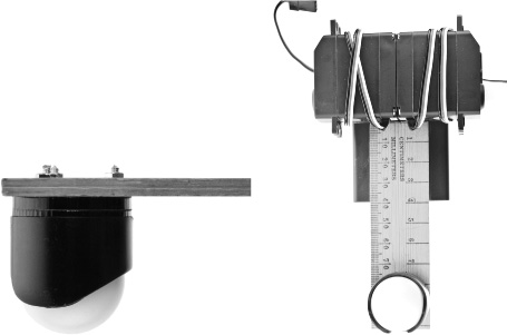
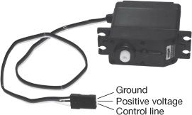
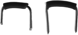
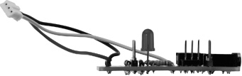
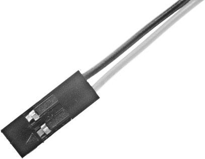
The RC servos use three wires for their operation. Figure 4.41 shows an RC servo and its three wires, which are attached to a connector. The middle wire, which is usually red, connects to the positive voltage line. The black wire on the top connects to the negative voltage line (ground). The white or yellow wire on the bottom is the control line, which connects to an output pin of the micro-controller.
Figure 4.41
An RC servo and its three wires.
© 2014 Behnam Salemi, All Rights Reserved.
Two three-pin headers will be installed on the prototyping board to connect the RC servos to the micro-controller, as described in the following steps:
1. Insert two three-pin headers into the prototyping board holes, as shown in Figure 4.42.
Figure 4.42
Insert two three-pin headers into the prototyping board holes.
© 2014 Behnam Salemi, All Rights Reserved.
2. Solder them, as shown in Figure 4.43.
Figure 4.43
Solder the three-pin headers.
© 2014 Behnam Salemi, All Rights Reserved.
3. Bend the leads of two 330-ohm resistors, as shown in Figure 4.44.
Figure 4.44
Bend the leads of two 330-ohm resistors.
© 2014 Behnam Salemi, All Rights Reserved.
4. Insert them into the holes of the prototyping board (see Figure 4.45) and solder them. These resistors connect pins C.1 and C.4 of the micro-controller to control lines of the RC servo motors, which is the white wire in the servo cable.
Figure 4.45
The resistors connect the servos’ control line pin headers to C.1 and C.4 output pins.
© 2014 Behnam Salemi, All Rights Reserved.
5. To connect the center pin header to the positive voltage, cut and bend two ½-inch pieces of hook wire, as shown in Figure 4.46.
Figure 4.46
Cut and bend two ½-inch pieces of hook wire.
© 2014 Behnam Salemi, All Rights Reserved.
6. Insert the pieces of wire into the prototyping board (see Figure 4.47) and solder them.
Figure 4.47
Connecting the servos’ center pin headers to the positive voltage.
© 2014 Behnam Salemi, All Rights Reserved.
Note
As you see, one of these wires goes over a resistor. Therefore, it is important that the wire has an isolating cover to isolate the wire and the resistor’s lead. If you have the choice of color, choose the red hook wire for the positive voltage.
7. To connect the servos’ third pin header to the negative voltage (ground), cut and bend two more pieces of hook wires—one to ⅓ of an inch and the other to ½ an inch.
8. Insert them into the prototyping board (see Figure 4.48) and solder them. If you have the choice of color, choose the black hook wire for the negative voltage.
Figure 4.49 shows a larger view of the hook wires soldered on the prototyping board.
Figure 4.48
Connecting the servos’ bottom pin headers to the ground voltage.
© 2014 Behnam Salemi, All Rights Reserved.
Figure 4.49
Installing the RC servo pin headers.

© 2014 Behnam Salemi, All Rights Reserved.
Installing the Distance Sensor Wiring and Connector
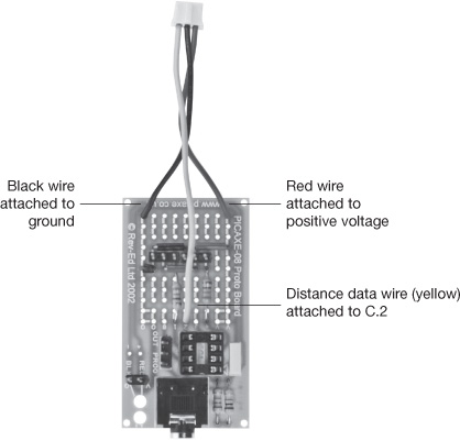
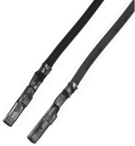
Figure 4.50 shows the distance sensor connector. The connector has a bump on one side so it can only be plugged into the distance sensor one way. The red and black wires attach to positive voltage and ground, respectively, to provide voltage to the distance sensor and the yellow wire carries the distance data in the form of a voltage level. The yellow wire will be connected to a micro-controller input.
Figure 4.50
The distance sensor connector.

© 2014 Behnam Salemi, All Rights Reserved.
To install the connector, follow these steps:
1. Peel off about ¼ of an inch of the cover from the end of the yellow wire.
2. Insert the yellow wire directly to the pin C.2 input of the micro-controller and solder it, as shown in Figure 4.51.
Figure 4.51
Installing the distance sensor cable.
© 2014 Behnam Salemi, All Rights Reserved.
3. Shorten the red and black wires about an inch so that there is not too much slack when the wires are extended (see Figure 4.51).
4. Peel off about ¼ of an inch of the cover from the end of the red and black wires.
5. Insert the red and black wires into the positive voltage (V) and ground (G) holes, respectively, and solder them, as shown in Figure 4.51.
Installing the LED
The LED will be connected to the pin C.0 output of the micro-controller through a 330-ohm resistor. To install the LED, follow these steps:
1. Insert a 330-ohm resistor into the holes of the prototyping board (see Figure 4.52) and solder the leads. As you can see, one side of the resistor connects to the pin C.0 of the micro-controller.
Figure 4.52
Connecting the 330-ohm resistor to the output pin C.0.
© 2014 Behnam Salemi, All Rights Reserved.
2. Bend the shorter lead of the LED, as shown in Figure 4.53. The longer lead is called the anode and the shorter lead is called the cathode.
Figure 4.53
Bend the leads of the LED as shown here.

© 2014 Behnam Salemi, All Rights Reserved.
3. Insert the LED leads into the holes of the prototyping board such that the cathode connects to the ground and the anode connects to the free end of the resistor soldered in the previous step (see Figure 4.54). Figure 4.55 shows the side view of the board after the LED is installed.
Figure 4.54
Insert the LED leads into the holes of the prototyping board.
© 2014 Behnam Salemi, All Rights Reserved.
Figure 4.55
The side view of the board after installing the LED.
© 2014 Behnam Salemi, All Rights Reserved.
Installing the Large Filter Capacitor
To reduce the noise on the power lines, you will install a large capacitor in addition to the C1 capacitor that was installed earlier. The large capacitor is a 10 volt 1000 uF electrolyte capacitor. To install the capacitor, do the following:
1. Insert the negative and positive leads of the capacitor into the holes labeled “+” and “−,” as shown in Figure 4.56.
2. Solder the capacitor’s leads and cut the extra leads with a cutter plier.
Figure 4.56
Installing the large capacitor filter.
© 2014 Behnam Salemi, All Rights Reserved.
Cleaning the Board
Now that all the components are soldered on the prototyping board, the next step is to clean the soldering flux from the back of the board. The soldering flux can create unwanted connectivity among adjacent components, causing the circuit not to work. Use a brush and rubbing alcohol to remove the soldering flux.
Installing the Micro-Controller Chip
The last component installed on the board is the micro-controller chip. To install the micro-controller chip, do the following:
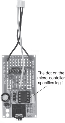
1. Align the eight legs of the micro-controller chip with the eight-pin socket such that the dot on top of the micro-controller chip is in front of the white printed rectangle on the prototyping board (see Figure 4.57) and press the chip inside the socket. The dot specifies the position of leg 1 of the micro-controller.
Figure 4.57
Installing the micro-controller chip.
© 2014 Behnam Salemi, All Rights Reserved.
Attaching the Battery Power Connector
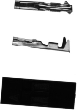
The voltage of the battery holder is available through its red and black wires. To connect these two wires to the prototyping board, you will use a two-pin female connector, as shown in Figure 4.58.
Figure 4.58
A two-pin female connector connects the battery holder wires to the prototyping board.
© 2014 Behnam Salemi, All Rights Reserved.
To attach the connector to the voltage wires, follow these steps:
1. Remove about ⅛ of an inch from the wire’s cover from the free end of the battery holder wires.
2. Attach the pins to the end of the wire, as shown in Figure 4.59. Use pliers to fold and press the tabs onto the wires.
Figure 4.59
Attach the pins to the end of the wire.
© 2014 Behnam Salemi, All Rights Reserved.
3. Insert the pins into the female connector housing, as shown in Figure 4.60. The pins will be latched into the housing.
Figure 4.60
Attaching the battery power connector.
© 2014 Behnam Salemi, All Rights Reserved.
Installing the Prototyping Board on the Base
Now it is time to attach the assembled prototyping board to the base. Later, the distance sensor, RC servos, and power connectors will be plugged into the board. To attach the prototyping board to the base, follow these steps:
1. Cut two pieces of 1-inch mounting tape and attach them to the back of the prototyping board, as shown in Figure 4.61.
Figure 4.61
Attach two pieces of 1-inch mounting tape to the back of the prototyping board.

© 2014 Behnam Salemi, All Rights Reserved.
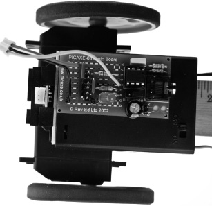
2. Peel off the mounting tape cover and attach the prototyping board to the corner of the base, as shown in Figure 4.62. This will leave enough space around the on/off switch.
Figure 4.62
Attaching the assembled prototyping board to the base.
© 2014 Behnam Salemi, All Rights Reserved.
Inserting the Batteries
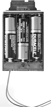
The battery holder requires three AA alkaline batteries. Open the battery holder lid and insert three new batteries in the correct direction, as shown in Figure 4.63. Each battery has 1.5V, which will allow the robot to operate with 4.5V.
Figure 4.63
Inserting the batteries.
© 2014 Behnam Salemi, All Rights Reserved.
Plugging in the Connectors
The final step of the DB-Bot assembly is to connect the distance sensor, RC servos, and the power connector to the prototyping board. Follow these steps:
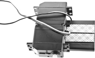
1. Wrap the left RC servo cable around the servo, pass the free end of the cable through the formed loop, and tighten the cable. Then insert the cable’s three-pin connector into the left three-pin servo header on the prototyping board, as shown in Figure 4.64. The white wire of the servo carries the control signal and should be connected to the pin header that is connected to the resistor. The red and black wires are for power and will be connected to positive and negative (ground) voltages, respectively.
Figure 4.64
Connect the left RC servo.
© 2014 Behnam Salemi, All Rights Reserved.
2. Wrap the right RC servo cable around the servo, pass the free end of the cable through the formed loop, and tighten the cable. Then insert its three-pin connector into the right three-pin servo header on the prototyping board as shown in Figure 4.65. The white wire of the servo carries the control signal and should be connected to the pin header that is attached to the resistor. The red and black wires are for power and will be connected to positive and negative (ground) voltages, respectively.
Figure 4.65
Connect the right RC servo.
© 2014 Behnam Salemi, All Rights Reserved.
3. Insert the distance sensor connector into the distance sensor, as shown in Figure 4.66. The connector can be plugged into the sensor male connector in only one direction.
Figure 4.66
Connect the distance sensor.
© 2014 Behnam Salemi, All Rights Reserved.
4. Connect the female battery connector to the battery pin headers, as shown in Figure 4.67. The red wire must connect to the pin labeled “+,”“V,” or “RED,” and the black wire must connect to the pin labeled “−,” “G,” or “BLK”; otherwise, the circuit will not work.
Figure 4.67
The battery connector is plugged into the prototyping board.
© 2014 Behnam Salemi, All Rights Reserved.
SUMMARY
In this chapter, you built a simple programmable robot called the DB-Bot. The DB-Bot had a sensor to measure distance, two wheels to move freely in the environment, an LED and a micro-controller. However, a micro-controller without a software program does not do anything!
In the next chapter, you will learn how to program the DB-Bot and implement intelligent behavior in software. The software program will enable the DB-Bot micro-controller to read the distance data from the distance sensor, make decisions, send commands to the RC servos to turn each wheel at a specified speed and direction, and turn the LED on and off.