
CHAPTER 21
Network Troubleshooting
The CompTIA Network+ certification exam expects you to know how to
• 1.1 Compare and contrast the Open Systems Interconnection (OSI) model layers and encapsulation concepts
• 2.3 Given a scenario, configure and deploy common Ethernet switching features
• 5.1 Explain the network troubleshooting methodology
• 5.2 Given a scenario, troubleshoot common cable connectivity issues and select the appropriate tools
• 5.3 Given a scenario, use the appropriate network software tools and commands
• 5.5 Given a scenario, troubleshoot general networking issues
To achieve these goals, you must be able to
• Describe appropriate troubleshooting tools and their functions
• Analyze and discuss the troubleshooting process
• Resolve common network issues
Have you ever seen a tech walk up to a network and seem to know all the answers, effortlessly typing in a few commands and magically making the system or network work? I’ve always been intrigued by how they do this. Observing such techs over the years, I’ve noticed that they tend to follow the same steps for similar problems—looking in the same places, typing the same commands, and so on.
When someone performs a task the same way every time, I figure they’re probably following a plan. They understand what tools they have to work with, and they know where to start and what to do second and third and fourth until they find the problem.
This chapter’s lofty goal is to consolidate my observations on how these “übertechs” fix networks. I’ll show you the primary troubleshooting tools and help you formulate a troubleshooting process and learn where to look for different sorts of problems. Then you’ll apply this knowledge to resolve common network issues.
Test Specific
Troubleshooting Tools
While working through the process of finding a problem’s cause, you sometimes need tools. These tools are the software and hardware tools that provide information about your network and enact repairs. I covered a number of tools already: hardware tools like cable testers and crimpers and software utilities like ping and tracert. The trick is knowing when and how to use these tools to solve your network problems.

CAUTION No matter what the problem, always consider the safety of your data first. Ask yourself this question before performing any troubleshooting action: “Can what I’m about to do potentially damage my data?”
Almost every new networking person I teach will, at some point, ask me: “What tools do I need to buy?” My answer shocks them: “None. Don’t buy a thing.” It’s not so much that you don’t need tools, but rather that different networking jobs require wildly different tools. Plenty of network techs never crimp a cable. An equal number never open a system. Some techs do nothing all day but pull cable. The tools you need are defined by your job.
This answer is especially true with software tools. Almost all the network problems I encounter in established networks don’t require me to use any tools other than the classic ones provided by the operating system. I’ve fixed more network problems with ping, for example, than with any other single tool. As you gain skill in this area, you’ll find yourself hounded by vendors trying to sell you the latest and greatest networking diagnostic tools. You may like these tools. All I can say is that I’ve never needed a software diagnostics tool that I had to purchase.
Hardware Tools
In multiple chapters in this book, you’ve read about tools used to configure a network. These hardware tools include cable testers, TDRs, OTDRs, certifiers, voltage event recorders, protocol analyzers, cable strippers, multimeters, tone probes/generators, and punchdown tools. Some of these tools can also be used in troubleshooting scenarios to help you eliminate or narrow down the possible causes of certain problems. Let’s review the tools as listed in the CompTIA Network+ exam objectives (plus a couple I think you should know).

EXAM TIP Read this section! The CompTIA Network+ exam is filled with repair scenarios, and you must know what every tool does and when to use it.
Cable Testers, TDRs, and OTDRs
The vast majority of cabling problems occur when the network is first installed or when a change is made. Once a cable has been made, installed, and tested, the chances of it failing are pretty small compared to all of the other network problems that might take place. If you’re having trouble connecting to a resource or experiencing performance problems after making a connection, a bad cable likely isn’t the culprit. Broken cables don’t make intermittent problems, and they don’t slow down data. They make permanent disconnects.
Network techs define a “broken” cable in numerous ways. First, a broken cable might have an open circuit, where one or more of the wires in a cable simply don’t connect from one end of the cable to the other. The signal lacks continuity. Second, a cable might have a short, where one or more of the wires in a cable connect to another wire in the cable. (Within a normal cable, no wires connect to other wires.)
EXAM TIP The CompTIA Network+ exam objectives use the terms open/short. More commonly, techs would refer to these issues as open circuits and short circuits.
Third, a cable might have a wire map problem, where one or more of the wires in a cable don’t connect to the proper location on the jack or plug. This can be caused by improperly crimping a cable, for example. Fourth, the cable might experience crosstalk, where the electrical signal bleeds from one wire pair to another, creating interference.
Fifth, a broken cable might pick up noise, spurious signals usually caused by faulty hardware or poorly crimped jacks. Finally, a broken cable might have impedance mismatch. Impedance is the natural electrical resistance of a cable. When cables of different types—think thickness, composition of the metal, and so on—connect and the flow of electrons is not uniform, it can cause a unique type of electrical noise, called an echo.
Network technicians use three different devices to deal with broken cables. Cable testers can tell you if you have a continuity problem or if a wire map isn’t correct (Figure 21-1). Time domain reflectometers (TDRs) and optical time domain reflectometers (OTDRs) can tell you where the break is on the cable (Figure 21-2). A TDR works with copper cables and an OTDR works with fiber optics, but otherwise they share the same function. If a problem shows itself as a disconnect and you’ve first checked easier issues that would manifest as disconnects, such as loss of permissions, an unplugged cable, or a server shut off, then think about using these tools.
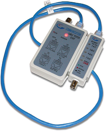
Figure 21-1 Classic cable tester
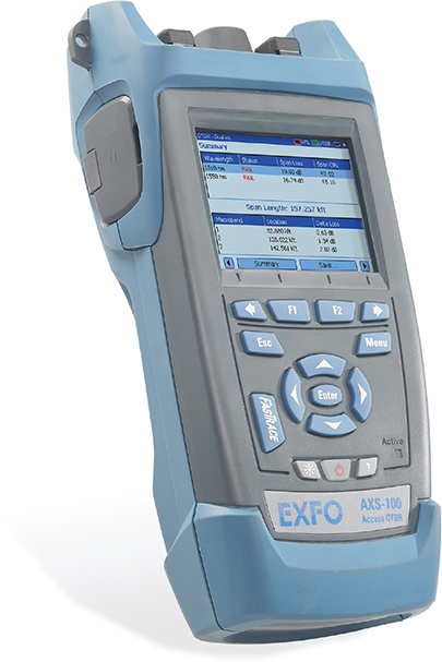
Figure 21-2 An EXFO AXS-100 OTDR (photo courtesy of EXFO)
Certifiers
Certifiers test a cable to ensure that it can handle its rated amount of capacity. When a cable is not broken but it’s not moving data the way it should, turn to a certifier. Look for problems that cause a cable to underperform. A bad installation might increase crosstalk, attenuation, or interference. A certifier can pick up an impedance mismatch as well. Most of these problems show up at installation, but running a certifier to eliminate cabling as a problem is never a bad idea. Don’t use a certifier for disconnects, only slowdowns. All certifiers need some kind of loopback adapter on the other end of the cable run to provide termination and return of a signal. A loopback adapter is a small device with a single port.
Fiber Light Meter
The extremely transparent fiber-optic cables allow light to shine but have some inherent impurities in the glass that can reduce light transmission. Dust, poor connections, and light leakage can also degrade the strength of light pulses as they travel through a fiber-optic run. To measure the amount of light loss, technicians use an optical power meter, also referred to as a fiber light meter (see Figure 21-3).

Figure 21-3 FiberLink® 6650 Optical Power Meter (photo courtesy of Communications Specialties, Inc.)
EXAM TIP The CompTIA Network+ exam objectives use the term fiber light meter. The more accurate term in this context is either power meter or optical power meter. You may see any of these terms on the exam.
The fiber light meter system uses a high-powered source of light at one end of a run and a calibrated detector at the other end. This measures the amount of light that reaches the detector.
Voltage Quality Recorder/Temperature Monitor
Networks need the proper temperature and adequate power, but most network techs tend to view these issues as outside of the normal places to look for problems. That’s too bad, because both heat and power problems invariably manifest themselves as intermittent problems. Look for problems that might point to heat or power issues: server rooms that get too hot at certain times of the day, switches that fail whenever an air conditioning system kicks on, and so on. You can use a voltage quality recorder and a temperature monitor to monitor server rooms over time to detect and record issues with electricity or heat, respectively. They’re great for those “something happened last night” types of issues.
Cable Strippers and Snips
A cable stripper (Figure 21-4) helps you to make UTP cables. You’ll need a crimping tool (a cable crimper) as well. Cable strippers include a tool for cutting wires. You can also cut wires with a snip, a tool designed to cut through metal like wires. You don’t need these tools to punch down 66- or 110-blocks. You would use a punchdown tool for that (as described in a bit).

Figure 21-4 A cable stripping and crimping tool
Multimeters
Multimeters test voltage (both AC and DC), resistance, and continuity. They are the unsung heroes of cabling infrastructures because no other tool can tell you how much voltage is on a line. They are also a great fallback for continuity testing when you don’t have a cable tester handy.

NOTE There’s an old adage used by carpenters and other craftspeople that goes, “Never buy cheap tools.” Cheap tools save you money at the beginning, but they often break more readily than higher-quality tools and, more importantly, make it harder to get the job done. This adage definitely applies to multimeters! You might be tempted to go for the $10 model that looks pretty much like the $25 model, but chances are the leads will break or the readings will lie on the cheaper model. Buy a decent tool, and you’ll never have to worry about it.
Tone Probes and Tone Generators
Tone probes and their partners, tone generators, have only one job: to help you locate a particular cable. You’ll never use a tone probe without a tone generator. You’ll recall these from way back in Chapter 5, when we explored the classic Fox and Hound toner set from Triplett Corporation. The tone generator connects to a cable. The tone probe scans the wires and ports on the far end to see which connects.
Punchdown Tools
Punchdown tools (Figure 21-5) put UTP wires into 66- and 110-blocks. The only time you would use a punchdown tool in a diagnostic environment is a quick repunch of a connection to make sure all the contacts are properly set.
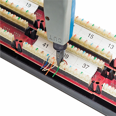
Figure 21-5 A punchdown tool in action
Try This!
Software Tools
Make the CompTIA Network+ exam (and real life) easier by separating your software tools into two groups: those that come built into every operating system and those that are third-party tools. Typical built-in tools are hostname, tracert/traceroute, ipconfig/ifconfig/ip, arp, ping, arping, pathping, nslookup/dig, mtr, route, and netstat/ss. Third-party tools fall into the categories of packet sniffers, port scanners, throughput testers, and looking glass sites. And because nothing is quite as simple as built-in vs. third-party, we have to add terminal emulators, which are both. We’ll start with terminal emulators.
Try This!
The CompTIA Network+ exam tests your ability to recognize the output from all of the built-in tools (except arping, mtr, and ss). Take some time to memorize example outputs from all of these tools.
Terminal Emulator
Network techs rely on a command-line interface (CLI) for troubleshooting and configuring at all levels, from simple commands to complex scripts. A CLI is a shell, a way to interact with an operating system, just as a graphical user interface (GUI) is a shell. A terminal emulator program enables access to various CLI shells.
Every modern operating system offers one or more terminal emulators. macOS has Terminal.app, for example. The terminal emulator enables you to modify how the CLI text renders. This manifests as different colors and fonts on the screen, in the simplest sense, to compatibility modes for working with legacy systems.
hostname
The hostname utility does exactly what it says on the label—it prints out the hostname of the current system. There are other places to check the hostname (especially in the GUI), but being able to check the hostname from the shell may save your skin if you’re troubleshooting over SSH. The command is also useful if you have to run a script on many systems that needs access to each system’s hostname (for example, to gather information about how many systems are configured and save the details in a file named for each host).
The utility isn’t terribly interesting on its own, but here’s sample hostname output from a Windows system:
![]()
tracert/traceroute
The traceroute utility (the command in Windows is tracert) is used to trace all of the routers between two points. Use traceroute to diagnose where the problem lies when you have problems reaching a remote system. If a traceroute stops at a certain router, you know the problem is either the next router or the connections between them.
When sending a traceroute, it’s important to keep a significant difference between Windows and UNIX/Linux systems in mind. Windows tracert sends only ICMP packets, while UNIX/Linux traceroute sends UDP datagrams by default, but can also send TCP segments.
Because many routers block ICMP packets, if traceroute fails from a Windows system, running it on a Linux or UNIX system may return more complete results. The reverse is true as well. Routers could be blocking UDP (many in fact do block UDP-based trace-routes), and then the ICMP version becomes the more informative one.
Here’s sample traceroute output:

The traceroute command defaults to either IPv4 or IPv6 depending on the OS installed and the network connection installed. In either case, you can force traceroute to use IPv6 with the -6 flag. In addition, on macOS/Linux, you can use the IPv6-specific traceroute6 command.
ipconfig/ifconfig/ip
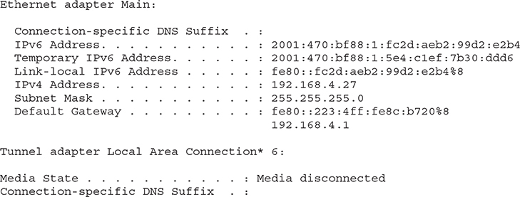
The ipconfig (Windows), ifconfig (macOS and UNIX), and ip (Linux) utilities tell you almost anything you want to know about a computer’s IP settings. Make sure you know that typing ipconfig alone only gives basic information. Typing ipconfig /all gives detailed information (like DNS servers and MAC address).
Here’s sample ipconfig output:
And here’s sample ifconfig output:
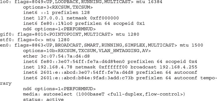
And finally, here’s Linux’s ip address output:
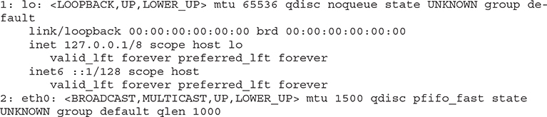
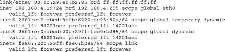
![]()
SIM You get three for the price of one with sims in this chapter! Check out the Chapter 21, “Who Made That NIC,” sims at https://totalsem.com/008. You’ll find a Show!, a Click!, and a Challenge! on the subject that will help you solidify the usefulness of the tools for your technician’s toolbox.
arp
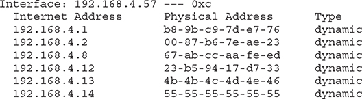
Computers use Address Resolution Protocol (ARP) to resolve IP addresses to MAC addresses. As the computer learns various MAC addresses on its LAN, it jots them down in the ARP table. When Computer A wants to send a message to Computer B, it determines B’s IP address and then checks the ARP table for a corresponding MAC address.
The arp utility enables you to view and change the ARP table on a computer. Here’s sample output from arp –a:
ping, pathping, and arping
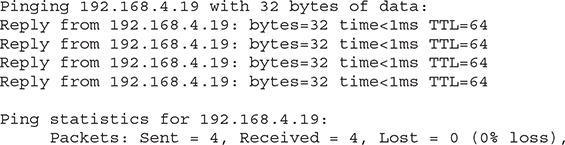
The ping utility uses Internet Message Control Protocol (ICMP) packets to query by IP address or by name. It works across routers, so it’s generally the first tool used to check if a system is reachable. Unfortunately, many devices block ICMP packets, so a failed ping doesn’t always point to an offline system.
The ping utility defaults to either IPv4 or IPv6 depending on the OS installed and the network connection installed. In either case, you can force ping to use IPv6 with the -6 flag. In addition, on macOS/Linux, you can use the IPv6-specific ping6 command.
Here’s sample ping output:
![]()
If ping doesn’t work, you can try arping, which uses ARP frames instead of ICMP packets. The only downside to arping is that ARP frames do not cross routers because they only consist of frames, and never IP packets, so you can only use arping within a broadcast domain. Windows does not have arping. UNIX and UNIX-like systems, on the other hand, support the arping utility.
Next is sample arping output:
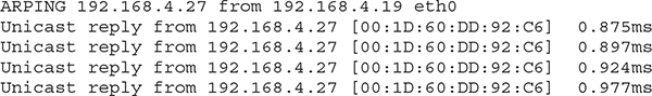
EXAM TIP The ping command has the word Pinging in the output. The arping command has the word ARPING. You’ll see ping on the CompTIA Network+ exam; you won’t see arping.
The ping and traceroute utilities are excellent examples of connectivity software, applications that enable you to determine if a connection can be made between two computers.
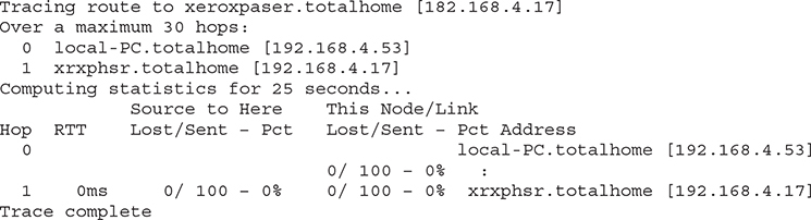
Microsoft has a utility called pathping that combines the functions of ping and trace-route and adds some additional functions.
Here is sample pathping output:
nslookup/dig
The nslookup (all operating systems) and dig (macOS/UNIX/Linux) utilities help diagnose DNS problems. These tools are very powerful, but the CompTIA Network+ exam won’t ask you more than basic questions, such as how to use them to see if a DNS server is working. When working on Windows systems, the nslookup utility is your only choice by default. On macOS/UNIX/Linux systems, you should prefer the dig utility. Both utilities will help in troubleshooting your DNS issues, but dig provides more verbose output by default. You need to be comfortable working with both utilities when troubleshooting networks.
EXAM TIP Running the networking commands several times will help you memorize the functions of the commands as well as the syntax. The CompTIA Network+ exam is also big on the switches available for various commands, such as ipconfig /all.
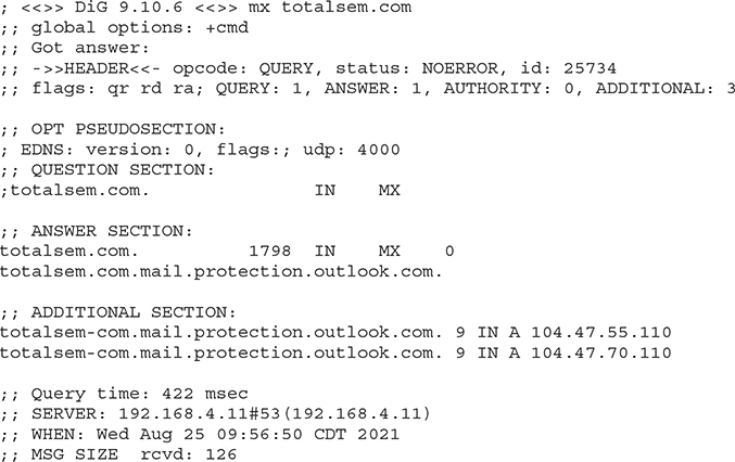
Following is an example of the dig command:
dig mx totalsem.com
This command says, “Show me all the MX records for the totalsem.com domain.”
Here’s the output for that dig command:
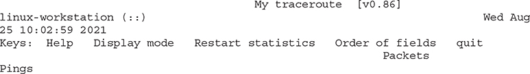
mtr
My Traceroute (mtr) is a dynamic (keeps running) equivalent to traceroute; like pathping it combines traceroute and ping. mtr is a UNIX/Linux tool; you can find a Windows version called WinMTR, but you should run the native mtr instead through the Windows Subsystem for Linux (WSL) in Windows 10/11. Both pathping and mtr run a traceroute all along a path, but pathping stops when it hits a site that doesn’t respond, whereas mtr keeps going to the end if it can. Both tools help pinpoint problems, but mtr is more robust and precise.
Here’s a sample of mtr output:
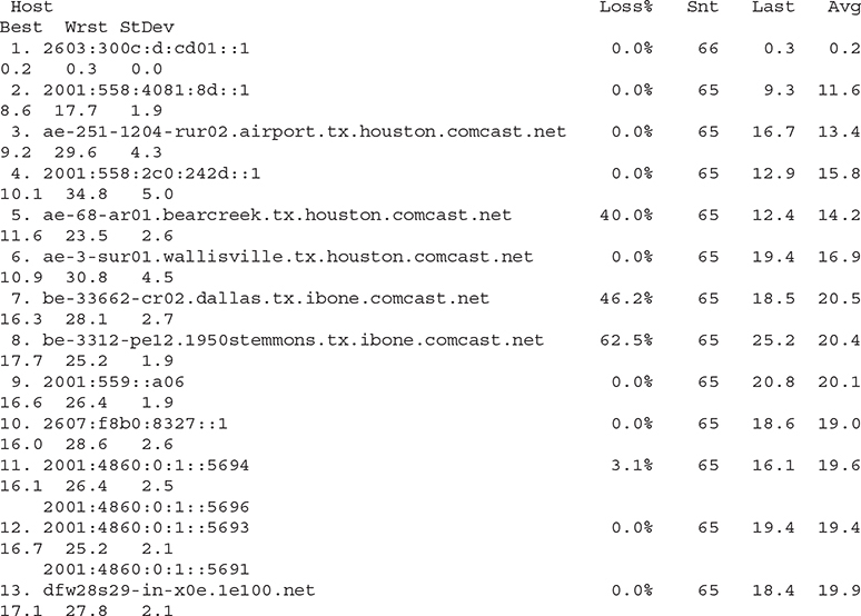
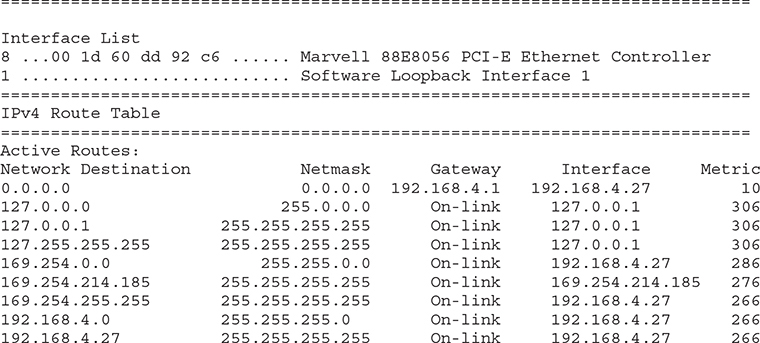
route
The route utility enables you to display and edit the local system’s routing table. To show the routing table, just type route print or netstat -r.
Here’s a sample of route print output:
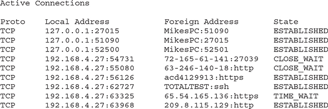
netstat and ss
The netstat utility displays information on the current state of all the running IP processes on a system. It shows what sessions are active and can also provide statistics based on ports or protocols (TCP, UDP, and so on). Typing netstat by itself only shows current sessions. Typing netstat –r shows the routing table (identical to Windows’ route print). If you want to know about your current sessions, netstat is the tool to use.
Here’s sample netstat output:
Windows still comes with netstat, but the ss utility—part of the iproute2 utility suite, along with ip and all its switches—has completely eclipsed it on the Linux side. The ss utility is faster and more powerful than netstat. Unlike netstat, however, you won’t find ss on the CompTIA Network+ exam. Here’s sample output from ss, filtered to show only TCP connections:

EXAM TIP You won’t see ss or iproute2 on the CompTIA Network+ exam.
Packet Sniffer/Protocol Analyzer
A packet sniffer, as you’ll recall from Chapter 20, intercepts and logs network packets, a process called packet capture. You have many choices when it comes to packet sniffers. Some sniffers come as programs you run on a computer, while others manifest as dedicated hardware devices. Most packet sniffers come bundled with a protocol analyzer, the tool that takes the sniffed information and figures out what’s happening on the network. Arguably, the most popular GUI packet sniffer and protocol analyzer is Wireshark (Figure 21-6).
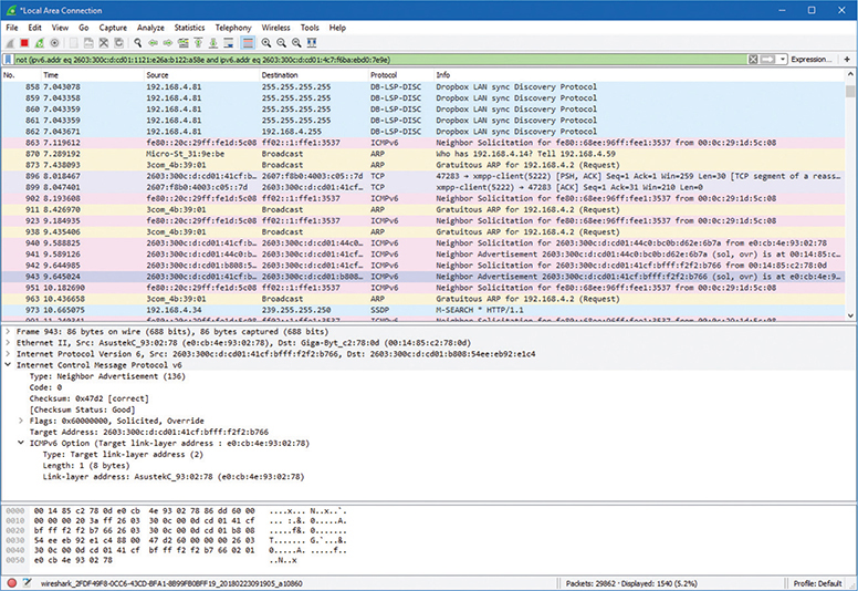
Figure 21-6 Wireshark in action
Port Scanners
As you’ll recall from back in Chapter 18, a port scanner is a program that probes ports on another system, logging the state of the scanned ports. These tools are used to look for unintentionally opened ports that might make a system vulnerable to attack. As you might imagine, they also are used by hackers to break into systems.
Most network techs rely on Nmap as their port scanning tool of choice, as you’ll recall. Nmap was originally designed to work on UNIX systems, so Windows folks used alternatives like Angry IP Scanner by Anton Keks (Figure 21-7). Nmap has been ported to just about every operating system these days, however, so you can find it for Windows.
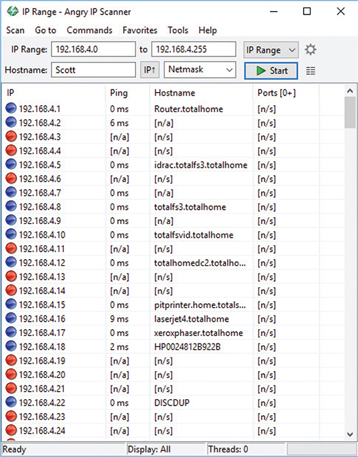
Figure 21-7 Angry IP Scanner
EXAM TIP Sometimes a GUI tool like Wireshark won’t work because a server has no GUI installed. In situations like this, tcpdump is the go-to choice. This great command-line tool not only enables you to monitor and filter packets in the terminal, but can also create files you can open in Wireshark for later analysis. Even better, it’s installed by default on most UNIX/Linux systems.
Throughput Testers
Throughput testers enable you to measure the data flow in a network. Which tool is appropriate depends on the type of network throughput you want to test. Most techs use one of several speed-test sites for checking an Internet connection’s throughput, such as MegaPath’s Speakeasy Speed Test (Figure 21-8): www.speakeasy.net/speedtest. The CompTIA Network+ exam objectives refer to throughput testers as bandwidth speed testers.
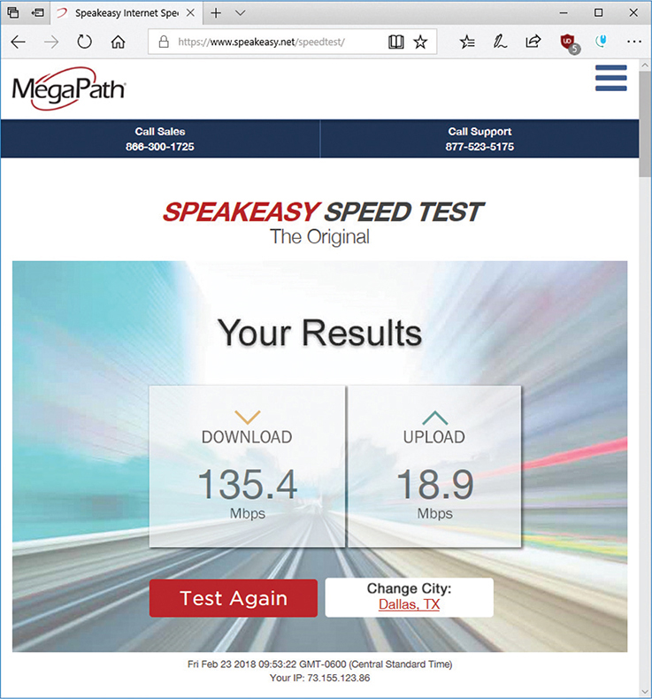
Figure 21-8 Speed Test results from Speakeasy
Looking Glass Sites
Sometimes you need to perform a ping or traceroute from a location outside of the local environment. Looking glass sites are remote servers accessible with a browser that contain common collections of diagnostic tools such as ping and traceroute, plus some Border Gateway Protocol (BGP) query tools.
Most looking glass sites allow you to select where the diagnostic process will originate from a list of locations, as well as the target destination, which diagnostic, and sometimes the version of IP to test. A Google search for “looking glass sites” or “looking glass servers” will provide a large selection from which to choose.
The Troubleshooting Process
Troubleshooting is a dynamic, fluid process that requires you to make snap judgments and act on them to try and make the network go. Any attempt to cover every possible scenario here would be futile at best, and probably also not in your best interest. If an exhaustive listing of all network problems is impossible, then how do you decide what to do and in what order?
Before you touch a single console or cable, you should remember two basic rules. For starters, to paraphrase the Hippocratic Oath, “First, do no harm.” If at all possible, don’t make a network problem bigger than it was originally. This is a rule I’ve broken thousands of times, and you will too.
But if I change the good doctor’s phrase a bit, it’s possible to formulate a rule you can actually live with: “First, do not trash the data!” My gosh, if I had a dollar for every megabyte of irreplaceable data I’ve destroyed, I’d be rich! I’ve learned my lesson, and you should learn from my mistakes.
The second rule is: “Always make good backups!” Computers can be replaced; data that is not backed up is, at best, expensive to recover and, at worst, gone forever.
No matter how complex and fancy, any troubleshooting process can be broken down into simple steps. Having a sequence of steps to follow makes the entire troubleshooting process simpler and easier, because you have a clear set of goals to achieve in a specific sequence.
The CompTIA Network+ exam objectives contain a detailed troubleshooting methodology that provides a good starting point for our discussion. Here are the basic steps in the troubleshooting process:
1. Identify the problem.
a. Gather information.
b. Question users.
c. Identify symptoms.
d. Determine if anything has changed.
e. Duplicate the problem, if possible.
f. Approach multiple problems individually.
2. Establish a theory of probable cause.
a. Question the obvious.
b. Consider multiple approaches:
i. Top-to-bottom/bottom-to-top OSI model
ii. Divide and conquer
3. Test the theory to determine the cause.
a. If the theory is confirmed, determine the next steps to resolve the problem.
b. If the theory is not confirmed, reestablish a new theory or escalate.
4. Establish a plan of action to resolve the problem and identify potential effects.
5. Implement the solution or escalate as necessary.
6. Verify full system functionality and, if applicable, implement preventive measures.
7. Document findings, actions, outcomes, and lessons learned.
Identify the Problem
First, identify the problem. That means grasping the true problem, rather than what someone tells you. A user might call in and complain that he can’t access the Internet from his workstation, for example, which could be the only problem. But the problem could also be that the entire wing of the office just went down and you’ve got a much bigger problem on your hands. You need to gather information, question users, identify symptoms, determine if anything has changed on the network, duplicate the problem (if possible), and approach multiple problems individually. Following these steps will help you get to the root of the problem.
Gather Information, Question Users, and Identify Symptoms
Gather information about the situation. If you are working directly on the affected system and not relying on somebody on the other end of a telephone to guide you, you will identify symptoms through your observation of what is (or isn’t) happening.
If you’re troubleshooting over the telephone (always a joy, in my experience), you will need to question users. These questions can be close-ended, which is to say there can only be a yes-or-no-type answer, such as, “Can you see a light on the front of the monitor?” You can also ask open-ended questions, such as, “What have you already tried in attempting to fix the problem?”
The type of question you ask at any given moment depends on what information you need and on the user’s knowledge level. If, for example, the user seems to be technically oriented, you will probably be able to ask more close-ended questions because they will know what you are talking about. If, on the other hand, the user seems to be confused about what’s happening, open-ended questions will allow him or her to explain in his or her own words what is going on.
Determine If Anything Has Changed
Determine if anything has changed on the network recently that might have caused the problem. You may not have to ask many questions before the person using the problem system can tell you what has changed, but, in some cases, establishing if anything has changed can take quite a bit of time and involve further work behind the scenes. Here are some examples of questions to ask:
• “What exactly was happening when the problem occurred?”
• “Has anything been changed on the system recently?”
• “Has the system been moved recently?”
Notice the way I’ve tactfully avoided the word you, as in “Have you changed anything on the system recently?” This is a deliberate tactic to avoid any implied blame on the part of the user. Being nice never hurts, and it makes the whole troubleshooting process more friendly.
You should also internally ask yourself some isolating questions, such as “Was that machine involved in the software push last night?” or “Didn’t a tech visit that machine this morning?” Note you will only be able to answer these questions if your documentation is up to date. Sometimes, isolating a problem may require you to check system and hardware logs (such as those stored by some routers and other network devices), so make sure you know how to do this.
EXAM TIP Avoid aggressive or accusatory questions when trying to get information from a user.
Duplicate the Problem
One of the first steps in trying to determine the cause of a problem is to understand the extent of the problem. Is it specific to one user or is it network-wide? Sometimes this entails trying the task yourself, both from the user’s machine and from your own or another machine.
For example, if a user is experiencing problems logging into the network, you might need to go to that user’s machine and try to use his or her username to log in. In other words, try to duplicate the problem. Doing this tells you whether the problem is a user error of some kind, as well as enables you to see the symptoms of the problem yourself. Next, you probably want to try logging in with your own username from that machine, or have the user try to log in from another machine.
In some cases, you can ask other users in the area if they are experiencing the same problem to see if the issue is affecting more than one user. Depending on the size of your network, you should find out whether the problem is occurring in only one part of your company or across the entire network.
What does all of this tell you? Essentially, it tells you how big the problem is. If nobody in an entire remote office can log in, you may be able to assume that the problem is the network link or router connecting that office to the server. If nobody in any office can log in, you may be able to assume the server is down or not accepting logins. If only that one user in that one location can’t log in, the problem may be with that user, that machine, or that user’s account.
EXAM TIP Eliminating variables is one of the first tools in your arsenal of diagnostic techniques.
Approach Multiple Problems Individually
If you encounter a complicated scenario, with various machines off the network and potential server room or wiring problems, break it down. Approach multiple problems individually to sort out root causes. Methodically tackle them and you’ll eventually have a list of one or more problems identified. Then you can move on to the next step.
Establish a Theory of Probable Cause
Once you’ve identified one or more problems, try to figure out what could have happened. In other words, establish a theory of probable cause. Just keep in mind that a theory is not a fact. You might need to chuck the theory out the window later in the process and establish a revised theory.
This step comes down to experience—or good use of the support tools at your disposal, such as your knowledge base. You need to select the most probable cause from all the possible causes, so the solution you choose fixes the problem the first time. This may not always happen, but whenever possible, you want to avoid spending a whole day stabbing in the dark while the problem snores softly to itself in some cozy, neglected corner of your network.
Don’t forget to question the obvious. If Bob can’t print to the networked printer, for example, check to see that the printer is plugged in and turned on.
Consider multiple approaches when tackling problems. This will keep you from locking your imagination into a single train of thought. You can use the OSI seven-layer model as a troubleshooting tool in several ways to help with this process. Here’s a scenario to work through.
Martha can’t access the database server to start her workday. The problem manifests this way: She opens the database client on her computer, then clicks on recent documents, one of which is the current project that management has assigned to her team. Nothing happens. Normally, the database client connects to the database that resides on the server on the other side of the network.
Try a top-to-bottom or bottom-to-top OSI model approach to the problem. Sometimes it pays to try both. Here are some ideas on how this might help.
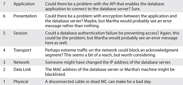
You might imagine the reverse model in some situations. If the network was newly installed, for example, running through some of the basic connectivity at Layers 1 and 2 might be a good first approach.
Another option for tackling multiple options is to use the divide and conquer approach.
On its face, divide and conquer appears to be a compromise between top-to-bottom OSI troubleshooting and bottom-to-top OSI troubleshooting. But it’s better than a compromise. If we arbitrarily always perform top-to-bottom troubleshooting, we’ll waste a lot of time at Layers 7 through 3 to troubleshoot Data Link layer and Physical layer issues.
Divide and conquer is a time saver that comes into play as part of developing a theory of probable cause. As you gather information for troubleshooting, a general sense of where the problem lies should manifest. Place this likely cause at the appropriate layer of the OSI model and begin to test the theory and related theories at that layer. If the theory bears out, follow the appropriate troubleshooting steps. If the theory is wrong, move up or down the OSI model with new theories of probable causes.
Test the Theory to Determine the Cause
With the third step, you need to test the theory to determine the cause, but do so without changing anything or risking any repercussions. If you have determined that the probable cause for Bob not being able to print is that the printer is turned off, go look. If that’s the case, then you should plan out your next step to resolve the problem. Do not act yet! That comes next.
If the theory is not confirmed, you need to reestablish a new theory or escalate the problem. Go back to step two and determine a new probable cause. Once you have another idea, test it.
The reason you should hesitate to act at this third step is that you might not have permission to make the fix or the fix might cause repercussions you don’t fully understand yet. For example, if you walk over to the print server room to see if the printer is powered up and online and find the door padlocked, that’s a whole different level of problem. Sure, the printer is turned off, but management has done it for a reason. In this sort of situation, you need to escalate the problem.
To escalate has two meanings: either to inform other parties about a problem for guidance or to pass the job off to another authority who has control over the device/issue that’s most probably causing the problem. Let’s say you have a server with a bad NIC. This server is used heavily by the accounting department, and taking it down may cause problems you don’t even know about. You need to inform the accounting manager to consult about what to do next. Alternatively, you’ll come across problems over which you have no control or authority. A badly acting server across the country is the responsibility of another person (hopefully) to whom you need to hand over the job.
Regardless of how many times you need to go through this process, you’ll eventually reach a theory that seems right. If the theory is confirmed, determine the next steps you need to take to resolve the problem.
Establish a Plan of Action and Identify Potential Effects
By this point, you should have some ideas as to what the problem might be. It’s time to “look before you leap” and establish a plan of action to resolve the problem. An action plan defines how you are going to fix this problem. Most problems are simple, but if the problem is complex, you need to write down the steps. As you do this, think about what else might happen as you go about the repair. Identify the potential effects of the actions you’re about to take, especially the unintended ones. If you take out a switch without a replacement switch at hand, the users might experience excessive downtime while you hunt for a new switch and move them over. If you replace a router, can you restore all the old router’s settings to the new one or will you have to rebuild from scratch?
Implement the Solution or Escalate as Necessary
Once you think you have isolated the cause of the problem, you should decide what you think is the best way to fix it and then implement the solution, whether that’s giving advice over the phone to a user, installing a replacement part, or adding a software patch. Or, if the solution you propose requires either more skill than you possess at the moment or falls into someone else’s purview, escalate as necessary to get the fix implemented.
If you’re the implementer, follow these guidelines. All the way through implementation, try only one likely solution at a time. There’s no point in installing several patches at once, because then you can’t tell which one fixed the problem. Similarly, there’s no point in replacing several items of hardware (such as a hard disk and its controller cable) at the same time, because then you can’t tell which part (or parts) was faulty.
As you try each possibility, always document what you do and what results you get. This isn’t just for a future problem either—during a lengthy troubleshooting process, it’s easy to forget exactly what you tried two hours before or which thing you tried produced a particular result. Although being methodical may take longer, it will save time the next time—and it may enable you to pinpoint what needs to be done to stop the problem from recurring at all, thereby reducing future call volume to your support team—and as any support person will tell you, that’s definitely worth the effort!
Then you need to test the solution. This is the part everybody hates. Once you think you’ve fixed a problem, you should try to make it happen again. If you can’t, great! But sometimes you will be able to re-create the problem, and then you know you haven’t finished the job at hand. Many techs want to slide away quietly as soon as everything seems to be fine, but trust me on this, it won’t impress your customer when her problem flares up again 30 seconds after you’ve left the building—not to mention that you get the joy of another two-hour car trip the next day to fix the same problem, for an even more unhappy client!
In the scenario where you are providing support to someone else rather than working directly on the problem, you should have her try to re-create the problem. This tells you whether she understands what you have been telling her and educates her at the same time, lessening the chance that she’ll call you back later and ask, “Can we just go through that one more time?”
EXAM TIP Always test a solution before you walk away from the job!
Verify Full System Functionality and Implement Preventive Measures
Okay, now that you have changed something on the system in the process of solving one problem, you must think about the wider repercussions of what you have done. If you’ve replaced a faulty NIC in a server, for instance, will the fact that the MAC address has changed (remember, it’s built into the NIC) affect anything else, such as the logon security controls or your network management and inventory software? If you’ve installed a patch on a client PC, will this change the default protocol or any other default settings that may affect other functionality? If you’ve changed a user’s security settings, will this affect his or her ability to access other network resources? This is part of testing your solution to make sure it works properly, but it also makes you think about the impact of your work on the system as a whole.
Make sure you verify full system functionality. If you think you’ve fixed the problem between Martha’s workstation and the database server, have her open the database while you’re still there. That way you don’t have to make a second tech call to resolve an outstanding issue. This saves time and money and helps your customer do his or her job better. Everybody wins.
Also at this time, if applicable, implement preventive measures to avoid a repeat of the problem. If that means you need to educate the user to do or not do something, teach him or her tactfully. If you need to install software or patch a system, do it now.
Document Findings, Actions, Outcomes, and Lessons Learned
It is vital that you document findings, actions, outcomes, and lessons learned of all support calls, for two reasons: First, you’re creating a support database to serve as a knowledge base for future reference, enabling everyone on the support team to identify new problems as they arise and know how to deal with them quickly, without having to duplicate someone else’s research efforts. Second, documentation enables you to track problem trends and anticipate future workloads, or even to identify a particular brand or model of an item, such as a printer or a NIC, that seems to be less reliable or that creates more work for you than others. Don’t skip this step—it really is essential!
EXAM TIP Memorize these problem analysis steps:
1. Identify the problem.
a. Gather information.
b. Question users.
c. Identify symptoms.
d. Determine if anything has changed.
e. Duplicate the problem, if possible.
f. Approach multiple problems individually.
2. Establish a theory of probable cause.
a. Question the obvious.
b. Consider multiple approaches:
i. Top-to-bottom/bottom-to-top OSI model
ii. Divide and conquer
3. Test the theory to determine the cause.
a. If the theory is confirmed, determine the next steps to resolve the problem.
b. If the theory is not confirmed, reestablish a new theory or escalate.
4. Establish a plan of action to resolve the problem and identify potential effects.
5. Implement the solution or escalate as necessary.
6. Verify full system functionality and, if applicable, implement preventive measures.
7. Document findings, actions, outcomes, and lessons learned.
Resolving Common Network Service Issues
Network problems fall into several basic categories, and most of these problems you or a network tech in the proper place can fix. Fixing problems at the workstation, work area, or server is a network tech’s bread and butter. The same is true of other nearby problems such as connecting to local resources. Problems connecting to far-flung resources can also often be resolved at the local level, but sometimes you’ll need to escalate them. Finally, network performance issues can require patient detective work to locate the trouble. The knowledge from the previous chapters combined with the tools and methods you’ve learned in this chapter should enable you to fix just about any network!
There are a couple of stumbling blocks when it comes to resolving network issues. First, at almost any level of problem, the result—as far as the end user is concerned—is the same. He or she can’t access resources beyond the local machine. Whether a user tries to access the local file server or do a Google search, if the attempt fails, “the network is down!” You need to fall back on the most important question a tech can ask: What can cause this problem? Then methodically work through the troubleshooting steps and tools to narrow possibilities. Let’s look at a scenario to illustrate the narrowing process.
“We Can’t Access Our Web Server in Istanbul!”
Everyone in the local office appears to have full access to local and Internet Web sites. No one, however, can reach a company-operated server at a particular remote site in Istanbul. There has been a recent change to the firewall configuration, so it is up to a technician, Terry, to determine if the firewall change is the culprit or if the problem lies elsewhere.
Terry has come up with three possible theories: the remote server is down, the remote site is inaccessible, or the local firewall is preventing communication with the server. He elects to test his theories with the “quickest to test” approach. His first test is to confirm that all of the local office workstations cannot reach the remote server. Using different hosts, he uses the ping and ping6 utilities. First, he pings localhost to confirm the workstation has a working IP stack, then he attempts to ping the remote server and gets no response. Next, he tries the tracert and traceroute utilities on the different hosts. Traceroute shows a functional path to the router that connects the remote office to the Internet but does not get a response from the server.
So far, everything seems to confirm that the local office cannot get to the remote server. Just to be able to say he tried everything, Terry runs the mtr utility from a Linux box and lets it run for an extended time. At the same time, he runs the pathping utility from a Windows computer. Neither utility can contact the server. He tries all of these utilities on some other company resources and Internet sites and has no problems connecting.
Confident that the reported symptom is confirmed, Terry puts in a call to the remote site to ask about the status. The virtual PBX sends Terry to voicemail for every extension that he calls. This could point to a network disconnection at the site or to everyone being out of the office there. Since it is 3:00 a.m. at the remote site, Terry does not have a clear answer.
The next quick test to perform is to see if the site is reachable from outside of the local office. This will confirm or eliminate his theory of a local incorrect host-based firewall settings issue.
Terry sits down at a computer and searches on Google for a looking glass site. He selects one from the results list and browses to the site. Once in the site, he selects the location of a source router to perform a diagnostic test, and then he selects the type of test to run; in this case, he chooses a ping test. He enters the target server address of the company’s remote server and submits the test parameters. After a moment, the looking glass server sends a set of pings, none of which receives a response. He tries the test from a few other source router locations and gets the same results.
To complete his tests, Terry uses the looking glass site to ping some additional hosts at the remote site and is pleased to discover that they are all reachable. Now Terry knows that the site is accessible, so it must be that the server is down. When the office opens, he will contact the technician there and offer whatever help and information that he can. In the meantime, he informs the rest of the organization of the server’s status.
Narrowing the problem to a single source—an apparently down server—doesn’t get all the way to the bottom of the problem (although it certainly helps!). What could cause an unresponsive server?
• Local power outage, like a blown circuit breaker
• Failed NIC on the server
• Network cable disconnected
• Improper network configuration on the server
• A changed patch cable location in the rack
• Failed component in the server
• Server shutdown
• A whole lot of other possibilities
Let’s look at some network troubleshooting considerations to keep in mind, and then review a number of specific problems from a hands-on view, then expand our view to nearby problems, expand it further to consider far-flung issues, and finish with performance issues that could crop up anywhere.
Network Troubleshooting Considerations
Any time trouble pops up with our networks, it can be easy to get pulled right into the details of the first user report, pick a thread, start pulling on it, and see where it takes you. Sometimes this is exactly what you’ll have to do to track down the source of a problem—but occasionally you can end up having trouble seeing the forest for the trees. The CompTIA Network+ objectives specifically call out a small number of considerations to keep in mind as you troubleshoot so that you’ll notice cases where they might help you narrow down possibilities or find the problem faster.
Device Configuration Review
Whenever you run into network trouble, it’s a good idea to consider the possibility that someone (or maybe even just an update) has changed a device configuration recently. This might’ve been a documented change, or maybe someone else was trying to troubleshoot a different problem and forgot to revert or document the change. If a user had sufficient permissions on the system, they may have fiddled with settings themselves to try and get things working again.
There’s a risk here that someone trying to fix a problem has changed the settings to something that won’t work no matter what you do. Especially with user devices, make sure they are configured correctly before you start looking at the network itself.
Most managed network devices, such as a switch or a router, enable you to get to a terminal—such as through SSH—and type commands to show the current configuration of the device. The information would include the users and hostname, configured protocols such as Spanning Tree Protocol or BGP, and configuration of individual interfaces (such as trunking, VLAN assignment, and more).
The specific commands for show config—the overall category of commands—differ among the many operating systems used on these devices. A tech might ask, “Did you run a show config on that router?” and the specific command would vary from device to device.
Interface Status
While it seems simple enough, checking the interface status of the systems involved can help resolve many networking issues quickly. So instead of looking first for a more complex cause to your problem, don’t forget to consider the interface status of the devices you’re troubleshooting.
The shorthand command to display the current interface status from a terminal is show interface. IOS and Junos OS lengthen the precise command to show interfaces, which you saw back in Chapter 11. On physical devices, the command would show the status of a specific port, such as type of hardware, MAC address, description, media type, number of packets, and more.
Routing Tables
If you are troubleshooting a Layer 3 problem, consider the routing tables of the various routers, firewalls, and other devices that the packets are moving through. Checking the routing tables directly enables you to see how the packets will be forwarded through the network. This can help point to a direct problem with the routes themselves or indicate that the packets are taking a path through the network you didn’t know about.
The shorthand command to display routing table information at a terminal is show route, though the specific commands vary by OS. Junos OS uses show route. A common version of IOS uses show ip route. Regardless, the information displayed is the same, the routing tables for that device. The command shows where the router thinks a packet should go.
EXAM TIP The CompTIA Network+ objectives place show interface, show config, and show route under the subobjective “Basic network platform commands.” That would make the casual reader think these were specific commands. Although some operating systems might use the specific language, all of them vary to some degree. It’s best to think about the three terms as shorthand or categories of commands.
VLAN Assignment
Like the other considerations just described, doing a quick review of the VLAN assignments is good practice when troubleshooting. You could be dealing with a simple incorrect port assignment, or more complex problems. While this will be most important when troubleshooting Layer 2 issues, VLAN assignment also plays a role in problems further up the OSI stack.
Network Performance Baselines
One of the best things you can do to keep a network in good shape is to invest time now to set up performance monitoring via a network monitoring system (NMS) or take periodic benchmarks and learn what kind of performance and access patterns are normal when all is well. When your future self is unsettled by a few vague complaints about speed or reliability, having access to historical network performance baselines can be the difference between knowing where to look and having to let the problem fester until you have enough user reports to connect the dots. The baselines may even help you proactively spot failing or misconfigured devices, catch compromised hosts up to no good, or plan for extra capacity before performance falls off a cliff.
Hands-On Problems
Hands-on problems refer to things that you can fix at the workstation, work area, or server. These include physical problems and configuration problems.
A power failure or power anomalies, such as dips and surges, can make a network device unreachable. We’ve addressed the fixes for such issues a couple of times already in this book: manage the power to the network device in question and install an uninterruptible power supply (UPS).
A hardware failure can certainly make a network device unreachable. Fall back on your CompTIA A+ training for troubleshooting. Check the link lights on the NIC. Try another NIC if the machine seems functional in every other aspect. Ping the localhost.
Pay attention to link lights when you have a “hardware failure.” The network connection light-emitting diode (LED) status indicators—link lights—can quickly point to a connectivity issue. Try known-good cables/NICs if you run into this issue.
Hot-swappable transceivers (which you read about way back in Chapter 4) can go bad. The key when working with small form-factor pluggable (SFP) or the much older gigabit interface converter (GBIC) transceivers is that you need to check both the media and the module. In other words, a seemingly bad SFP/GBIC could be the cable connected to it or the transceiver. As with other hardware issues, try known-good components to troubleshoot.
Outside invisible forces can cause problems with copper cabling. You’ve read about electromagnetic interference (EMI) and radio frequency interference (RFI) previously in the book. EMI and RFI can disrupt signaling on a copper cable, especially with the very low voltages used today on those cables. These are crazy things to troubleshoot.
An interference problem might manifest in a scenario like this one. John can use e-mail on his laptop successfully over the company’s wireless network. When he plugs in at his desk in his cubicle, however, e-mail messages just don’t get through.
Typically, you’d test everything before suspecting EMI or RFI causing this problem. Test the NIC on the laptop by plugging into a known-good port. You’d use a cable tester on the cable. You’d check for continuity between the port in John’s office to the switch. You’d glance at the cabling certification documents to see that, yes, the cable worked when installed.
Only then might a creative tech at her wit’s end notice the recently installed, high-powered WAP on the wall outside Tom’s office across from John’s cubicle. RFI strikes!
If the installation is new and unproven, a perfectly fine network device might be unreachable because of interface errors, meaning that the installer didn’t install the wall jack correctly. The resulting incorrect termination might be a mismatched standard (568A rather than 568B, for example). The cable from the wall to the workstation might be bad or might be a crossover cable rather than straight-through cable. That’s an incorrect cable type, according to the CompTIA Network+ objectives. Try another cable.
Aside from obvious physical problems, other hands-on problems you can fix manifest as some sort of misconfiguration. IP setting issues, such as setting a PC to an incorrect IP address that’s not on the same network ID as other resources, would result in a “dead-to-me” network. A similar fate would result from inputting incorrect gateway IP address information. The same is true with an incorrect subnet mask setting—that is, the subnet mask isn’t accurate. If it has an incorrect DNS server address, the system might have trouble resolving all DNS names. (This may be more subtle, such as only internal DNS names failing, if the address is a valid DNS server—just not the right one.) The system will go nowhere, fast.
The fix for these sorts of problems should be pretty obvious to you at this point. Go into the network configuration for the device and put in correct numbers. Figure 21-9 shows TCP/IP settings for a Windows Server machine.
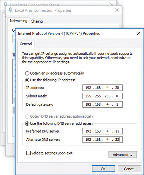
Figure 21-9 TCP/IP settings in Windows Server
Some problems that you can fix at the local machine don’t point to messed-up hardware or invalid settings, but reflect the current mix of wired and wireless networks in the same place. Here’s a scenario that applies to Windows versions before Windows 10. Tina has a wireless network connection to the Internet. She gets a shiny new printer with an Ethernet port, but with no Wi-Fi capability. She wants to print from both her PC and her laptop, so she creates a small LAN: a couple of Ethernet cables and a switch. She plugs everything in, installs drivers, and all is well. She can print from both machines. Unfortunately, as soon as she prints, her Internet connection goes down.
The funny part is that the Internet connection didn’t go anywhere, but her simultaneous wired/wireless connections created a network failure. The wired and wireless NICs can’t actually operate simultaneously and, by default, the wired connection takes priority in the order in which devices are accessed by network services.
To fix this problem, open Network Connections in the Control Panel. Press the ALT key to activate the menu bar, then select Advanced | Advanced Settings (Figure 21-10). Change the connection priority in the Advanced Settings options by selecting the one Tina wants to take priority and clicking the up arrow to move it up the list.
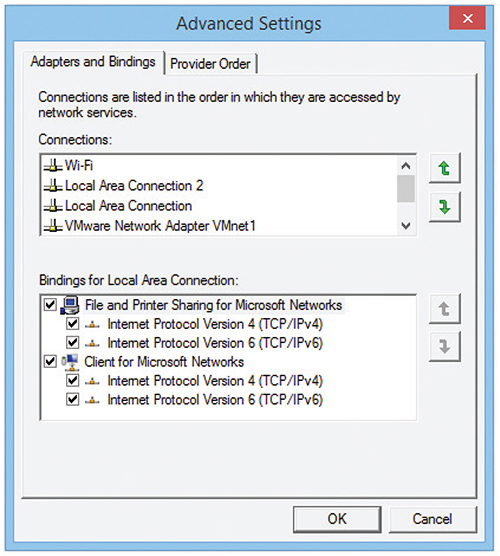
Figure 21-10 Network Connections Advanced Settings
EXAM TIP Windows 10 does not have this simultaneous wired/wireless connection issue at all, so the problem is irrelevant as long as your clients have updated computers. You might see this issue in an exam question, though hopefully CompTIA has let it go.
Nearby Problems
Incorrect configuration of any number of options in devices can stop a device from accessing nearby resources. These problems can be simple to fix, although tracking down the culprit can take time and patience.
One of the most obvious errors occurs when you’re duplicating machines and using static IP addresses. As soon as you plug in the duplicated machine with its duplicate IP address, the network will howl. No two computers can have the same IP address on a broadcast domain. The fix for the problem is to change the IP address on the new machine either to an unused static IP address or to DHCP.
A related issue comes from duplicate MAC addresses, something that can happen when working with virtual machines or, rarely, as a result of a manufacturing error. The effect is the same as duplicate IP addresses. Either put the devices on different VLANs or swap out NICs to avoid duplication.
An expired IP address can cause a system not to connect. Release/renew to obtain a proper IP address from the DHCP server. If the DHCP server’s scope of IP addresses has been claimed, that release/renew won’t work. You’ll get an error that points to DHCP scope exhaustion. The only fix for this is to make changes at the DHCP server.
NOTE A DHCP starvation attack, like you read about in Chapter 19, causes DHCP scope exhaustion.
Client Misconfigurations
Most clients use DHCP for IP address, subnet mask, and default gateway settings. With manual configuration, on the other hand, errors can creep in and cause a device to fail to connect to network resources. A typical scenario is with a bring your own device (BYOD) environment, where an employee brings in a manually configured laptop—forgetting that it’s tuned to his home network—and complains about not being able to access the LAN or the Internet.
Anything that doesn’t match the LAN settings will cause a client to fail to connect. An IP address that doesn’t match the subnet, for example, will bring no love. An error in the subnet mask settings will stop client access cold. A DNS server setting that’s not accurate can cause name resolution failure. If the default gateway address is incorrect—an incorrect gateway issue—then there’s no Internet for the client.
Server Misconfigurations
Misconfigurations of server settings can block all or some access to resources on a LAN. Misconfigured DHCP settings on a host above can cause problems, but they will be limited to the host. If these settings are misconfigured on the DHCP server, however, many more machines and people can be affected. A misconfigured DNS server might direct hosts to incorrect sites or no sites at all. It might appear as an unresponsive service and just do nothing. Misconfigured DNS settings on a client results in names not resolving and causes the network to appear to be down for the user.
You’ll be clued into such misconfiguration by using ping and other tools. If you can ping a file server by IP address but not by name, this points to DNS issues. Similarly, if a computer fails in discovering neighboring devices/nodes, like connecting to a networked printer, DHCP or DNS misconfiguration can be the culprit. To fix the issue, go into the network configuration for the client or the server and find the misconfigured settings.
Adding VLANs
When you add VLANs into the network mix, all sorts of fun network issues can crop up. As an example, suppose Bill has a 24-port managed switch segmented into four VLANs, one for each group in the office: Management, Sales, Marketing, and Development (Figure 21-11).
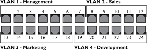
Figure 21-11 Bill’s VLAN assignments
Bill thought he’d assigned six ports to each VLAN when he set up the switch, but by mistake he assigned seven ports to VLAN 1 and only five ports to VLAN 2. Merrily plugging in the patch cables for each group of users, Bill gets called up by his boss asking why Cindy over in Sales suddenly can see resources reserved for Management. This obviously points to an interface misconfiguration that resulted in a VLAN mismatch, a lovely phrase meaning Bill put somebody into the incorrect VLAN.
Similarly, after fixing his initial mistake and getting the VLANs set up properly, Bill needs to plug the right patch cables into the right ports. If he messes up and plugs the patch cable for Cindy’s computer into a VLAN 1 port, the intrepid salesperson would again have access to the Management resources. Such cable placement errors show up pretty quickly and are readily fixed. Keep proper records of patch cable assignments and plug the cables into the proper ports.
Link Aggregation Problems
Ethernet networks (traditionally) don’t scale easily. If you have a Gigabit Ethernet connection between the main switch and a very busy file server, that connection by definition can handle up to 1-Gbps bandwidth. If that connection becomes saturated, the only way to bump up the bandwidth cap on that single connection would be to upgrade both the switch and the server NIC to the next higher Ethernet standard, 10-Gigabit Ethernet. That’s a big jump and an expensive one, plus it’s an upgrade of 1000 percent! What if you needed to bump up bandwidth by only 20 percent?
The scaling issue became obvious early on, so manufacturers came up with ways to use multiple NICs in tandem to increase bandwidth in smaller increments, what’s called link aggregation or NIC teaming, which you’ll recall from way back in Chapter 11. Numerous protocols enable two or more connections to work together simultaneously, such as the vendor-neutral IEEE 802.1AX-2020 specification Link Aggregation Control Protocol (LACP) and the Cisco-proprietary Port Aggregation Protocol (PAgP). Let’s focus on the former for a common network issue scenario.
To enable LACP between two devices, such as the switch and file server just noted, each device needs two or more interconnected network interfaces configured for LACP. When the two devices interact, they will make sure they can communicate over multiple physical ports at the same speeds and form a single logical port that takes advantage of the full combined bandwidth (Figure 21-12).
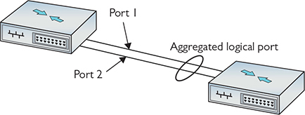
Figure 21-12 LACP
Those ports can be in one of two modes: active or passive. Active ports want to use LACP and send special frames out trying to initiate creating an aggregated logical port. Passive ports wait for active ports to initiate the conversation before they will respond.
So here’s the common network error with LACP setups. An aggregated connection set to active on both ends (active-active) automatically talks, negotiates, and works. A connection set to active on one end and passive on the other (active-passive) talks, negotiates, and works. But if you set both ends to passive (passive-passive), neither will initiate the conversation and LACP will not engage. Setting both ends to passive when you want to use LACP is an example of NIC teaming misconfiguration.
NIC teaming provides many more benefits than just increasing bandwidth, such as redundancy. You can team two NICs in a logical unit but set them up with one NIC as the primary—live—and the second as the hot spare—standby. If the first NIC goes down, the traffic will automatically flow through the second NIC. In a simple network set up for redundancy, you’d make one connection live and the other as standby on each device. Switch A has a live and a standby, Switch B has a live and a standby, and so on.
The key here is that multicast traffic to the various devices needs to be enabled on every device through which that traffic might pass. If Switch C doesn’t play nice with multicast and it’s connected to Switch B, this can cause multicast traffic to stop. One “fix” for this in a Cisco network is to turn off a feature called IGMP snooping, which is enabled by default on Cisco switches. IGMP snooping is normally a good thing, because it helps the switches keep track of devices that use multicast and filter traffic away from devices that don’t.
The problem with turning off IGMP snooping is that the switches won’t map and filter multicast traffic. Instead of only sending to the devices that are set up to receive multicast, the switches will treat multicast messages as broadcast messages and send them to everybody. This is a NIC teaming misconfiguration that can seriously degrade network performance.
A better fix would be to send a couple of network techs to change settings on Switch C and make it send multicast packets properly.
Broadcast Storms
A broadcast storm is the result of one or more devices sending a nonstop flurry of broadcast frames on the network. The first sign of a broadcast storm is when every computer on the broadcast domain suddenly can’t connect to the rest of the network. There are usually no clues other than network applications freezing or presenting “can’t connect to…” types of error messages. Every activity light on every node is solidly on. Computers on other broadcast domains work perfectly well.
The trick is to isolate; that’s where escalation comes in. You need to break down the network quickly by unplugging devices until you can find the one causing trouble. Getting a packet analyzer to work can be difficult, but you should at least try. If you can scoop up one packet, you’ll know what node is causing the trouble. The second the bad node is disconnected, the network returns to normal. But if you have a lot of machines to deal with and a bunch of users who can’t get on the network yelling at you, you’ll need help. Call a supervisor to get support to solve the crisis as quickly as possible.
Switching Loops
Also known as a bridging loop, a switching loop is when you connect and configure multiple switches together in such a way that causes a circular path to appear. Switching loops are rare because switches use the Spanning Tree Protocol (STP), but they do happen. The symptoms are identical to a broadcast storm: every computer on the broadcast domain can no longer access the network.
The good part about switching loops is that they rarely take place on a well-running network. Someone had to break something, and that means someone, somewhere is messing with the switch configuration. Escalate the problem, and get the team to help you find the person making changes to the switches.
Multicast Flooding
Related to broadcast storms, though not as destructive, is multicast flooding. Multicast is a Layer 3 technology and, therefore, switches see multicast traffic as broadcasts that they dutifully forward to every port in the broadcast domain. Multicast flooding is not much of an issue when you’re dealing with something like phone intercoms, but it becomes much more of a problem if you are using multicast for things like high-bandwidth video. In that case, you can easily send hundreds of megabits of traffic to every host on the LAN.
To mitigate problems with multicast flooding, you can move all the systems that need to participate in the multicast group to their own VLAN or physically separate network. This will minimize the flooding to hosts on that broadcast domain. But do note that this still can saturate any trunks line that carry that VLAN’s traffic.
Another approach to mitigating multicast issues is to enable IGMP snooping on your switches. This will let your switches forward multicast traffic only to ports with hosts that are members of a multicast group. IGMP snooping works by letting the switch “listen” for when the host joins a multicast group, and only then will the switch forward frames from that multicast to that host.
Time Issues
Most devices these days rely on the NIST time servers on the Internet to regulate time. Every once in a while (like on the CompTIA Network+ exam), you’ll see a scenario where machines, isolated from the Internet (and thus removed from a time server and the ubiquitous Network Time Protocol, or NTP), will get out of sync. This can result in incorrect time issues that stop services from working properly. Did I mention that this is rare? The CompTIA Network+ objectives call this NTP issues.
Collisions
While collisions—two devices trying to speak on the same wire at the same time—once plagued wired networks, this problem is almost entirely behind us on modern networks. There is still at least one kind of misconfiguration—in theory and on a CompTIA exam in your near future—that can cause collisions.
If the port on one end of a connection is explicitly set to use a specific bandwidth and duplex setting, it will no longer auto-negotiate settings with its partner port at the other end. While newer high-speed Ethernet standards only support or default to full-duplex connections, older/slower standards default to half-duplex connections. When one side is set to use something like 10BASE-T at full duplex, its partner will fall back to 10BaseT at half duplex—and collisions can result because of this duplexing issue.
Because collisions have become so rare, we don’t have as many tools to diagnose them when they do crop up. But, if you do have a port that has fallen back to half-duplex mode, creating the potential for collisions, you can configure your network monitoring software to notify you. Once you know where the problem device is, you can then use the troubleshooting steps to try and determine why it is no longer auto-negotiating.
Low Optical Link Budget
For those coming from UTP cable land, installing and troubleshooting fiber adds a few wrinkles that we don’t have to worry about with copper. One of those wrinkles is your optical link budget, which is the difference between the maximum power a transceiver can transmit and the minimum power it needs to receive a signal. This budget, basically, is how much the signal can attenuate before you run into trouble.
Attenuation is affected by factors such as the number and type of connectors, cable length and quality, and how many times the cable is spliced or patched. Assuming your network was properly designed and installed, you should not run into optical link budget issues. Otherwise, these issues might accumulate until eventually the light is too dim for the receiver on the other end to cleanly detect the signal, at which point it may start having frame errors or completely lose connectivity.
If you suspect a problem, a good place to start is with the diagnostics built into more advanced switches. These diagnostics will tell you about the module’s minimum, maximum, and current transmit/receive power. If you have a network monitoring system set up, it should trigger an alarm if any of these thresholds are exceeded. Here is the diagnostics output from my Juniper switch:
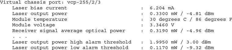
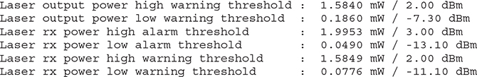
Beyond what is built into the switch, you’ll want to turn to dedicated hardware diagnostic devices such as optical power meters and fiber inspectors. These tools can be used by technicians to help hunt down the source of any attenuation issues in the fiber run.
Licensed Feature Issues
I want to let you in on a little industry secret: once you move beyond SOHO gear, many of the features on network devices require specific licenses. For example, my office’s Juniper switches require a separate license to use Open Shortest Path First (OSPF) routing.
Licensing is important to keep in mind when you are purchasing new equipment or want to start using additional features your exiting gear supports. There is no technical fix for licensed feature issues—you just need to make sure you have bought (or have an active subscription for) the correct license to enable the features you need and have registered those licenses on the devices.
Far-flung Problems
Problems that stop users from accessing resources over longer distances such as across a WAN like the Internet—or even a large LAN—can originate at the local machine, the remote machine, and in switches and routers along the way. As you might infer from the opening scenario, some of these common network problems you can fix, and some you cannot. We discussed many remote connectivity problems and solutions way back in Chapter 13, so I won’t rehash them here.
This section starts with router configuration issues, problems with misconfigured multilayer network appliances, issues with certificates, and company security policies. The following section goes into bigger problems that require escalation.
Router Problems
Routers enable networks to connect to other networks, which you know well by now. Problems with routers simply make those connections not work. (Recall that physical problems with routers or router interface modules were covered in Chapter 7 and Chapter 13.) Loss of power or a bad module can certainly wreck a tech’s day, but the fixes are pretty simple: provide power or replace the module.
Router configuration issues can be a bit trickier. The ways to mess up a router are many. You can specify the wrong routing protocol, for example, or misconfigure the right routing protocol.
An access control list (ACL) might include addresses to block that shouldn’t be blocked or allow access to network resources for nodes that shouldn’t have it. Incorrect ACL settings can lead to blocked TCP/UDP ports that shouldn’t be blocked. A misconfiguration can lead to a missing route that makes some destinations unreachable for users.
Improperly configured routers aren’t going to send packets to the proper destination. The symptoms are clear: every system that uses the misconfigured router as a default gateway is either not able to get packets out or not able to get packets in, or sometimes both. Web pages don’t come up, FTP servers suddenly disappear, and e-mail clients can’t access their servers. In these cases, you need to verify first that everything in your area of responsibility works. If that is true, then escalate the problem and find the person responsible for the router.
EXAM TIP As you’ll recall from Chapter 16, if you want to prevent downtime due to a failure on your default gateway, you should consider implementing Virtual Router Redundancy Protocol (VRRP) or, if you are a Cisco shop, Gateway Load Balancing Protocol (GLBP).
One excellent tool for determining a router problem beyond your LAN is tracert/traceroute. Run traceroute to your default gateway. (You can also use ping to check connectivity.) If that fails, you know you have a local issue and can potentially do something about it. If the traceroute comes back positive, run it to a site on the Internet. A solid connection should return something like the output shown in Figure 21-13. A failed route will return a failed response.
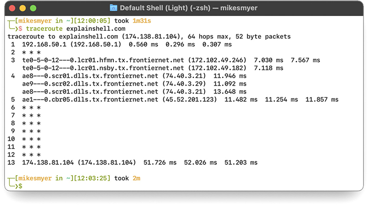
Figure 21-13 Good connection
Some extra problems show up when you zoom out and look at entire chains or webs of routers. At this scale, individual routers—and how they interact with others—shape the health of the network. At any given hop, unexpected behavior could create hard-to-troubleshoot problems. Let’s take a look at two specific cases of unexpected inter-router communication: asymmetric routing and routing loops.
Asymmetric Routing Asymmetric routing—when packets take one path to their destination but the response takes a different path back—isn’t necessarily a problem for everyone all the time, but it could still give you a headache. Some networks intentionally use asymmetric routes for performance reasons, but the different routes may confuse security and NAT devices that assume they’ll see both halves of a symmetric conversation—or mislead you about the nature of a connectivity problem that is only impacting packets sent in one direction.
Diagnosing a problem asymmetric route often involves using packet captures and traceroute to determine how the packets are actually flowing through the network. Some advanced networking devices will also detect asymmetric routes automatically and give you a heads-up about potential issues.
Routing Loops Since individual routers don’t really see the forest for the trees, they’ll happily forward a packet down a path that they think is correct but actually leads it back around to a router it has already passed through, causing a routing loop. Once this happens, the packets are doomed either to time out or to get dropped after the packet takes as many hops as its time to live (TTL) metric allows.
Routing loops are generally a misconfiguration problem between routers, and different routing protocols have different features that attempt to keep these loops from developing in the first place.
Appliance Problems
Many of the boxes that people refer to as “routers” contain many features, such as routing, Network Address Translation (NAT), switching, an intrusion detection system (IDS), a firewall, and more. These complex boxes, such as the Cisco Adaptive Security Appliance (ASA), are called network appliances.
One common issue with network appliances is technician error. By default, for example, NAT rules take precedence over an appliance’s routing table entries. If the tech fails to set the NAT rule order correctly, traffic that should be routed to go out one interface—like to the DMZ network—can go out an incorrect interface—like to the inside network.
Users on the outside would expect a response from something but instead get nothing, all because of a NAT interface misconfiguration.
The fix for such problems is to set up your network appliance correctly. Know the capabilities of the network appliance and the relationships among its services. Examine rules and settings carefully.
Certificate Issues
TLS/SSL certificates have expiration dates and companies need to maintain them properly. If you get complaints from clients that the company Web site is giving their browsers untrusted TLS/SSL certificate errors, chances are that the certificate has expired. The fix for that is pretty simple—update the certificate.
Company Security Policy
Implemented company security policies can make routine WAN connectivity actions completely fail. Here’s a scenario.
Mike is the head of his company’s IT department and he has a big problem: the amount of traffic running between the two company locations is on a dedicated connection and is blowing his bandwidth out of the water! It’s so bad that data moving between the two offices often drops to a crawl four to five times per day. Why are people using so much bandwidth?
As he inspects the problem, Mike realizes that the sales department is the culprit. Most of the data is composed of massive video files the sales department uses in their advertising campaign. He needs to make some security policy decisions. First, he needs to set up a throttling policy that defines in terms of megabits per second the maximum amount of bandwidth any single department can use per day. Second, he needs to add a blocking policy. If anyone goes over this limit, the company will block all traffic of that type for a certain amount of time (one hour). Third, he needs to update his company’s fair access policy or utilization limits security policies to reflect these new limits. This lets employees, especially those pesky sales folks, know what the new rules are.
Escalating
No single person is truly in control of an entire Internet-connected network. Large organizations split network support duties into very skill-specific areas: routers, cable infrastructure, user administration, and so on. Even in a tiny network with a single network support person, problems will arise that go beyond the tech’s skill level or that involve equipment the organization doesn’t own (usually it’s their ISP’s gear). In these situations, the tech needs to identify the problem and, instead of trying to fix it on his or her own, escalate the issue.
In network troubleshooting, problem escalation should occur when you face a problem that falls outside the scope of your skills and you need help. In large organizations, escalation problems have very clear procedures, such as who to call and what to document. In small organizations, escalation often is nothing more than a technician realizing that he or she needs help.
Network Performance Issues
Connectivity problems are great! I mean, they’re bad for users, and bad for productivity—but most of them have a clear resolution. Once someone tracks down the problem and implements a solution, we can close the ticket and move on. In contrast, network performance issues can be a bit more like stepping on abandoned chewing gum on a hot summer day.
A performance problem could just as easily be caused by a pipe that’s just too small, a router that’s running too hot, new sources of interference, ailing network devices, too many coworkers watching Netflix or Twitch while they work, poor QoS policies, backups running during your daytime peak instead of at night, an office that’s simply outgrowing its infrastructure, or a compromised host exfiltrating petabytes of your organization’s most precious data.
Network performance baselines are great to have for many kinds of troubleshooting—but they’re really great when it comes to spotting performance issues before people are cranky enough to start complaining. In all of these cases, monitoring is your friend. Monitor everything you can!
Monitor your devices and network, obviously—but don’t be shy about throwing in anything you have instruments and storage space to track. Things like temperature, humidity, the weather, indoor and outdoor air quality, the quality of electricity from your power company, the number of active Wi-Fi clients, the amount of ambient noise, and the number of active DHCP leases. Once you have all this data feeding into your NMS, make sure to set up thresholds so that you are notified when critical systems are running outside of their optimal performance range.
You won’t need most of this data most of the time. But it’s the kind of thing that can help you work your way back from complaints on Monday afternoons about Wi-Fi in the break room to the WAP on the ceiling going on the fritz when your water delivery service props the door open for 10 minutes on a muggy, sweltering Friday afternoon.
Troubleshooting Is Fun!
The art of network troubleshooting can be a fun, frolicsome, and frequently frustrating feature of your network career. By applying a good troubleshooting methodology and constantly increasing your knowledge of networks, you too can develop into a great troubleshooting artist. Developing your artistry takes time, naturally, but stick with it. Begin the training. Use the Force. Learn new stuff, document problems and fixes, and talk to other network techs about similar problems. Every bit of knowledge and experience you gain will make things that much easier for you when crunch time comes and a network disaster occurs—and as any experienced network tech can tell you, it will occur, even on the most robust network.
Chapter Review
Questions
1. When should you use a cable tester to troubleshoot a network cable?
A. When you have a host experiencing a very slow connection
B. When you have an intermittent connection problem
C. When you have a dead connection and you suspect a broken cable
D. When you are trying to find the correct cable up in the plenum
2. Why would a network technician use a tone probe and tone generator?
A. To locate a particular cable
B. To test the dial tone on a PBX system
C. To run a long-duration ping test
D. To provide safety when working in crawl spaces
3. What does nslookup do?
A. Retrieves the name space for the network
B. Queries DNS for the IP address of the supplied host name
C. Performs a reverse IP lookup
D. Lists the current running network services on localhost
4. What is Wireshark?
A. Protocol analyzer
B. Packet sniffer
C. Packet analyzer
D. All of the above
5. What will the command route print return on a Windows system?
A. The results of the last tracert
B. The gateway’s router tables
C. The routes taken by a concurrent connection
D. The current system’s route tables
6. When trying to establish symptoms over the phone, what kind of questions should you ask of a novice or confused user?
A. You should ask open-ended questions and let the user explain the problem in his or her own words.
B. You should ask detailed, close-ended questions to try and narrow down the possible causes.
C. Leading questions are your best choice for pointing the user in the right direction.
D. None; ask the user to bring the machine in because it is useless to troubleshoot over the phone.
7. While you are asking the user problem-isolating questions, what else should you be doing?
A. Asking yourself if there is anything on your side of the network that could be causing the problem
B. Nothing; just keep asking the user questions
C. Using an accusatory tone with the user
D. Playing solitaire
8. Which command shows you detailed IP information, including DNS server addresses and MAC addresses?
A. ipconfig
B. ipconfig -a
C. ipconfig /all
D. ipconfig /dns
9. What is the last step in the troubleshooting process?
A. Implementing the solution
B. Testing the solution
C. Documenting the solution
D. Closing the help ticket
10. One of your users calls you with a complaint that he can’t reach the site www.google.com. You try and access the site and discover you can’t connect either but you can ping the site with its IP address. What is the most probable culprit?
A. The workgroup switch is down.
B. Google is down.
C. The gateway is down.
D. The DNS server is down.
Answers
1. C. Cable testers can only show that you have a broken or poorly wired cable, not if the cable is up to proper specification.
2. A. Techs use tone probes and tone generators to locate individual cables.
3. B. The nslookup command queries DNS and returns the IP address of the supplied host name (and a whole lot of other details).
4. D. Wireshark can sniff and analyze all the network traffic that enters the computer’s NIC.
5. D. The route print command returns the local system’s routing tables (for IPv4 and IPv6).
6. A. With a novice or confused user, ask open-ended questions so the user can explain the problem in his or her own words.
7. A. Ask yourself if anything could have happened on your side of the network.
8. C. ipconfig /all displays detailed IP configuration information.
9. C. Documenting the solution is the last and, in many ways, the most important step in the troubleshooting process.
10. D. In this case, the DNS system is probably at fault. By pinging the site with its IP address, you have established that the site is up and your LAN and gateway are functioning properly.