This chapter covers the final block in the Common Palette. When you are finished with this chapter, you will have the ability to create some great programs for your robots and give them the ability to move, talk, listen, bump, stop, wait, and a lot more. (But there are plenty more NXT-G blocks to learn about, so don't stop reading yet!)
Let's give your robots one more talent—the ability to make choices and select from multiple possible actions. Choices are very important to your robot; with the ability to decide between two or more options, your robot can perform much more complicated actions.
Let me give SPOT some pseudo-code for his next task:
Me: SPOT, I want you to move forward three rotations and stop. If your Light sensor detects a light level over 30, turn left. Otherwise, turn right.
At this point, you already know how to program SPOT with a MOVE block that moves him forward three rotations. But how do you take the light value from the Light sensor and use it to help SPOT make a decision about turning left or right?
The answer is easy. You'll use the SWITCH block shown in Figure 12-1.

The SWITCH block uses an input value to determine a path to take. This value can be a number, a bit of text, or a Logic value (True or False). And you're not just limited to two paths. You could configure a SWITCH block to handle the following pseudo-code:
Me: SPOT, pick a random number from 1 to 5.
Me: If the number is 1, turn left.
Me: If the number is 2, turn right.
Me: If the number is 3, spin 180 degrees.
Me: If the number is 4, spin 360 degrees.
Me: If the number is 5, keep moving forward.
In this example, I have SPOT pick a random number. This is done using the RANDOM block that you'll learn about later in Chapter 14. But for now, let's just assume for the moment that SPOT can pick his own numbers. Now, since there are five potential numbers (1, 2, 3, 4, and 5), there are five potential actions that can be taken. Throughout the remainder of this chapter, I'm also going to use the term path instead of action, because the SWITCH block will allow your robots to choose from different paths available to them.
Depending on the path a robot selects, different actions will occur. One path can have your robot moving forward, checking its Ultrasonic sensor for an object in front. Selecting a different path might send the same robot in the reverse direction, waiting for its Touch sensor to be pressed and counting the number of rotations the motors spin. That's the great thing about the SWITCH block. Each potential path choice can have unique programming blocks that give your robots even more power. (And you can add another SWITCH block to a path, creating another set of paths for your robot to choose from! It's like nesting LOOP blocks but instead you're putting a new SWITCH block into an existing SWITCH block.)
Now, before I show you how the SWITCH block works, I need to mention one special item in the SWITCH block's configuration panel. Take a look at Figure 12-2.

When using the SWITCH block, you need to choose between Flat view and Tabbed view. When using Flat view, you need to leave the Flat view box checked (as shown in Figure 12-2). Flat view does have a limitation that you need to be aware of, however. When using it, you can program only two paths. Notice in Figure 12-2 that there are two paths: one labeled with a checkmark and the other with an "X". The checkmark path is also called the default path (more on this in a little bit). The icons for the default path and the other path will change, however, if a sensor is selected as the Control. I'll show an example of this shortly.
Now, in Figure 12-3 I've unchecked the Flat view box, and you can now see that the SWITCH block has tabs along the top edge.
With the Tabbed view, you must click a tab to see the programming blocks (if any) that have been placed inside it. This is a small price to pay for the ability to specify more than two options, however. Remember the earlier pseudo-code where SPOT picked a random number between 1 and 5? Figure 12-4 shows a SWITCH block with five tabs; each tab will now correspond to one of the potential actions I asked SPOT to perform.

Now it's time to show you how to configure the SWITCH block, so you can use it to give your robot choices.
In Figure 12-5, I've placed a single SWITCH block that is using the Flat view. This means I only have two possible paths for my robot to take. The first path (with the small flower icon) is on top and the second path (with the small mountain icon) is on the bottom.

This example also shows you the power of the SWITCH block. In the Control section, you have a pull-down menu that offers two options: Sensor and Value. Choosing the Sensor option will allow you to configure the SWITCH block to determine the correct path for your robot using the sensor and its trigger, which you select.
In this example, I've selected the Ultrasonic sensor. I've configured the Ultrasonic sensor to detect when an object or obstacle is detected less than 64 centimeters (but not equal to 64) in front of the robot. If this condition is met (True), the SWITCH block will execute any blocks found in the True path (the upper beam, with the small flower icon). If the condition is not met (False), the SWITCH block executes any blocks found in the False path (the lower beam, with the mountain icon).
For the moment, let's assume that SPOT has his Ultrasonic sensor and Sound sensor mounted. I'm going to give SPOT the following pseudo-code:
Me: SPOT, when your Ultrasonic sensor detects an object less than 64 centimeters in front, turn left if your Sound sensor detects a sound level greater than 20.
I've already shown you how to configure the first SWITCH block to use the Ultrasonic sensor. Let's assume that SPOT's Ultrasonic sensor detects an object less than 64 centimeters in front of him. This means that any blocks on the upper beam (True path) will be executed. From the pseudo-code, you know that if the first condition is met, you want SPOT to turn left only if his Sound sensor detects a sound greater than 20. How will you do this? Simple—you'll use another SWITCH block!
First, you drop another SWITCH block on the top beam and configure it, as shown in Figure 12-6.

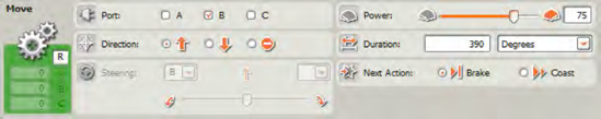
Next, configure the second SWITCH block to use the Sound sensor and to detect a sound greater than 20. If this happens, the True path (upper beam) in the second SWITCH block will execute any blocks found inside it. And that is where you'll place the MOVE block that allows SPOT to turn left (see Figure 12-7).

This is an example of embedded SWITCH blocks. You could keep going and place more SWITCH blocks inside other SWITCH blocks. This will give your robots some excellent decision-making control!
But what if you need to program your robot to test a greater number of conditions? Not all situations will have conditions that only have two options, right? Let's take another example for SPOT. Have a look at Figure 12-8.
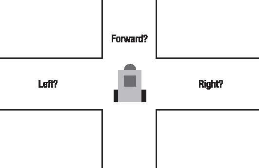
Here's the pseudo-code:
Me: SPOT, when you come to the hallway intersection, pick a number from 1 to 3. If the number is 1, turn left. If the number is 2, turn right. And if the number is 3, move forward.
To do this bit of programming, recall you'll have to turn off the Flat view for a SWITCH block to use more than two conditions. That's the first requirement. The second requirement for configuring a SWITCH block for more than two paths is that the SWITCH block must be configured to use the Value option. This is found in the drop-down menu in the Control section and is shown in Figure 12-9.

The SWITCH block now has a small input data plug that will be used. This data plug can accept a Number data type, a Text data type, or a Logic data type, and you select the option from the drop-down menu in the Type section.
Using the pseudo-code, you can see that there are three possible conditions:
Turn left if the number SPOT picks is 1.
Turn right if the number SPOT picks is 2.
If the number is 3, move forward.
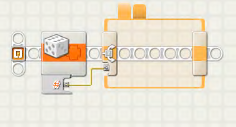
For this example, I'm going to use the RANDOM block that is discussed in Chapter 14. For now, don't worry about how it works—just drag and drop a RANDOM block from the Complete Palette onto the beam, and place it in front of the SWITCH block, as shown in Figure 12-10. (If you really want to know how the RANDOM block works, just jump ahead and read Chapter 14. I'll wait for you right here.)

For the configuration panel of the RANDOM block, simply enter a value of 1 in the Minimum text field and a value of 3 in the Maximum text field, as shown in Figure 12-10.
Drag a data wire from the RANDOM block to the SWITCH block (see Figure 12-11).
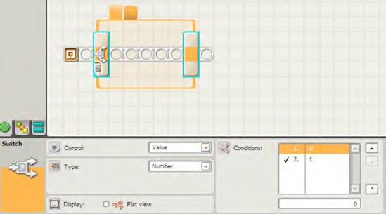
Next, you need to configure the SWITCH block to accept more than two conditions. To do this, click the SWITCH block again (if it isn't already selected), and look at the configuration panel. On the left side of the configuration panel, you'll see the Conditions section (shown in Figure 12-12).

Let me explain what you are looking at. This is a list consisting of path numbers. Each path number has a default value that the SWITCH block will check. In this example, you see the following:
0
1
The 1 and 2 on the left are the possible conditions, and these match the number of tabs you see along the top edge of the SWITCH block. The 0 and 1 values in the right column are the default Number values that the SWITCH block will use to pick a path. For example, if the Number value coming into the SWITCH block's data plug is 0, then the first condition will be selected, and any blocks found under the first tab will be executed.
But you need three conditions—one for each if the RANDOM block generates the number 1, 2, or 3. To do this, click on the small plus button (+) in Figure 12-12. It adds the third condition and automatically configures it with a default value of 2. This is seen in Figure 12-13. If you click on the new condition, you can change the default value of 2 to any number you like. You're going to need to do that shortly.

Notice that there is now a new row in the Condition section:
0
1
2
There are now three tabs on the SWITCH block. Tab 3 will have its blocks executed if the SWITCH block detects a Number value of 2.
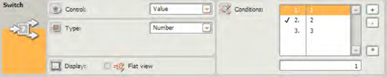
Here you have a small problem: SPOT will pick only 1, 2, or 3. But the only options shown are 0, 1, and 2. How can you change this? If you click one of the conditions, you can change its value in the text box just below the Condition section. First, click the condition whose value you want to change (see Figure 12-14).

In this example, the third condition is selected, which has a default value of 2. In the box below the conditions, enter the value of 3 as seen in Figure 12-15 and press Enter.

You'll do this for the first and second conditions also, changing their respective values to 1 and 2, as seen in Figure 12-16.
Finally, you may have noticed the checkmark next to a condition. In Figure 12-16 it is next to the second condition (indicated by the numeral 2). The checkmark indicates which condition the SWITCH block considers the default value to use and the tab (and its blocks) to select if the SWITCH block is unable to make a decision. For example, suppose I had configured the RANDOM block to select a value between 1 and 5. There are no conditions specified for what to do if a 4 or 5 is randomly selected. Suppose you wish a 4 or 5 to be treated as a value of 3. In this case, the blocks found on the third tab will be executed because you have selected condition 3 by selecting the third condition and clicking on the small asterisk button (*), as seen in Figure 12-17.

Note
When a SWITCH block is encountered, something must be done. One of the conditions must be satisfied for the program to continue running. Therefore, a default condition must be specified in most instances. You can always leave a path empty, with no NXT-G blocks on it, for one of the conditions. In cases where you have a program that should not react to a condition, provide a blank path and set that blank path as the default. Then, if a sensor or RANDOM block or other block does not trigger a suitable condition you've specified for the SWITCH block, the default condition will be chosen and no blocks executed, allowing the SWITCH block to complete and the program to continue.
Warning
Please be aware that you cannot have two or more conditions with the same Number value. This is because the SWITCH block would get confused and not know which path to take. Make sense? If condition 1 has a Number value of 1 and condition 2 has a Number value of 1, which path would the SWITCH block take if the RANDOM block sends a value of 1? Fortunately, the SWITCH block is smart and will not allow you to make this mistake.
Now that you've configured the three conditions and the default (condition 3), you can drop in a collection of MOVE blocks that will allow SPOT to turn left, turn right, or move forward.
If SPOT picks 1, then he turns left. So, you'll click the first tab (see Figure 12-18) and drop in a MOVE block that will allow SPOT to turn left.

I'll do the same thing for the second and third tabs. When the RANDOM block generates a number from 1 to 3, that number is passed to the SWITCH block. The SWITCH block takes this Number value and compares it to the values in its Condition section. If the RANDOM block sends a 3, the SWITCH blocks takes that value, notices that it equals the 3 in the third condition, and then executes any blocks found on the third tab. Easy!
One final warning, though—what happens if the RANDOM block goes crazy and sends a value of 4 or 5 to the SWITCH block? There is no condition that has a matching value of 4 or 5, so what will happen? Well, remember when you selected a condition and clicked the * button and a checkmark appeared next to the condition? That checkmark also specifies the default condition. Look back at Figure 12-17. The checkmark is next to the third condition. This means that if a value of 4 or 5 is provided by the RANDOM block, the default path will be chosen. So the blocks in the third tab will execute for a value of 4, 5, 100, or any other number except for 1 and 2.
The SWITCH block is a very useful block for giving your robots some powerful decision-making skills. The SWITCH block can use Logic values (True or False), Numbers, Text, and sensors to determine which paths are chosen by your robot to execute. Keep this in mind when you need to give your robots the ability to make different decisions based on different types of input.
As your programming skills progress, you'll find the SWITCH block one of your favorite tools to use.
Now, before leaving this chapter and moving on to some of the more advanced NXT-G blocks, I'd like for you to try creating an NXT-G program that satisfies the requirements found in Exercise 12-1. I've provided the answer at the end of the chapter if you get stuck.
Program SPOT to examine his surroundings and make some decisions based on sensor input. SPOT should move around the room as defined by these rules:
Move forward until the Color sensor detects a red or yellow piece of tape on the floor.
If a red piece of tape is detected, turn left 90 degrees and move forward 10 rotations.
If a yellow piece of tape is detected, turn right 90 degrees and move forward 10 rotations.
In the next few chapters, you'll be looking into some specialty blocks. You'll learn about a block to stop your robot's program execution. Believe it or not, stopping and doing nothing is sometimes exactly the right thing to do. After stopping, you'll learn about randomizing. There's much more to follow too, so don't stop reading.
The solution to Exercise 12-1 can be seen in Figures 12-19 through 12-24. Notice that the WAIT block is first used to detect a colored piece of tape (red or yellow), specified by dragging the condition bars on the COLOR SENSOR WAIT block's configuration panel. Once a red or yellow piece of tape is discovered, the SWITCH block will examine the tape and determine if it is red in color. If it is, the condition specified in Figure 12-21 is true and the MOVE block in the top portion of the SWITCH block will execute (see Figure 12-22). If the tape isn't red, then it must be yellow (because the COLOR SENSOR WAIT block stops only for red or yellow) and this will force the lower portion of the SWITCH block to execute its MOVE block seen in Figure 12-23 (rotating the robot to the right). After a turn is made, the final MOVE block (see Figure 12-24) will have the robot roll forward 10 rotations.