Physically constructing a home studio isn’t as simple as just buying a lot of wood and putting it together. There’s a lot of thought and planning that has to go into this project in order for it to come out right. Deciding what you need and how to construct it in a manner that achieves your goal is probably more work than the actual work itself. In this chapter, you’ll examine the options you have for various construction types, as well as the pros and cons of those techniques. By the end of this chapter, you should be well prepared to make the decisions you need to proceed with your design.
In more cases than not in a home recording studio, you’ll be trying to fit your room(s) within existing spaces. Hopefully, these spaces will be located on concrete slabs. I say that because it is much easier to achieve adequate isolation on concrete slabs than on elevated wooden decks. We’ll spend a little bit of time looking at the “whys” of that later in this section.
Simple concrete slabs are what you would typically see in your basement or garage. They are generally 4 to 5″ thick and probably don’t have much in the way of reinforcing within the slab itself—that’s if they have any reinforcing at all. The slab is poured above compacted earth, usually above a vapor barrier. It might even have some type of wire mesh in it, but this is intended to be at the top of the slab for shrinkage control, and does not really add any structural strength to the slab itself. Besides which, it is almost always placed badly (even for that purpose) due to the manner in which it is typically installed, which is lying flat on the ground, with the crew (who are placing the concrete) using their concrete rakes to pick it up into place. Not a good recipe to ensure consistent placement.
If a room within a room is constructed on an existing simple slab (as you might see in a garage with wood-framed exterior walls), sound can transmit through the slab and surrounding foundation itself into adjacent spaces. However, this sound transmission will probably be minimal compared to what loss you will have with ceiling and wall assemblies, depending on the building structure.
In the case of a full basement (walls buried below grade), the sound could also transmit through the slab into the foundation wall and then into the structure above. However, for the most part, earth is a fairly good damping material, and generally you can obtain the isolation you require by simply constructing your space above that existing slab.
Isolated concrete slabs are those that are poured on earth, but only to the outside face of the walls for the room that sits on them. These are excellent slabs for studio design and that’s how we constructed the slabs for Power Station New England. After pouring the main slab for the first room, a separate slab was poured adjacent to, but not touching, the first slab. The space between the two slabs was treated with an expansion joint material and then caulked to seal out moisture.
Figure 4.1 indicates typical details used for isolated slab construction. Note the use of the haunch at the slab edge. A haunch is a thickened section of concrete that is poured monolithically with a slab, in order to form what is effectively a footing capable of carrying a structural load.
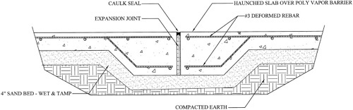
This is created to provide adequate bearing for the room walls, which will sit on top of the slab in that location. There is a school of thought that a simple slab can be turned into an isolated slab simply by saw-cutting the slab in between the party walls of separate rooms. I don’t suggest this method, due to the fact that a simple slab is not designed to carry a room load on its edge. It is very possible that the slab could crack and settle along the edge, causing problems with room finishes down the road. This is the sort of thing that you may not experience until after all the load (superimposed on the slab) is in place. It’s a pain in the neck to finish your room, be fairly happy with your product, and suddenly have a wall on one corner settle ¼″ or more. The best scenario would be to remove the existing slab at least enough to install a proper haunch at the wall edge and then use a bonding agent to join the new to the old. If the existing slab has reinforcing in it, all the better, because you can remove the concrete without destroying the reinforcing and use it to help tie the new to the existing.
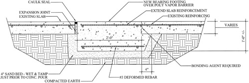
Figure 4.2 indicates the details for adding bearing capacity to your existing slab. Note how the new slab/haunch pours slightly under the existing slab. This is referred to as underpinning, which helps to ensure that the two members act as one. You do not want the sections to act independently from one another.
By the way, just so you understand completely, this is not easy work. First, you really want to know if the slab has some reinforcing you can use to tie the old and new together. This requires the use of a jackhammer to open up a section of slab or special equipment to perform testing of the slab. Both pneumatic and electric jackhammers are readily available at all local equipment rental centers. The electric will not provide the same working speed as pneumatic, but it is easier to work with, due to the ease of running cable versus 1 ¼″ hose and the tendency to weigh less. The testing equipment is generally not available for rental purposes and would require you to hire a consultant to test it or the purchase of the equipment, which is not inexpensive. Chances are that you will use the hammer. If you do find rebar or reinforcing wire installed within the slab, then the entire work must be done with that same jackhammer. As I mentioned earlier, it’s a lot of work.
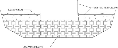
Locate the outside face of your room wall and snap a chalk line. At this point, you will saw-cut through the entire slab thickness. Use your jackhammer to carefully remove enough concrete to determine whether slab reinforcing exists. If it does, then locate a line about 2′ inside of your room from the existing line. At this location, you will want to adjust your saw to cut only ½″ deep into the concrete. This will provide a professional looking joint to finish your new concrete. Jackhammer out all the concrete into small pieces, which can be removed without removing the reinforcing. Save as much of the reinforcing as you possibly can. You will then have to bend that up along the face of the concrete in order to excavate for your new bearing point. Figure 4.3 indicates the condition that should exist at this point.
Excavate for your new concrete, making certain to remove at least 4” of material underneath the existing slab for bearing, then install your expansion joint (a couple of pieces of expansive foam typically used for “sill seal” is perfect for this purpose), and bend the rebar down into place. Pour your new haunch, using the existing concrete surface as your screed. When it’s cured, you can clean the edge and caulk.
If you find no rebar in your slab, then you can just saw-cut the concrete in the second location full depth and remove the concrete in larger sections. In this case, when you excavate, you should make certain to underpin the existing slab a minimum of 8”. Figure 4.4 indicates a section through the finished product in this condition.
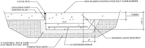
Prior to pouring your concrete haunch, you will want to cover the edge of the existing concrete with a bonding agent made for that purpose. Sika Corporation manufacturers a product called SikaDur Hi Mod, which is an excellent bonding agent that I have had great success with in the past. Simply follow the manufacturer’s instructions for a fail-safe installation.
Floating concrete slabs are also excellent products for sound isolation, if designed and constructed properly. They are also very expensive, a tremendous amount of work, and on the low end of recommendations I would make for a home studio. I will include information here, but unless you are very serious about spending the time, effort, and money to obtain nothing shy of professional results in your home studio, I would not suggest that you bother including them for consideration. The slabs must be designed for a center frequency of no greater than 10Hz, and they only really make sense if you are going to achieve the same results with your wall and ceiling assemblies as you do with your slab. For this purpose, picture seven layers of drywall on your wall and ceiling assemblies.
Figure 4.5 is one product manufactured by Mason Industries for the purpose of constructing an elevated concrete slab.
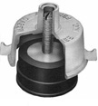
Figure 4.5. To construct an elevated concrete slab, you can use the Mason jack-up floor slab system.
This is a lift slab product, utilizing a neoprene puck as the spring in the system. With this product, you can pour a new slab directly over an existing slab (thus saving on the bottom formwork required to pour an elevated slab in place). Figure 4.6 is another member of the Mason Industries family. It’s an FS Spring Jack, which utilizes a coil spring instead of the neoprene isolator.
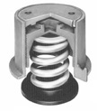
Both systems will work very well when the slab is properly designed, but for the purposes of examples in this book, we will use the neoprene puck system.
There’s something you need to understand if you plan on using this method of construction. Lightweight concrete weighs as much as 115pcf (pounds per cubic foot). The spacing of the supports for this particular system can be as great as 54″ on center. That translates to 20.25s.f. (square feet) per support, which, with a 6″-thick slab, would be 1,164 pounds per support. That’s just for the slab. In addition to this, you will have the load imposed by the new walls and ceiling. It’s quite possible that a simple slab would not be able to take this loading; for example, that you could have cracking and settlement of the existing slab, which would destroy your new work. We typically pour reinforced concrete with a series of mini haunches to carry pin loads like this in new construction. It is very important that you contact a structural engineer to assess your existing structure if you plan to use this method as a part of your studio design.
I promised you I would not bury you in math in this book, and I intend to keep that promise. There are calculations that need to be performed to design your slab to the required 10Hz center frequency, but I’m not giving them to you. It is so much easier for you to contact the manufacturer directly, and they will happily perform those calculations as a part of their service in selling their product to you. You will be required to provide them with detailed information about your construction, so it isn’t as if you can decide today that you want this without planning your entire studio at the same time.
The design of these slabs is based on the slab weight itself, the weight of all walls and ceiling loads (including finishes), and the weight of equipment to be placed permanently within the room. (This is what makes up your actual and superimposed dead loads.) Then you have to figure out what your live loads will be. This should be a fairly accurate assessment of people and gear that will be brought into the space.
Floating slab isolation is based on a Mass Spring Mass (MSM) system. The first Mass is the element the slab will be supported by. The Spring is (in this case) the Dupont Neoprene pad sitting below the lift mechanism. The second Mass is the elevated slab itself. The reason for identifying all of the imposed loads properly is due to the fact that for an MSM system to operate properly, you must load the spring just enough to fully engage it. Overloading (over-compressing) the spring will cause the system to fail because the sound will transmit directly through the spring. Underloading (thus undercompressing) will cause the same effect. It’s the combination of the mass and the air gap that provides your insulation. You do not want the spring to create a flanking path of its own.
The air gap is an important factor to take into consideration when using this system. For example, tests performed at the Riverbank Laboratories in Geneva, Illinois, proved that pouring a 4″ slab over an original 6″ slab only increased isolation from STC 54 to 57. Adding a 2″ sealed airspace raises the STC to 79. Doubling the airspace to 4″ increased this to STC 82.
In reality, if you have a slab with a resonant frequency of 10Hz and an STC rating of 79, you will be stretching it to achieve this with the remainder of your room construction.
After your design is finalized, you’ll lay out your grid, install your edge forming, and place the lifts on the intersecting points (see Figure 4.7). The spacing at the slab edge will often be closer than the spacing in the field (center) of the slab. This is due to the load that will be imposed on the slab edge by the walls and ceiling.
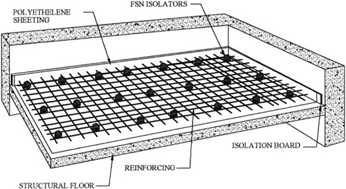
Rebar is then installed and supported by the hooks you see on the lifts. You need to make certain to tie your rebar together using “tie wire,” which can be purchased in rolls at any lumberyard. A couple of turns around the rebar, where two bars intersect, and a few twists of the wire together to lock it into place, and you’re all set. This will ensure that the rebar stays put when you place the concrete. It won’t do you any good if it’s lying on the bottom of the slab when the pour is complete.
Edge forming isn’t all that difficult in this case. You can do this with 2x6 or 2x8 framing lumber for the sides (depending on your slab thickness) with 2x4 framing to lock them into place. The tops should be straight and true; then they can be tied in with 2x4 braces. You can use a builder’s dumpy level or a laser (both are available from any tool rental company) to strike a level line completely around the slab. Mark the sides of the forms and then use 6- or 8-penny finish nails to mark the finish height of your slab. These are easier to pour than trying to use a line that gets covered with concrete and becomes invisible. Just tap them about ¾″ into the form to lock them securely into place.
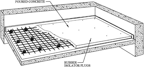
A lot of people say that floor finish depends on floor covering, or that if you plan on covering it up you don’t have to be too fussy. They’re wrong. The better the quality of finish you provide to the floor, the flatter the floor will be in the end. And flat is important if you want to put down wood flooring and not have it make funny noises. I’m not going to try to teach you here how to pour and finish a concrete slab. If you don’t know that already, you would be much better off paying someone experienced to do the work for you. Figure 4.8 shows the conditions expected during the concrete pour. Make sure to install the rubber plugs prior to the pour, which ensures that no concrete can enter the threaded chamber of the slab lift.
One trick you can use to help you along is to rent a laser level. You can set this to your finish slab height and use it to maintain the proper screed height as you go along. We don’t generally use pipe screeds anymore in the industry; this equipment is the only way to go. If you do this yourself, make sure to set the instrument to a fine setting (⅛″). This will help ensure a flat surface when you’re finished.
You are going to have to let your concrete fully cure before you begin to lift the slab. Don’t even consider lifting the slab for the first 28 days. Twenty-eight days is typically the point where concrete will cure to its designed strength. In order to ensure that the concrete cures properly, you will want to flood it with water after finishing and then cover it with a layer of poly. Be certain to check it at least once a week (or sooner) to make sure it stays wet; this is an important part of the curing process. There are also curing compounds you can use for this purpose, but the least expensive manner is simply water.
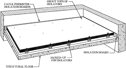
After the concrete finishes curing, remove the forms, lift the slab, and you’re ready to begin work on the studio walls. Figure 4.9 shows a slab in the elevated position before any additional work is in place.
For the actual results you might expect with this system, we provide the following data from tests performed for Mason Industries.
The test specimen consisted of a 4-inch thick reinforced concrete slab, with an average weight of 50lb. per square foot, supported on a grid of Mason Industries Type FSN-1336 and 1337 mountings with Type EAFM neoprene elements. The mountings are spaced on 24-inch centers, supporting the 4-inch thick “floating slab,” 2 inches above a 5-1/2lb. per square foot elevated composite concrete slab. The floating slab was finished in the studio with a layer of 1/8-inch linoleum flooring. The floating slab was isolated along its perimeter with Type 34AFG-10, 3/4-inch thick, 10lb. density fiberglass boards. The test surface area was 1,054 square feet.
The test method used in obtaining the data is in accordance with ISO (International Standards Organization) Recommendation R-140-1960, “Field and Laboratory Measurement of Airborne and Impact Sound Transmission.”
The data obtained were corrected to a reference room-absorption of 10 square meters. In accordance with the R-140-1960 Standard Recommendations, the absorption of the receiving room was measured by recording the acoustical decay rate.
Test equipment consisted of the Bruel & Kjaer Tapping Machine Type 3204, which was placed at two (2) positions on the test floor. Sound pressure levels were measured in one-third octave bands in the receiving room by using the General Radio Noise and Vibration Analyzer Type 156A, and corrected for ambient noise levels in the receiving room. Test results represent the arithmetic average of the two positions measured. These positions are indicated with “X” marks on drawings Z-1075-1.
The test was conducted in full conformity with Section 6 of American Society for Testing and Materials Designations E 336-71, Standard Recommended Practice for Measurement of Airborne Sound Insulation in Buildings.
Acoustical test signals of prerecorded 1/3 octave band random noise were generated in the source room with loudspeakers placed in such manners as to generate a diffused sound field. Four loudspeakers were used consisting of two 8-inch diameter acoustically suspended speakers, and two horn speakers.
Test frequencies were 1/3-octave band frequencies between 100 and 5,000Hz inclusive. Sound pressure levels were measured in the receiving room in 1/3 octaves by using the General Radio Noise and Vibration Analyzer Type 1564A, and corrected for ambient noise levels in the receiving room. The data obtained were corrected to a reference room-absorption of 10 square meters. In accordance with the ASTM E336-71 Test Standard, the absorption of the receiving room was measured by recording the acoustical decay rate.
The test specimen separates the 25th floor TV studio and elevator equipment room on the 24th floor. For the impact test, the receiving room was the elevator equipment room. Measurements were made in the elevator equipment room in the late evening hours with all elevator equipment, as well as ventilation equipment, shut down in order to permit measurable sound pressure levels tied to the Tapping Machine.
For the Airborne Sound Transmission Test, the elevator equipment room was used as the source room and the TV Studio was used as the receiving room so as to minimize the amount of time elevator equipment was shut down. Partitions around the TV Studio were partially supported on the test specimen floor as shown on Mason Industries drawing Z-1076. Furthermore, the ceiling over the TV Studio consisted of a resiliently suspended gypboard ceiling with a layer of 4-inch thick glass fiber blanket laid over the top.
Sound pressure levels at 1/3 octave intervals, normalized to 10 square meters, are as follows:
Center Frequency (Hz) in One-Third Octave Bands | Sound Pressure Levels (dB) Normalized to Ao = 10 M sq |
|---|---|
100 | 51 |
125 | 49 |
160 | 48 |
200 | 48 |
250 | 47 |
315 | 42 |
400 | 36 |
500 | 34 |
630 | 28 |
800 | 29 |
1000 | 28 |
1250 | 24 |
1600 | 24 |
000 2500 3150 | * |
Impact Noise Rating | INR + 24 |
Note: * Denotes sound pressure levels due to Tapping Machine being below ambient noise levels for those frequencies indicated. | |
Sound transmission loss values are tabulated below at the 18 standard test frequencies.
Center Frequency (Hz) in One-Third Octave Bands | Transmission Loss (dB) Normalized to Ao = 10 M sq |
|---|---|
100 | 47 |
125 | 48 |
160 | 50 |
200 | 54 |
250 | 60 |
315 | 66 |
400 | 71 |
500 | 79 |
630 | 85 |
800 | 90 |
1000 | 95 |
1250 | 92 |
1600 | 92 |
2000 2500 3150 4000 5000 | * |
Field Sound Transmission Class | FSTC – 71 |
Note: *Denotes transmitted sound pressure levels being below the ambient noise levels for those frequencies indicated. “[1] | |
One of the things I like about this test data is that it gives us a chance to look at the differences between laboratory tests and real-world field conditions. The expected Impact Noise Rating (INR), based on lab testing, was INR + 17, which in the field test yielded a result of INR + 24, a fairly significant increase in isolation. This was attributed to ⅛″ linoleum flooring placed on the field specimen versus a bare concrete slab in the lab. Also, part of the increase was apparently due to the supporting slab itself, which was a rigid structural slab (in the real world) compared to the precast “T” section concrete panels used in the laboratory tests. The impact rating could obviously go in either direction, based on field versus lab structural differences.
The difference in STC rating was as follows:
Laboratory STC rating was 79 vs. FSTC rating of 71.
(The F in FSTC stands for “Field,” i.e., the real world.)
Once again, this is a very significant difference. An 8dB reduction (in isolation) of the final assembly in the field application (although not surprising to me) means that the noise making it through to the other side is more than two times louder than expected by lab results. The apparent reasons for this were that the walls surrounding the studio were capable of less sound attenuation than the slab itself. The partitions in the studio were drywall vs. masonry partitions used in the lab. Also, a single layer of gypsum was installed in the ceiling of the studio. This was not capable of matching the double layer used in the lab. The walls in the studio were constructed to the underside of the structure above. The single-layer drywall ceiling (coupled with the wall assembly’s attachment to structure) allowed sound to travel through the building structure outside of the TV studio and then into it. This is an example of flanking noise affecting your total sound isolation.
The third item has to do with something I’ve mentioned earlier in discussions here and that involves the quality of work performed in the field by the professionals in the construction industry. In lab tests performed by a bona-fide laboratory, the construction is as close to perfect as is physically possible. Care is taken to provide properly installed and sealed assemblies. In the real world (the world that your construction will take place), contractors have a vested interest in getting in and out of the project. It’s not that they don’t really care about the finished product, but they don’t necessarily devote the attention to detail that takes place in that laboratory. Many times the person who bids the work never even sees the job. The workers in the field never receive the information they need to understand exactly what steps need to be taken or the order they need to be taken in.
In addition, they see some of what we (the owners and engineers) place importance on (which is that same care taken in the labs) as being less than necessary for a “decent job.” They do not understand the importance, they think it’s overkill, and they think that the small difference in quality won’t mean a whole lot in the end. They could not be more wrong.
One other point I will make here before moving on is that the test result you see only relates to a floor-to-floor separation and not room-to-room. I can guarantee that the wall and ceiling construction used for this studio would not come anywhere near the STC 71 reported here floor to floor, and thus the money for the floating slab would have been wasted if that were a concern.
In the case of this TV studio, apparently their biggest challenge was noise being transmitted from the elevator machine room into the studio. In this case, it paid off. In your case, however, it’s going to be a concern for you with your neighbors and family. So unless you plan on going the full route, meaning that unless you plan on building a “bomb shelter” to record in, don’t waste your money by taking this path. You can get some fabulous results with a floating room on a floating slab if you need them, but you have to make it all work as a whole—one piece won’t get it done by itself.
I will spend just a moment discussing decks because I hope to save you some money and aggravation. I wish I had a dime for every time I’ve seen someone ask (on an Internet site) how to calculate the spacing of pucks for a floating wood deck. I know immediately that they do not have a clue what they’re building. Someone, somewhere, just told them that they needed to float a deck in order to get real isolation, and they listened.
Reality is that you can’t get isolation for a recording studio with a simple elevated wood deck. Period.
Elevated wooden decks are great for impact noise, so they’ll work well in dance studios, bowling alleys, condos, etc., but they do not have enough mass to isolate a recording studio properly. The frequencies of the bass drum and bass guitar are too low to be handled with a deck of this nature.
Another problem with isolated wood decks (and this again relates to the lack of mass) is that the resonant frequency of the deck itself may create problems. As I pointed out with the elevated concrete decks earlier, the resonant frequency of the deck needs to be around 10Hz. With concrete, achieving that frequency is a matter of proper design; with a wood-framed deck, it’s a matter of being so close to impossible that it isn’t worth the effort or expense.
For example, I recently came in contact with someone who owns a professional studio, with some of their rooms rented for space for practice, and others for tracking and control rooms. They were inquiring about the density of the insulation they should use in these already-built isolating decks they constructed. I explained to them the problems they were going to experience, but they apparently did not believe me. They completed their construction (based on “expert advice” they received from others) and then came back to let me know about the problems they were having with these “drumheads” they built. Frequencies between 200 and 400Hz were being amplified by the deck construction, and they wanted to know what they could do to solve the problem. My answer to them was to either remove the decking and fill the frame completely with dry sand or remove the decks in their entirety.
Seeing as this is a (roughly) 3,000s.f. facility, that translates to a lot of wasted materials and labor any way you look at it. All of the decks were filled with mineral wool and then multiple layers of decking plus finished floors. Picture the cost of that construction and now add to it the cost of removing those finished floors and decks—pull out that mineral wool (throw it away because it isn’t going to do you any good anymore)—now bring sand in and begin finishing these spaces all over again.
So please, I don’t care what your friends tell you. I don’t care what some “expert” on the Internet tells you. Save your money. It’s too precious to just throw away.
Unlike elevated wood decks, sand-filled decks can be of some benefit. One benefit is the creation of a pathway below the floor to route low-voltage (LV) wiring (through the use of PVC conduits). It’s a big advantage if the LV wiring can be separated from line-voltage cable runs (plugs, lighting, etc.).
You can also gain some small benefit from an isolation point of view, which is due to the ability of the sand to damp sound vibrations.
However, this is a very heavy assembly (sand alone weighs roughly 100pcf) and (as in the case of concrete slabs) will require a structural engineer to confirm that you can safely install this on your existing structure.
Wall construction is not really all that involved, provided you pay attention to details. Your biggest challenge is to determine what level of isolation you need, the amount of mass you need to handle that, and then to make certain to put everything in the right location.
The right location. Think about that for a moment. There is actually a right location for materials.
Yup, there sure is.
Look at Figure 4.10 for a moment.
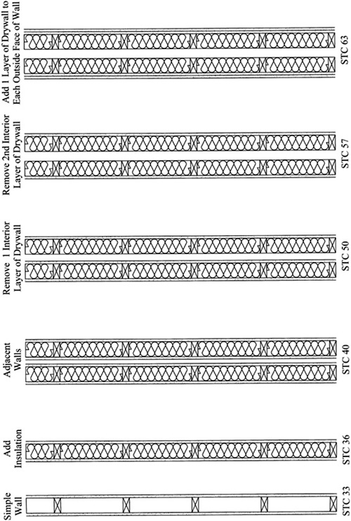
Note that the wall assembly third from the left has an STC rating of 40dB. It is constructed using two separate wall frames with four layers of drywall total and with insulation installed in the cavities of both walls. The drywall is installed on both faces of each wall assembly.
If we remove one inside layer, note how the STC rating rises from 40 to 50. Remove the second layer, and it rises another 7dB of isolation to 57. Now take those two layers and install them over the two faces of the outside wall, and you add another 6dB of isolation for a total of STC 63.
This is a 23dB increase in isolation using exactly the same materials in different locations!
That’s an amazing increase in isolation, and it didn’t cost a single additional penny to gain it.
This appears to fly directly in the face of what I told you earlier—that each doubling of mass adds roughly 6dB of isolation to your wall. However, the reason for this has nothing to do with the amount of mass and everything to do with the location of that mass.
Consider that each different location of the drywall constitutes a leaf. In the case of the STC 40 wall assembly, you have two walls with one layer on each wall face, thus, a four-leaf system. You count the leafs thus: Mass, Air, Mass, Air, Mass, Air, Mass. Each area of mass (drywall) equals one leaf. When you remove one inner face, it becomes a three-leaf system and then a two-leaf system when you remove the last inside face of drywall. A two-leaf system with ½ the mass of the four-leaf system will provide almost eight times greater isolation. It is at that point that the doubling of the mass becomes what I told you earlier. Note the 6dB increase from the STC 57 to 63 when the mass is doubled and put in the correct location.
So get a picture firmly in your mind—two-leaf wall systems are good, two-leaf wall systems are your friends. Three- and four-leaf wall systems are evil devious fiends that suck up the money in your wallets and give you less than nothing in return.
So when you build, strive for two-leaf wall systems and nothing else. These wall assemblies are Mass Air Mass (MAM) Systems. With MAM systems, the air between the leaf walls becomes the spring. Thus, sound pressure builds up within the space striking the wall surface and causing it to deflect inward. This compresses the air within the space, which causes the outer surface to deflect outward. The compressed air becomes the spring. The transfer of sound is its vibrational energy traveling through the spring from one layer to the other. If this energy rested within the frequency range of the wall assembly, it would cause a fairly significant lowering of the TL (transmission loss) of the assembly. The more mass you add, coupled with the air space and the stiffness of the assembly, all help to lower the resonant frequency of the assembly.
Existing walls are going to be your biggest challenge. The exterior walls are probably a long way away from being airtight. Interior walls might be running parallel with a corridor, and perhaps that corridor is already only 36” wide, which means you can’t add more mass to the corridor wall without creating a violation of the building code by creating a corridor whose width is too narrow. Maybe your building is in a basement and has to contend with windows, perhaps large gaps between the foundation and the plate that carries the deck framing. Or you are using an existing bedroom that the building official requires to remain as is, with the egress windows intact.
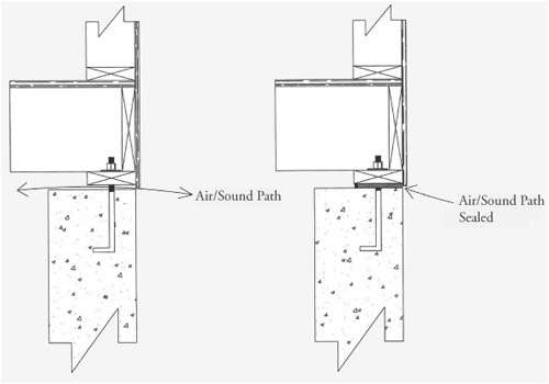
In all these cases, there are solutions to your problems. In the case of the concrete foundation, you can fill those cracks between the plate and concrete with mineral wool. Just pack it well to make certain you have good density and then caulk the joint between the two with acoustic caulk.
Figure 4.11 indicates both the original condition of the foundation and the finished seal.
In the case of that corridor wall, you can remove the drywall on your room side and install additional mass within the wall cavity itself, which will go a long way toward helping your isolation.
We will look at the actual construction of these assemblies in the next chapter. For now, let’s look at the various types of wall assemblies and their possible benefits or drawbacks.
Wood is one of my personal favorites when it comes to studio construction. There’s just something beautiful about a properly framed wood wall. In the days when I used to swing a hammer, we had a saying about wood framing, “It should be so pretty you don’t have to cover it up.”
Let’s focus on the options.
Single-wall construction is what you’re used to seeing in your home. It’s a simple wall—typically a single 2x4 or 2x6 plate—with studs ranging from 16″ to 24″ on center (oc). It probably has double top plates and usually a layer of ½″ gypsum drywall mounted on each of the faces.
You already know it’s not a good isolator, or you wouldn’t be reading this book.
Take that same wall and add resilient channel to one side of it (after removing the existing layer of drywall). This decouples the layer of gypsum on that face from the framing behind it. With that same layer of ½″ gypsum, you just increased your isolation from somewhere between 3 and 5dB.
There are many different types of resilient channels on the market today, as well as materials you might mistake for resilient channels, for example, hat channels or Z channels. RC-1 is a single-leg channel primarily used for walls. RC-2 is a double-legged channel primarily used for ceilings.
Figure 4.12 is a picture of various types of resilient channels. I have also included a section of hat channel. Note that hat channel does not have any holes or slots along its “leg.” The slots and holes are one of the main reasons that the members isolate in the manner they do. Without them, isolation is nil.
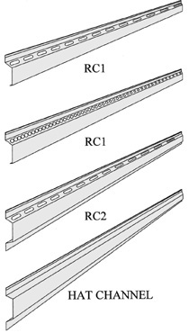
You can use either RC-1 or RC-2 for walls and ceilings; however, RC-1 used on a ceiling will not support the same load as the RC-2.
Figure 4.13 shows RC-1 installed properly on 2x4 framing. Note that the flange is installed in the bottom position. It is important that these products be installed correctly to ensure that they isolate properly.
Make certain to be very careful that you do not use the hat channel or standard Z channel instead of RC, because the net effect will be no gain in isolation with a lot of added material and labor costs. And, amazingly, there are a lot of drywall contractors out there who can’t tell the difference between the two. Whatever you decide to purchase, make sure to ask for (and receive) the technical data as a part of the purchase. This will ensure that you’re getting the right material.
RISC 1 clips (resilient sound isolation clips) are another excellent way to decouple drywall from a structure (see Figure 4.14). These products use a rubber isolator to decouple the clip from the stud, and a hat channel is then mounted into the clip to attach the drywall. This unit will typically provide around a 6 to 8dB increase in isolation over what you can expect using standard resilient channel. Once again, there are several different manufacturers of this type of product.
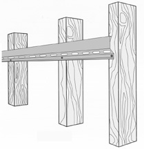
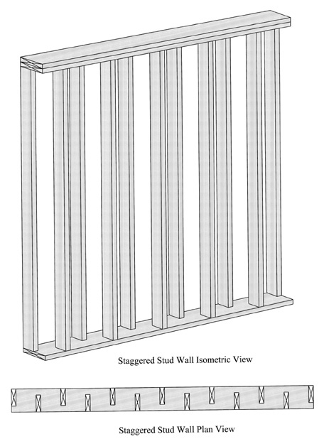
Dual wood-framed wall assemblies come in a few different types. One of these is a staggered stud configuration, with single top and bottom plates (typically 2x6 or 2x8), with the studs staggered from one another on opposite sides of the wall. With framing 16″ oc, that would place the studs on 8″ centers and 12″ centers for 24″ framing. Figure 4.15 is a view of a typical staggered stud system.
The advantage is greater isolation than the use of single-frame walls, decoupling the drywall surfaces from one another reduces the need for RC or RISC systems.
The disadvantage is that the common top and bottom plates become the weak points of this system, effectively acting as a bridge from one side to the other. This direct passage weakens an otherwise good system.
True isolated wall assemblies use separate top and bottom plates, as well as separate studs, which effectively completely decouples each wall from one another. Figure 4.16 is an example of double-framed wall assemblies.
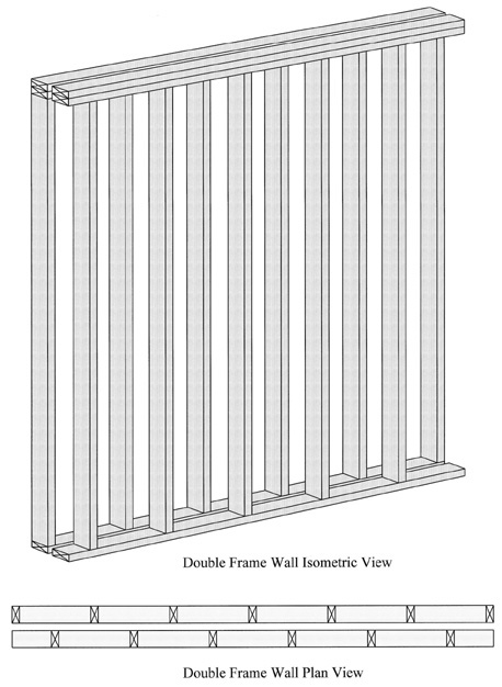
One point I want to be sure you get is that there is no advantage to using isolating clips or resilient channel with a true double wall assembly. Don’t waste your money by thinking that more is better in this case. The only thing that should be more with a double wall system is mass and (perhaps) constrained layer damping.
The advantage to this is that it’s not much more money than a staggered stud wall assembly, and it can achieve much greater isolation that any of the clip systems. The disadvantage is that it takes up more real estate (by this I mean room space) than the RISC, RC systems, or a simple staggered stud system with common top and bottom plates.
However, when isolation requirements are high, and you weigh the isolation benefit vs. the cost per square foot of construction, then the added isolation can be such a dramatic increase that the added cost is well worth the investment. You will reach a limit with the other systems (based on common connection points between the adjacent spaces), such that the flanking action of the frames will become the weak point. This is one of the great strengths of a double frame assembly.
Now, let me clarify that last statement. In all assemblies—unless care is taken to address flanking paths—there will come a point where the passage of flanking noise will take place over the value of the sum of the separate assemblies. In actuality, flanking will always be the deciding factor in the total isolating value of an assembly. But you can go a long way toward raising the level of isolation by making certain you do not have any hard connections between adjacent structures. As an example, it would do you no good to build wall and ceiling assemblies with 70dB isolating values if you’re on the second floor of a building and are sitting on a deck assembly, which is structurally connected to other parts of the building.
The sound that travels through the building structure will not decrease just because you continue to add more mass to the walls. If you can’t create a condition where all of the elements of the assembly are balanced, then you will soon reach the point where you are throwing money at a problem without moving any closer to solving that problem.
Steel framing has some advantages over wood framing. It doesn’t shrink, twist, or burn. It’s a very stable material with uniform dimensions. Perfect fits are not as critical with steel framing as with wood. Fastening is as simple as screwing in a couple of self-tapping framing screws.
When we refer to heavy-gauge steel framing, it’s any material with a gauge greater than 25, whereas 25 gauge or lighter framing is considered lightweight steel framing.
Light-gauge steel framing has an advantage over wood framing or heavy-gauge steel framing because a wall constructed with it has a greater STC rating than a similar wood or heavy-gauge frame. So a simple wall framed with light-gauge framing and drywall applied directly to both sides will achieve the same STC rating as a wood frame wall with resilient channel installed.
The disadvantage of light-gauge framing is that it will not carry loads that wood framing will carry with ease. Heavy-gauge metal framing will carry the required loads, but it is generally more expensive than similar walls manufactured with wood and (from an isolation point of view) will provide the same results as wood.
A good read if you want to use steel frame construction is the USG Gypsum Construction Handbook. This handbook is a great source of information on this type of construction. It can be located here:
www.usg.com/resource-center/gypsum-construction-handbook.html
Another excellent reference for steel frame construction is the Dietrich Trade Ready Design Guide, which is full of engineering information as well as details for construction related to steel framing. It can be found at:
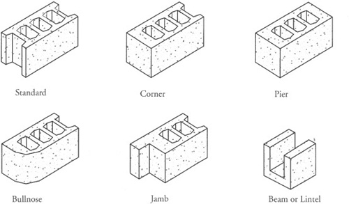
The use of concrete and masonry block to construct isolation walls is another effective means of accomplishing your goals.
In some parts of the world, masonry construction is preferred over wood due to the difficulty in obtaining structural wood framing materials and because it is the least expensive method of construction.
Standard hollow masonry blocks are readily available in nominal 8x8x16 inch dimensions. You’ll take a closer look at this in Chapter 10. See Figure 4.17 below to view typical block shapes.
“One man’s ceiling is another man’s floor.” Paul Simon, 1973.
Isn’t it always the way? You want to make music, and some inconsiderate human being wants to quietly read a book, sleep, settle a baby down, etc. (Fill in the blank based on your situation at home.)
Constructing an isolated system is only as good as the weakest link in the assembly—with the greatest challenges being spaces directly above or below you.
Let’s take a look at those challenges and methods of maintaining isolation.
What steps can be taken to obtain isolation when building below other living spaces? First and foremost, keep your eyes on the basics—mass, mass, and more mass.
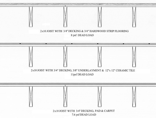
A typical deck in a modern home is generally ¾″ T&G (Tongue and Groove) plywood installed over floor joists or Truss Joist (TJIs), with possibly pad and carpet or hardwood floors installed directly over this. Kitchens and bathrooms will generally have an additional layer of ⅜″ plywood installed over the ¾″ deck, prior to the installation of resilient flooring or tile.
Figure 4.18 shows you some typical floor assemblies. Included are the approximate dead loads associated with these floors. Remember that the starting point for determining what may (or may not) be added to any structure begins with the existing structural capacity and weight.
One of the problems with just adding mass to the bottom of the existing joists is the transfer of sound directly through the joists themselves. Thus, the ceiling within your space has to be structurally decoupled from the floor above in some manner.
In addition to this, additional mass should be installed (if structurally possible) on the floor above. Remember that mass on both leaves of an isolation assembly is important. This floor/ceiling assembly is only different from your walls (acoustically speaking) in the sense that people walk on it, so the footfall noise (impact noise) adds another dimension to the challenges associated with isolation.
Once again, everything begins with a structural analysis of the existing assembly to determine what it is capable of carrying. Typical home design is mandated for a 10psf dead load and 40psf live load in kitchens, living rooms, family rooms, dining rooms, and game rooms. Bedrooms are typically designed for 10psf dead loads and 30psf live loads. The dead load is the weight of the floor joist, any decking above, and loads imparted by walls resting on the deck, along with the weight of floor coverings. The live loads are based on furniture within the space and the loads imparted by people within the room.
Although you may think that 40psf is a lot of capacity, when you look into an empty room and take into account your furniture, your spouse, and possibly a few children, it can suddenly become a critical load when you have a family reunion and 35 or 40 people fill up that room. (By the way, a family reunion on my mother’s side of the family may have as many as 350 direct family members show up, so big loadings are a real possibility.) The reason that I make this appear very important is because it really is.
Overloading a deck can cause long-term stress on it—with the result being a catastrophic structural failure when it receives a sudden additional load. I cannot stress the importance of this enough.
If you are designing a new home, it’s easy enough to determine what you need and make provisions for this in your design. Perhaps the placement of your studio above the garage—with an isolating mudroom connecting the garage to the house—would make sense. Or you could make sure you had a foundation that was 9 or 10 feet in height to allow enough room for a decent ceiling height in a basement studio, while maintaining completely isolated construction of the two spaces.
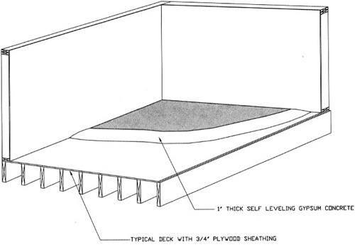
In this case, you would also want to add mass to the floor above and possibly even a lightweight concrete self-leveling slab (also known as gypsum concrete), which helps tremendously with isolating traffic noise. We use this all the time in hotel construction with wood-framed deck assemblies, gaining additional isolation, as well as creating a fire barrier between levels. See Figure 4.19 for a typical view of a wood deck with gypsum concrete being applied.
We’ll look more closely at some isolating decks for new construction in the next chapter. However, in existing construction, we begin with establishing what we can safely carry in additional dead loads before proceeding.
Now, assuming that your engineer sees no problems adding load to the structure, you can begin by installing gypsum board directly against the bottom of your existing deck assembly. Fit the board so that it is about ¼″ from your existing floor joist, hold it in place temporarily with some 4d finish nails, and caulk all edges. Add as many additional layers as your joist can safely carry (see Figure 4.20).
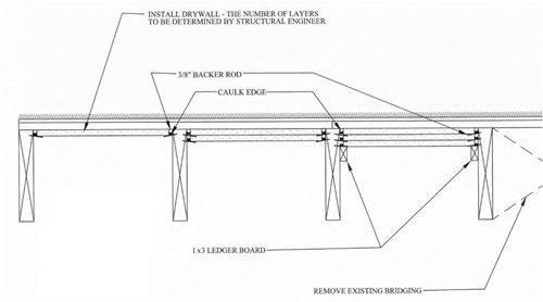
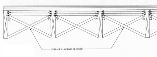
Generally, this will require the removal of some cross-bracing members (known as bridging) in your deck assembly. Make certain to replace these, as they are critical (structurally) to your original floor design (see Figure 4.21).
After all of this is in place (or back in place with the case of the bridging), you will want to insulate below that to the bottom of the floor joist. I have seen a lot of recommendations for this material to be rockwool; however, standard fiberglass insulation will do just as well and for less cost.
Below this, you are now ready to install your new ceiling. Let’s look at some options.
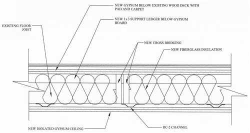
Resilient channel works as well on ceilings as it does on walls, although I would recommend the use of the double-leg system due its capacity to carry a greater load than the single-leg system. Refer to the manufacturer’s recommendations for the maximum spacing and load for their particular product.
RISC-1 clips and hat sections can also be used on ceilings with the same results you get on walls. The advantage to using this system is that the drywall ceiling can run directly to the perimeter of the existing wall assembly. This solves issues with weak isolation points at that location, as well as creating a good seal for fireblocking. The disadvantage is lower isolation than totally isolated structural assemblies. Figure 4.22 is a typical installation using single-leg resilient channel on a ceiling.
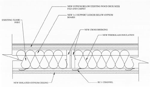
Figure 4.23 is a double-leg resilient channel, and Figure 4.24 shows the conditions with RISC-1 clip assemblies.
Standard suspended ceilings, utilizing T-tracks with L-channels at the ceiling’s edges and laying in tiles, are not of any use for the purpose of serious isolation and should not be considered.
A semi-independent frame ceiling would be supported by your interior walls at the edges—with interior supports added to transfer some of the ceiling load back to the existing structure above. This would generally be the case where you could not install a member large enough to support the entire load with a joist spanning the width of your room. This can be accomplished, with you still maintaining a good degree of isolation, through the use of isolation hangers carried by the structure above.
Once again, as with floating slab construction, it is very important that you take into consideration the weight being carried by the individual hangers in order to make certain you load them up enough to engage the spring action of the isolator. Too much or too little load, and they will transfer sound energy through to the structure above.
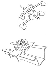
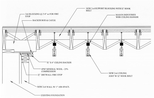
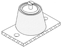
Figure 4.25 is a picture of a Mason Industries hanger made for this purpose. It’s their WHR ceiling hanger.
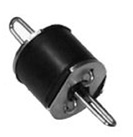
Figure 4.26 is a section through a deck (with the joist running lengthwise) that shows this hanger in use on a semi-independent ceiling assembly.
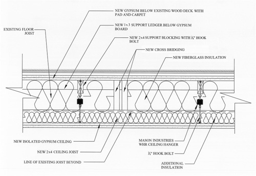
Figure 4.27 is a view of this with a section running through the new ceiling joist.
A downside to using this approach is (again) the load that it imposes on the existing structure, which will reduce the amount of mass you can add to the bottom of the deck above.
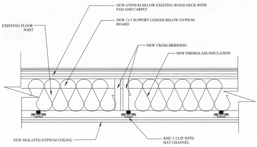
Independently framed ceiling assemblies carried by your new interior studio walls are the best isolation you can achieve. One of the big advantages of this system is the fact that it will impose no weight to the existing structure, so you can add that much more mass to that structure to help with isolation. Figure 4.28 is an independently framed ceiling below an existing structure. Note how the new ceiling joist is offset above the bottom of the existing floor joist. This is the reason I suggest you use cross-bridging rather than a solid block bridging for the existing assembly. Although solid bridging (a block made from the same dimensional material as the existing floor joist) creates a deck that is more solid than the cross-bridging, it will not allow the new joist to enter the pocket of the existing joist.
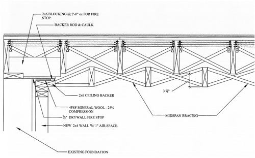
In the case of Figure 4.28 (with 2x10 existing joist and new 2x6 ceiling joist), the difference would be losing 3 ⅝″ of ceiling height versus 5” with solid bridging. In tight spaces, such as existing basements, that extra few inches could make a world of difference in a room.
Take a moment and focus on the firestop detail in Figure 4.28. It’s important that you take care during construction to create assemblies that will not create chimney effects in case of fire. The ½″ drywall creates an effective firestop, yet maintains (as detailed) isolation between the two structures. Without this type of care taken during the construction process, a fire within the wall cavity could completely envelope the room in fire before you ever knew it was there. The creation of fire compartments within wall and ceiling cavities will provide a safe environment for you in case of an emergency.
There are a series of isolation products manufactured by Mason Industries. We’ll take a look at how to use them properly in Chapter 10.
Figure 4.29 shows NPS Neoprene Partition Supports. Just as you can float slabs and ceilings, you can also float walls. These partition supports provide isolation from the existing slab to minimize slab transmissions into the wall structure.
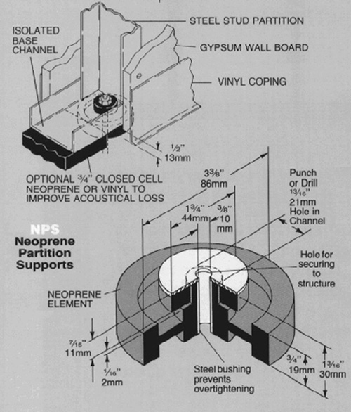
Figure 4.30 shows DNSB wall braces. Sway braces prevent buckling or overturning of tall or extremely long walls.
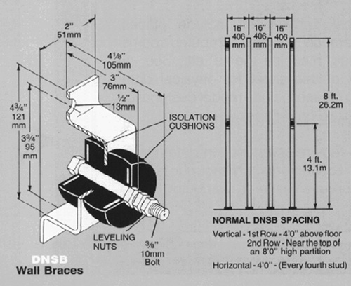
Figure 4.31 shows WIC and WCL sway braces. These products are ideal for lateral wall support where needed, while still maintaining isolation from the existing structure.

In a constrained layer damping (CLD) system, a damping material is sandwiched between two other (usually stiff/rigid) materials. Damping occurs when the viscoelastic center of the “sandwich” is sheared (see Figure 4.32).
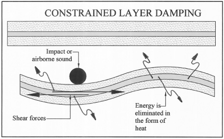
When bent, shear forces pull and stretch the damping material. Energy is lost when the damping material is sheared. The vibration energy is not isolated, but rather it′s destroyed and converted to heat at a rate defined by the efficiency of the damping material in any given system.
This is totally different than using an adhesive to glue multiple pieces of material together. When two pieces of drywall (for example) are joined together through the use of conventional construction adhesives, they bond, forming (essentially) one thicker piece of material. The effective isolation created from this type of assembly is less (as a whole) than the sum of the individual sheet themselves.
Thus, by gluing sheets together (using standard adhesives), you decrease isolation.
But with damping systems, the bonding actions that take place with conventional adhesives never occur, and the isolation is (potentially) greater than the sum of the two sheets themselves.
There are a large number of damping systems on the market: sheet-loaded vinyl, polymeric materials incorporating mineral fillers, etc. But the only one that has caught my attention (providing not only greater isolation at low frequencies than standard drywall, while maintaining a cost performance that’s reasonable) is a product called Green Glue, which is manufactured by the Green Glue Company.
Is Green Glue more effective than just adding additional sheets of drywall? Well, if you remember Mass Law—each doubling of mass theoretically adds 6dB of additional isolation. But Mass Law stops at the drywall itself (in this case), so when it comes to a complete wall assembly, reality is closer to 4– 5dB. So if you have two sheets on each side of a wall, the next step is four sheets on each side for an averaged increase of a maximum of 5dB.
Figure 4.33 is a comparison of four wall assemblies, three of which were tested at Orfield Labs[3] for the Green Glue Company. The first is a simple single-stud wall with one layer of drywall on each side. The second is a single-stud wall with two layers of ⅝″ drywall on each side. The third is a single-stud wall with two layers of drywall on each side, with Green Glue sandwiched between the drywall on both sides. The fourth wall is an estimated performance for a single-stud wall with four layers of drywall on each side. Finally, at the bottom of the sheet, you see a chart line that shows you what Mass Law will gain you for each doubling of mass with this wall assembly, just for comparison’s sake.
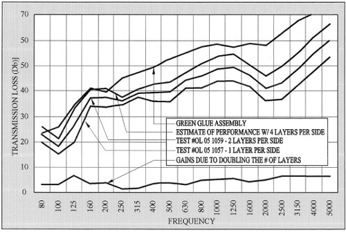
Note the increase in performance for the wall with only two layers of drywall on each face by adding Green Glue to the assembly. Note as well the superior performance of that wall to the wall with four layers of drywall and no Green Glue. Although they are close in the 125 to 200Hz range, the Green Glue wall is far superior over 200Hz, as well as around 100Hz.
This is a product well worth considering if weight is a consideration in your structural analysis. It’s a very effective means of increasing the ceiling floor assembly without the added weight that you have with strictly a mass approach to your construction.
Whether or not you need this product is something you have to decide. This decision (like everything else) should be based on a careful analysis of needs (meaning how much isolation you really need to provide). If you are a drummer playing light jazz with a set of 7b drumsticks, you can probably handle your isolation needs with some decent isolated construction and a couple of layers of drywall. If (on the other hand) you have a band playing heavy metal at full volume, that would not come even close to providing any reasonable amount of isolation.
Only you can make that determination.
A system that I have employed with some success since the first edition of this book is a floating wall/ceiling system with a modified floating deck assembly.
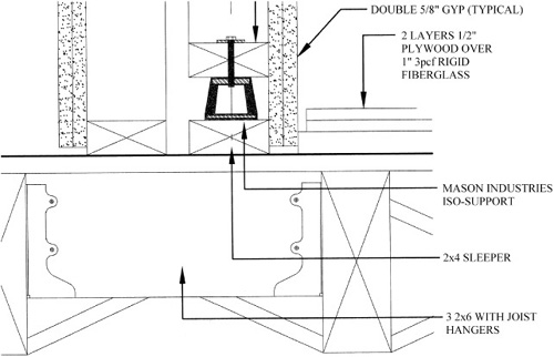
The walls are constructed using Mason Industries ND Isolators (see Figure 4.34). After constructing your walls, you can add an isolating floor assembly using 1″ or 2″ of 703 rigid insulation with two layers of plywood covering that (your new plywood deck).
Although this is not a true floating deck, it does have its benefits. A big plus for this system is that is creates a very effective barrier to impact sound transmission to the room below your floor.
Another benefit is that it does not create a drum head, which is due to the plywood resting completely on a bed of rigid insulation, which effectively damps the surface.
Figure 4.35 shows a section through this assembly. We will examine how to detail and calculate for these supports in Chapter 10.