
CONTENTS
15.2.1 Review of Criminisi’s Algorithm
15.2.2 Problems with Image Inpainting Algorithm
15.3 The Proposed Image Inpainting Algorithm
15.3.1 Structure Priority Value
15.3.2 Dynamic Searching Range
15.4.1 Analysis of the Influence of the Shape of Target Region
15.4.2 Inpainting Results of Natural Images
15.4.3 Evaluation of Man-Made Images
The growth of digital images has led to an increasing need for image editing techniques. Image inpainting is one such authoring technique for repairing or adjusting on-hand images. Image inpainting focuses on automatically repairing the missed regions of an image in a visually plausible way. Original image inpainting algorithms have been presented to repair small missed or damaged areas (Bertalmio et al., 2000; Ballester et al., 2001; Telea, 2004), such as speckles, scratches, and text in image. The texture synpaper method (Efros and Leung, 1999; Drori et al., 2003.) can effectively repair the damaged image, but is more suitable for repairing the image single or simple texture. Since texture synpaper is based on a known texture sample, it is inappropriate for repairing images involving complex and unknown textures.
The most important issue for image inpainting of large missing area is to determine the structure information of these areas, and repair them seamlessly from existing surrounding information. Previous studies address this issue by solving two problems: analyzing the structural information from the remainder image (e.g., the contour and shape) and keeping the texture information in order to reduce the visual artifact of repaired image. Ballester et al. (2001) and Bertalmio et al. (2001) adopted a method that utilizes partial differential equations to propagate the structure of the missing area, but which produces a vague repaired result if the missed area is large. Jia and Tang (2003) addressed color and texture segmentation, applying the tensor voting algorithm to segment the image for propagating the structure of the missed area. The resulting structure is used to identify the searching range and the filling order. Since two parameters control the smoothness of the propagation curve, the algorithm can repair not only linear structures but also nonlinear structures in a missed area. However, it takes a long time for color segmentation and structure propagation. To reduce the time taken, the missed area can be filled manually according to the structure drawn. Wang et al. (2005) and Rares et al. (2005) presented similar algorithms to Jia and Tang (2003). Wang et al. (2005) adopted the constrained texture synthesis (Wang et al., 2004) to analyze the texture distribution, and then defined the searching range for the filling image. Due to the visual artifacts in the repaired image, an algorithm was presented to detect the artifacts and refill these regions again. Rares et al. (2005) proposed an algorithm that first extracts the edges or corners of an image, then defines an order for edge permutation. However, the algorithm is only suitable for some structure distribution, and produces a blur effect in the repaired image.
To repair an image effectively without apparent artifacts, Criminisi et al. (2003), Criminisi et al. (2004) adopted the magnitude of the gradient and undamaged area of an image to define the filling order and searching direction for finding the best patches. The advantage of this algorithm is that it is very suitable for repairing linear structures in the missed area, and it smoothly connects the repaired region with the nearby undamaged region. However, the filling order is random and unreliable. Hence, further works (Cheng et al., 2005; Li et al., 2005; Nie et al., 2006; Shao et al., 2006) have been conducted to improve the result by redefining the filling order. In addition to the structure information, texture information is also an important factor for repairing images. Some studies focus on analyzing texture information (Bertalmio et al., 2003; Shao et al., 2006). Most related studies use an exemplar-based method to keep the texture information of an image. Shao et al. (2006) presented an algorithm to repair images based on the Poisson equation. The algorithm decomposes an image into structure and texture images, and assigned the weights for both images to compose a patch to fill in the missing region. Their method successfully keeps the texture information, but may produce blurred artifacts.
In this chapter, we will introduce a robust image inpainting algorithm to determine a new filling order based on the structure priority value. The algorithm can fill the missing area with more accurate structure information. Besides, the dynamic searching range is utilized to improve the efficiency of finding the best patches in the source region. The rest of this chapter is organized as follows. Section 15.2 describes the concept of image inpainting and the related problems. Section 15.3 presents the details of the proposed algorithm. Section 15.4 presents the experimental results and discussions. Finally, conclusions are drawn in Section 15.5.
The difficulty of repairing a large missing area is how to define the filling order and keep the structure information and texture information from the surrounding of the area. Criminisi et al. (2004) developed a very effective and popular algorithm that provides a good solution for this problem. However, the algorithm has some problems. This section reviews the algorithm and discusses the associated problems.
15.2.1 REVIEW OF CRIMINISI’s ALGORITHM
Criminisi’s algorithm is an isophote-driven image-sampling process. The filling order in the repairing process is determined by the gradient information of an exemplar. Figure 15.1 illustrates a single iteration in filling the target region centered at point p. An image I is divided into disjoint regions, the target region Ω and the source region Φ. The target region is the selection area that needs to be filled in, and the corresponding contour is denoted as δ Ω. An image excluding the target region and the contour of Ω is defined as the source region, that is, Φ = I – Ω. Ψp denotes a square patch centered at a point p, where p is located at δΩ.
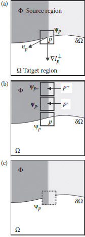
FIGURE 15.1 Illustration of a single iteration of Criminisi’s algorithm in filling the target region centered at point p. (a) Initial status. (b) Searching the best matching patch. (c) The result of iteration 1
A key part of the inpainting process is to determine the filling order for the target region. The priority value of each square patch Ψp∈ Ω is adopted to find the filling order for all unfilled pixels. The priority value P(p) is defined as the product of two terms:
(15.1) |
where C(p) and D(p) are called confidence term and data term, respectively. These terms are defined as follows:
(15.2) |
(15.3) |
where |Ψp| denotes the area of Ψpand α is a normalized parameter. For gray-level image, α is assigned to 255. In the initial step, the value of C(p) is set to be 0 if p ∈ Ω and 1 if p ∈ Φ. In Equation 15.3, np is the normal vector of the δΩ at point p, ∇ is denoted as a gradient operator, and ⊥ is an isophote (direction and intensity) orthogonal to the gradient. When all priority values of the patches along δΩ have been computed, the patch with the maximum priority value would be selected as the first one to be filled. Ifis with the maximum priority value after the filling order determination, the next step is to search for a patch around the source region that is most similar to according to the following equation:
(15.4) |
where the distance between two patches and is defined as the sum of squared differences (SSD) of the already repaired pixels in these two patches. After a patch has been filled, the confidence C(p) is updated as follows:
(15.5) |
In general, γ < 1, and the new C(p) inherits a certain portion of the value corresponding to the last C(p). Additionally, to reduce the time of finding best match patch, the search path will follow the isophote of point p. The filling process proceeds until all pixels in the target region have been filled.
15.2.2 PROBLEMS WITH IMAGE INPAINTING ALGORITHM
The priority P(p) contains two parameters, the data term D(p) and the confidence term C(p). The data term contains the gradient information and stores the structure part when the missed area is being filled. If the data term is a large value, then the linear structures are synthesized first. However, if the patch contains too few pixels of the source image, then the corresponding data term is not reliable. To avoid this mistake, the confidence term is added as a measurement of the reliable information around the pixel p. Using the two factors, the algorithm tries to retain not only the structure information of an image but also the texture information. The method indeed achieves good performance, but it still suffers from three problems.
1. The structure information may be broken by inappropriate values of C(p) and D(p). Assume there are two patches, Ψpand Ψq, and the algorithm needs to determine the first one to be filled. If the vectors of are the same, for example, (0,1), and the patch size is then the gradient and the confidence term of Ψp and Ψq, are Hence, the isophotes of Ψp and Ψq, are respectively. Assume that (xp,yp) = (4.5, 7), (xq, yq) = (8, 7), sp = 70, sq = 40, and n = 9.Then the priority value of Ψp is larger than that of Ψq, and so the patch Ψp will be filled first. However, in the case, the data value of Ψq is larger than that of Ψp. Experimental results indicate that once the confidence values are above a particular value, the patch with the larger data value should be chosen, even if it has the smaller priority value; otherwise, the filling process loses the structure information of the image. Thus, the confidence and data values should have different weighting factors to generate the priority value, but adequate weighting factors are hard to obtain.
2. The updating rule of the confidence term, that is, Equation 15.5, makes the priority value to decay to zero, and causes the patch selection to be random. If the inherited weight α is set between 0 and 1, then the confidence value decays as the iteration number of filling process increases. The value of C(p) approaches zero after a series of filling operations.
(15.6) |
Here, n denotes the iteration number of filling operation, and α ∈ (0,1). Once the confidence value drops below a small value, the priority value is dominated by the confidence value, and also drops to a small value, regardless of the data value of a patch. Cheng et al. (2005) also observed the same problem, which causes the filling process to fill the target region randomly. Therefore, the inpainting result does not properly represent the structure information. The dropping effect causes the random filling process to destroy the structure information. Figure 15.2a shows the distribution of the priority value during the filling process of an image. The priority is very small after a number of iterations due to the decay of the confidence value (Figure 15.2b). Figure 15.2c shows the corresponding data value distribution.
The above-mentioned problem still exists if the value of the inherited weight is increased to delay the confidence value dropping to zero, as long as the target region is large enough. An excessive inherited weight also forces the filling direction along some specific path, on the other hand, while a smaller weight enhances the impact of the dropping effect. Selecting an appropriate inherited weight is difficult, while an unsuitable weight would not retain the structure information effectively.
3. The searching range defined by the isophote is not so reliable. Criminisi defined the isophote as the searching hint to determine the best matched patch. The method works well if the texture around the patch is simple; however, the related gradient cannot be calculated accurately when a patch contains two or more materials or textures. The corresponding isophote then induces the wrong searching direction, and probably finds an unsuitable patch.
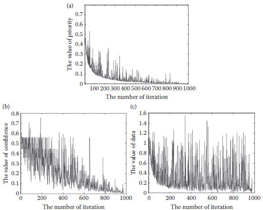
FIGURE 15.2 Illustration of the filling processing of an image. (a) The distribution of the priority value. (b) The distribution of the confidence value. (c) The distribution of the data value.
15.3 THE PROPOSED IMAGE INPAINTING ALGORITHM
The inpainting algorithm concerns two major issues: (1) appropriate filling order and (2) adequate searching range. The proposed inpainting algorithm defines the new parameter, structure priority value, which can efficiently keep the structure information of an image. Besides, it adopts the example-based method and dynamic searching range to maintain the texture information. Different from the algorithms of Criminisi et al. (2004) and Cheng et al. (2005), we do not need to adjust the parameters for the damaged images with a different scene, for example, the weights of the confidence and data terms, and can still keep the structure information effectively.
15.3.1 STRUCTURE PRIORITY VALUE
The notation adopted here is similar to that defined in Section 15.2.1. Figure 15.3 illustrates the meanings of the notation. If some region is removed, the removed region is denoted as target region Ω; the contour of the target region is represented as δΩ and the area excluding the target region is marked as source region (Φ = I − Ω).
The study adopts the edge ratio instead of the data value used in Criminisi’s algorithm, to preserve the structure information. The new term is denoted as the structure priority (SP) value, and is defined as follows:
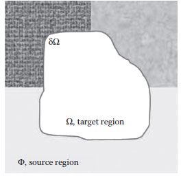
FIGURE 15.3 Notation diagram of our algorithm. The symbol Ω is the target region and its corresponding contour is denoted as δΩ.
(15.7) |
where C(p) is the confidence value that determines the reliability of the corresponding patch, and ER(p) denotes the edge value. The term ER(p) is defined as the ratio of edge points relative to the source region inside the patch, and the equation is as follows:
(15.8) |
(15.9) |
where e(q) denotes whether pixel p is an edge point. A higher SP indicates a higher priority for filling the corresponding patch. This definition of filling order can avoid the disadvantage of the previous algorithms (Criminisi et al., 2004; Li et al., 2005; Nie et al., 2006). Although the priority function in (Cheng et al., 2005; Li et al., 2005; Nie et al., 2006; Shao et al., 2006) is modified by combining the confidence term and the data term, the confidence term still has a negative impact on the determination of the priority values. Moreover, the confidence value is computed at each filling iteration rather than the inherited rule (Equation 15.5), thus avoiding the second disadvantage in the previous chapter. For instance, in Figure 15.4a–c, the patch Ψpis filled in the first iteration, and the confidence value is then recalculated by Equation 15.2. If C(p′) < C(q), then Ψq is filled in the second iteration. However, it still cannot reduce the confidence term impact on the priority value. The influence of the confidence term on the priority value is still not lowered even if more structure information is kept.
The definition of the filling order in our algorithm does not majorly depend on the confidence term. In our experiments, we observed that the C(p) of most selected patches are higher than 0.5. The dropping effect does not occur in the filling process. Figure 15.5 demonstrates one example of the filling process. Figure 15.5a is the original image, and 96% of the values of C(p) are higher than 0.5 during repairing process (Figure 15.5b). Figure 15.5c is the corresponding ER distribution.
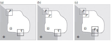
FIGURE 15.4 The filling process. (a) Initial status. (b) The result of iteration 1. (c) The result of iteration 2.
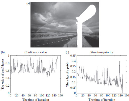
FIGURE 15.5 Illustration of the filling processing of an image. (a) Input image. (b) The distribution of the confidence value. (c) The distribution of the edge ratio.
Calculating the ER(p) of δΩ involves deriving the edge map of the corresponding image using the Canny edge detector. The benefit of the Canny edge detector is that it does not blur the edge in image like the Gaussian filter, and therefore produces accurate gradient information for the input image. Moreover, Canny edge can produce continuous edges, unlike some other detectors, for example, Sobel and Laplacian.
15.3.2 DYNAMIC SEARCHING RANGE
Besides the filling order, the searching range is another important factor which influences the result of the repaired image. The determination of search range also affects the time taken to perform the inpainting process.
A straightforward way to search the best match is to regard the entire image as the searching range; however, this approach takes a long time, and an excessively large search range creates many errors. One fast and easy way to obtain the best matching patch is to define the minimum boundary rectangle (MBR) of the target region, and expand the area of MBR to obtain the searching range. Since the shapes of the target region may be different, for example, a mixture of convex or concave shapes, expanding MBR with a fixed width, does not work. Instead, the searching range is dynamically adjusted based on the shape of the target region, checking whether the ratio between the target region and the source region is beyond a predefined bound. The expansion process of the searching range is described as follows:
(15.10) |
While
where MBR(I) denotes the MBR of the target region in an image I, E_MBRt is the expansion of MBR, and the initial state is set to MBR(I). The function of Expand(•) is to expand E_MBR by one pixel width. E_MBR is expanded until the ratio of the pixels belonging to the target and source regions in the E_MBR is higher than β. A typical suitable value of β is 1.5. Figure 15.6a shows the searching range of a convex target region and Figure 15.6b illustrates that of a concave target region. The expansion of MBR for a concave shape is normally smaller than that for a convex shape, since the initial MBR already includes enough of the source region.
In addition to the reduction of the searching time compared to the full search, the proposed algorithm can also avoid the drawback of Criminisi’s algorithm. Criminisi’s algorithm only searches along the particular direction (isophote) of the image, but introduces an error when the patch contains complex textures. Additionally, the searching range needs to exclude the area filled in previous filling iterations, because the patch found in the current iteration may have been filled patch in a previous iteration. Filling such a patch may result in appearance artifacts in the repaired image, as shown in Figure 15.7. If the car on the left side of Figure 15.7a is the target region, then Figure 15.7b shows the inpainting result when the searching range includes the filled area. The area marked by the red rectangle is the artifact, and the filled area refers to the same patch. However, the artifact disappears if the searching range is limited to the original source region (Figure 15.7c).
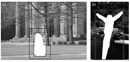
FIGURE 15.6 Dynamic searching range. (a) Target region of convex shape. (b) Target region of concave shape. The searching range is the area between the red and blue rectangles.
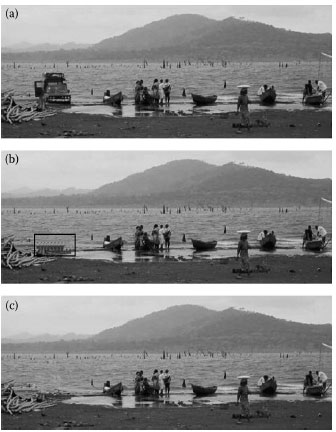
FIGURE 15.7 Reduce the artifact in the repaired image. (a) Original image: the car is set as the target region. (b) Inpainting result with artifact in the red rectangle: the searching range includes the previous filled area. (c) Inpainting result: the searching range excludes the previous filled area.
This section evaluates and discusses the proposed algorithm in three subsections. Section 15.4.1 demonstrates the robustness under the different shapes of target regions. Section 15.4.2 evaluates the performance of the process on natural images. The experimental results are examined to determine whether the filling results can keep the structure information. Section 15.4.3 compares the results between the proposed method and the texture synthesis method. Section 15.4.4 describes the processed results of the man-made images.
15.4.1 ANALYSIS OF the INFLUENCE OF THE SHAPE OF TARGET REGION
To compare the performance of different image inpainting algorithms, Figure 15.8 illustrates several inpainting results where the jump man is removed. Figure 15.8a is the original image and Figure 15.8b shows the result of applying Criminisi’s algorithm. Figure 15.8c shows the result of applying Wang et al. (2005) without artifact detection, where the eave structure contains a crack. Figure 15.8d illustrates the result of artifact detection and refilling. However, the eaves in Figure 15.8d are still sunken. Figure 15.8e shows the result of applying Shao et al. (2006).
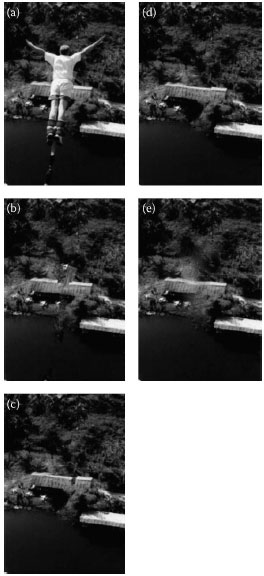
FIGURE 15.8 Example of repairing jump man. (a) Original image. (b) The result of Criminisi et al. (2004). (Adapted from Criminisi, A., Pérez, P., and Toyama, K., IEEE Transactions on Image Processing, 13(9), 1200–1212, 2004.) (c) The result of Wang et al. (2005) without artifact detection. (d) The result of Wang et al. (2005) with artifact detection. (Adapted from Wang, J.-F., Hsu, H.-J., and Liao, S.-C. IEEE International Conference on Image Processing, vol. 2, pp. 73–76, September 2005.) (e) The result of Shao et al. (2006). (Adapted from Shao, X., Liu, Z., and Li, H., IEEE International Conference on Document Image Analysis for Libraries, pp. 368–372, April 2006.)
Figure 15.9 shows the inpainting results for the jump man image, demonstrating that the proposed algorithm is robust to a change in the target region. The size and shape of the target region significantly affect the inpainting result since the reference source image is different after the target region is changed. Figure 15.9 indicates that the proposed approach can maintain good quality even if the target region varies. The left column of Figure 15.9 shows the image for a different target region; the middle column shows the results of the proposed method; and the right column displays those of the Criminisi’s algorithm for the same target region. The resulting images indicate that the proposed algorithm can accurately reconstruct the eaves with the natural scene. Although the result in the fourth row is not as good as that of the upper three, the eaves of the results of Criminisi et al. (2004) are distorted.
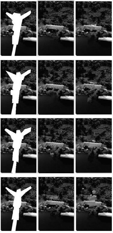
FIGURE 15.9 The repaired jump man images for different target regions. The left column shows four removed regions; the results of the proposed algorithm are shown in the middle column; and the right column presents the results using Criminisi et al. (2004) algorithm. (Adapted from Criminisi, A., Pérez, P., and Toyama, K., IEEE Transactions on Image Processing, 13(9), 1200–1212, 2004.)
15.4.2 INPAINTING RESULTS OF NATURAL IMAGES
The section presents the results of several different natural images, and checks whether the distribution of the confidence value is almost beyond a level. The differences between the proposed approach and other inpainting algorithms are also described.
Figure 15.10 shows the result of repairing a tiny area, such as the leg of the dog. Figure 15.10a shows an image of the riverside and Figure 15.10b shows the target region, where the sign is removed from the picture. Figure 15.10c illustrates the result using Criminisi’s algorithm and Figure 15.10d is the result of the proposed algorithm. The repaired leg of the dog in Figure 15.10d is more natural and smoother than that in Figure 15.10c. Figure 15.10e and f shows the corresponding distributions of the confidence value and the edge ratio. Notably, almost all the confidence values are greater than 0.5, and the confidence values do not have the dropping effect as in the previous method.
Cheng et al. (2005) adopts a good approach, which uses the linear combination to generate the confidence and data values for calculating the structure value. The method assigns different weights to these two values based on the structure or texture for each image, but requires manual trial and error to determine the appropriate weights. Figure 15.11b andc shows the results with different weighting policies. Figure 15.11d illustrates the result of our approach, where the inner and outer structure of the sand tower is more complete, and we do not need to be assigned the weights for each input image. Figure 15.11e shows the distribution of confidence values during the process, which remains above 0.5 during almost the entire iteration process. Figure 15.11f is the corresponding distribution of edge ratios.
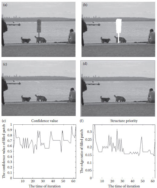
FIGURE 15.10 Repair the tiny area of an image. (a) Original image. (b) The target region is marked with white. (c) The result of Criminisi et al. (2004). (d) The result of the proposed algorithm. (e) The distribution of the confidence value. (f) The distribution of the edge ratio where the iteration number is 62. (Adapted from Criminisi, A., Pérez, P., and Toyama, K., IEEE Transactions on Image Processing, 13(9), 1200–1212, 2004.
The algorithm of Shao et al. (2006) applies the technique of texture analysis to fill the image, as indicated inFigures 15.12b and 15.13b. Although the proposed algorithm does not analyze the texture information before the inpainting process, the repaired texture of Figures 15.12c and 15.13c is as natural as the results of Shao et al. (2006).
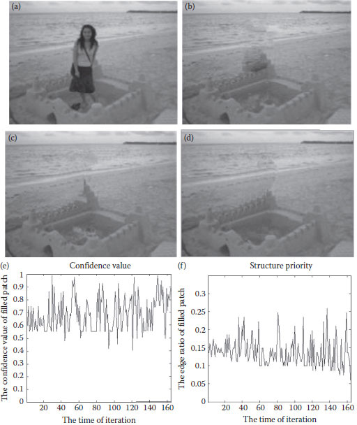
FIGURE 15.11 Comparison between the proposed algorithm and Cheng et al. (2005). (a) Original image. (b) and (c) Reconstruction with different weighting factors of Cheng et al. (2005). (d) Result of the proposed algorithm, where the texture and structure information of an image is successfully kept. (e) The distribution of the confidence value. (f) The distribution of the edge ratio where the iteration number is 165. (Adapted from Cheng, W.-H., et al., IEEE International Conference on Computer Graphics, Imaging and Vision, pp. 26–29, July, 2005.)
Figure 15.14a is an image of a girl standing before a wall and a small garden. The girl was selected to be removed, and the target region covered four materials from top to down: rock wall, grass, cement wall, and ground (Figure 15.14b). Figure 15.14c shows the inpainting result. The proposed approach successfully rebuilt the rock wall–grass, grass–cement wall, and cement wall–ground boundary areas. Figure 15.14d and e illustrates the distributions of the confidence values and edge ratios.
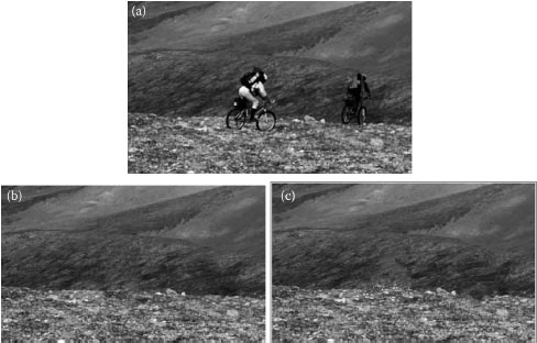
FIGURE 15.12 The removed region is the bicycle men. (a) Original image. (b) The result of Shao et al. (2006). (c) The result of the proposed algorithm. (Adapted from Shao, X., Liu, Z., and Li, H., IEEE International Conference on Document Image Analysis for Libraries, pp. 368–372, April 2006.)
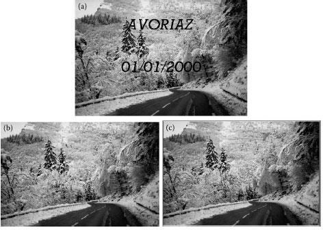
FIGURE 15.13 Remove texts of the image. (a) Original image. (b) The result of Bornard et al. (2002). (c) The result of the proposed algorithm. (Adapted from Bornard, R. et al., Missing date correction in still images and image sequences, In Proceedings of the Tenth ACM International Conference on Multimedia, December 2002.)
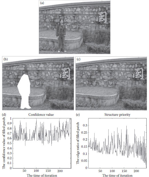
FIGURE 15.14 An example of keeping the structure information of an image. (a) Original image. (b) The target region. (c) The result of the proposed algorithm. (d) The distribution of the confidence values. (e) The distribution of the edge ratio.
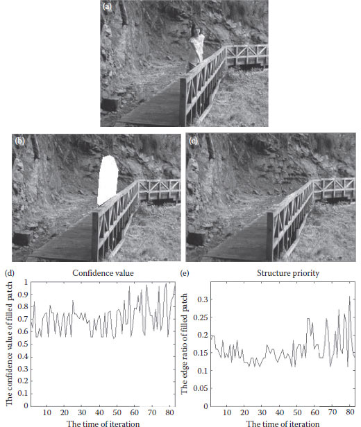
FIGURE 15.15 Remove the person of an image. (a) Original image. (b) The target region. c) The result of the proposed algorithm. (d) The distribution of the confidence value. (e) The distribution of the edge ratio.
Figure 15.15a shows a girl standing on a bridge, and a rock in the background. The girl was removed and the target region is shown in Figure 15.15b. Figure 15.15c shows the inpainting result, which indicates that the background of grass and rock was successfully reconstructed. The confidence values remained above 0.5 during the iteration process (see Figure 15.15d). Figure 15.15e illustrates the distribution of the edge ratio.
15.4.3 EVALUATION OF MAN-MADE IMAGES
Finally, the performance on the man-made images was evaluated, as shown in Figures 15.16a and 15.17a. The key point is to observe whether the boundary between adjacent textures can be restored smoothly.Figures 15.16b and 15.17b illustrate the removed regions, and Figures 15.16c and 15.17c show the reconstructed images. The texture elements and the boundaries were successfully rebuilt in both cases. Figure 15.16d ande illustrate the corresponding distributions of the confidence value and the edge ratio.
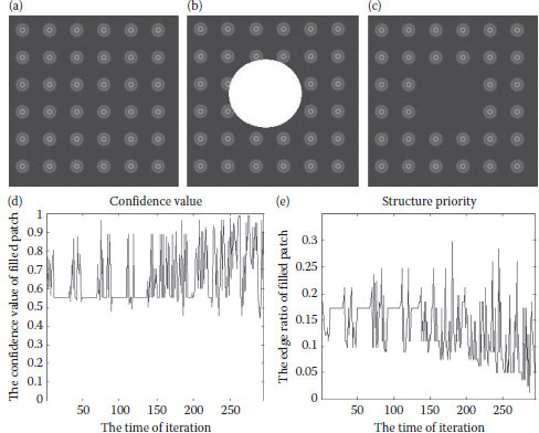
FIGURE 15.16 Circle dot image.(a) Original image.(b) The target region. (c) The result of the proposed algorithm. (d) The distribution of confidence value. (e) The distribution of the edge ratio where the iteration number is 296.

FIGURE 15.17 Single-texture images. (a) Original image. (b) Target region. (c) Inpainting result.
This work presents a new method for determining the filling order of inpainting. The proposed approach is robust in filling missing or removed regions of an image. It also performs well for different kinds of man-made images and natural images, regardless of whether their textures are simple or complex. Experimental results demonstrate that the proposed algorithm can fill the damaged image with visually plausible backgrounds.
Ballester, C., Caselles, V., Verdera, J., Bertalmio, M., and Sapir, G., A variational model for filling-in gray level and color images, In Eighth IEEE International Conference on Computer Vision, vol. 1, pp. 10–16, July 2001.
Bertalmio, M., Bertozzi, A. L., and Sapiro, G., Navier-Stokes, Fluid dynamics, and image and video inpainting, In Proceedings of IEEE Conference on Computer Vision and Pattern Recognition, vol. 1, pp. 355–362, December 2001.
Bertalmio, M., Sapiro, G., Caselles, V., and Ballester, C., Image inpainting, In Proceeding of ACM Conference on Computer Graphics (SIGGRAPH), pp. 417–424, July 2000.
Bertalmio, M., Vese, L., Sapiro, G., and Osher, S., Simultaneous structure and texture image inpainting, IEEE Transactions on Image Processing, 12(8), 882–889, 2003.
Bornard, R., Lecan, E., Laborelli, L., and Chenot, J.H., Missing date correction in still images and image sequences, In Proceedings of the Tenth ACM International Conference on Multimedia, France December 2003.
Cheng, W.-H., Hsieh, C.-W., Lin, S.-K., Wang, C.-W., and Wu, J.-L., Robust algorithm for examplar based image inpainting, In IEEE International Conference on Computer Graphics, Imaging and Vision, pp. 26–29, July 2005.
Criminisi, A., Pérez, p., and Toyama, K., Object removal by exemplar-based inpainting, In IEEE Conference on Computer Vision and Pattern Recognition, vol. 2, pp. 721–728, June 2003.
Criminisi, A., Pérez, p., and Toyama, K., Region filling and object removal by exemplar-based image inpainting, IEEE Transactions on Image Processing, 13(9), pp. 1200–1212, 2004.
Drori, I., Cohen-Or, D., and Yeshurun, H., Fragment-based image completion, ACM Transactions on Graphics, 22(3), 2003.
Efros, A. A.Leung, T. K., FTexture synpaper by non-parametric sampling, In The Proceedings of the Seventh IEEE International Conference on Computer Vision, vol. 2, pp. 1033–1038, September 1999.
Jia, J., and Tang, C.-K., Image repairing: Robust image synpaper by adaptive ND tensor voting, In IEEE Computer Society Conference on Computer Vision and Pattern Recognition, vol. 1, pp. 643–650, June 2003.
Li, B.-R., Qi, Y., and Shen, X.-K., An image inpainting method, In IEEE Ninth International Conference on Computer Aided Design and Computer Graphics, pp. 531–536, December 2005.
Nie, D., Ma, L., and Xiao, S., Similarity based image inpainting method, In Proceedings of IEEE International Conference on Multi-Media Modelling, January 2006.
Rares, A., Reinders, J., Marcel, T., and Biemond, J., Edge-based image restoration, IEEE Transactions on Image Processing, 14(10), 1454–1468, 2005.
Shao, X., Liu, Z., and Li, H., An image inpainting approach based on Poisson equation, IEEE International Conference on Document Image Analysis for Libraries, pp. 368–372, 2006.
Telea, A., An image inpainting technique based on the fast marching method, Journal of Graphics Tools, 9(1), 25–36, 2004.
Wang, J.-F., Hsu, H.-J., and Liao, S.-C., A novel framework for object removal from digital photograph, In IEEE International Conference on Image Processing, Vol. 2, pp. 73–76, September 2005.
Wang, J.-F., Hsu, H.-J., and Wang, H.-M., Constrained texture synpaper by scalabel sub-patch algorithm, In IEEE International Conference on Multimedia and Expo, Vol. 1, pp. 635–638, June 2004.