

CUT AND COPY
SPLIT AN OBJECT WITH MESHMIXER

PROJECTS IN KIT
Alexandre Kournwsky is a young, ambitious industrial designer. The year he obtained his diploma from ENSCI – Les Ateliers, a renowned design school in Paris, he conceived Meïso, a relaxation center dedicated entirely to flotation and meditation. To carry out his project, the young entrepreneur had to first build a flotation capsule prototype, a sort of cocoon partially filled with water enriched with magnesium salt. He first considered thermoforming a large plastic sheet on a mold made of CNC-milled medium-density fiberboard (MDF) panels, but the tooling and manufacturing costs were exorbitant. So, he devised a technique using of a small 3D printer to make the mold brick by brick. The 3D model of the original mold was thus split into 450 parts, which he printed one by one on his MakerBot Replicator 2. It took three months to make all these bricks. Once he finished, the blocks were glued together, like a monumental 3D puzzle. Assisted by his friend and partner, Maïté, he used a mixture made from hot glue sticks as mortar for the construction of the large PLA igloo. Once it was assembled, several days of finishing with car mastic and sandpaper were essential before obtaining the smooth and even surface of the mold shown on the facing page.
What is probably the largest mold in history to be made on a personal 3D printer was used to make a first prototype of the cocoon in fiberglass. The first brick of the Meïso company.
Alexandre Kournwsky’s project proves that 3D printing has no limits for whoever offers their time to make their dreams come true.

Building the mold
By: Alexandre Kournwsky
3D printed on: Replicator 2
Source: Meïso
© Alexandre Kournwsky
Meïso’s mold finished
By: Alexandre Kournwsky
3D printed on: Replicator 2
Source: Meïso
© Alexandre Kournwsky
Architecture model
By: Alexandre Kournwsky
3D printed on: Replicator 2
Source: Meïso
© Samuel N. Bernier
SPLIT AN OBJECT WITH NETFABB
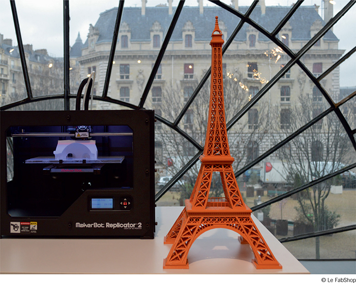
Sometimes the object we want to make is too wide or too tall for our 3D printer. In this case, one trick is to split the volume into several components to be made separately, then assembled. When you create the 3D file, it’s best you make these cuts directly in the software as you make the design. If you can’t do that, it’s possible to split large 3D objects using the Netfabb Basic and Meshmixer software. This trick also works when you want to print a geometrically complex part without support material or when you want to create a flat surface on an object whose base is not. Here’s how to do it:
Before beginning this exercise, download the Eiffel Tower from user B9Creations on Thingiverse:
http://www.thingiverse.com/thing:22051
This tutorial shows how to change the scale and split a file found on the Internet in order to make it into a format exceeding the size of the 3D printer.
After retrieving the Eiffel Tower model, open it in Netfabb Basic. The original object is 120.95 mm tall, which is too small to be printed in detail on most FDM/FFF 3D printers. We’ll multiply its size by about five times to obtain a 60 cm tall tower, which is four times the maximum height of a MakerBot Replicator 2.
In the toolbar, select the “Scale” icon, represented by a gray sphere with two arrows, one vertical, the other horizontal. This opens the Scale Parts window. In the “Parameters” section of the window, go to the line indicating “Target size” and change the Z value to 600 (the units are in millimeters). Then, click “Scale.” The model will automatically get bigger giving the impression that you’ve zoomed into the center of the part. Spin the scroll wheel on your mouse towards you for an overall view of the part again.

To be precise during the next steps, it’s best you replace the isometric view of the part with a simple front view. For this, select the “Front” icon in the toolbar.

You can now begin to divide the Tower. On the bottom right of the interface, you will find a gray window called “Cuts.” Set the Z-axis slider to 279 mm and leave it in the “Cut all parts” mode. Click on the “Execute cut” button. A new window will open. Click on “Cut” again.
You will see a new component appear in the “Parts” window on the top left of the screen.

Now repeat the cut function at the following heights: 140, 0, -29, -32, -229.
You should then have seven groups, but three of them are still too big for a Replicator: the first level, the feet of the Tower and its bases. Click each of these two volumes while holding down the shift key. The area should be colored green while the rest remains gray.
In the “Cut” function, move the X slider to any value and then back to zero, then switch the cut mode to “Cut only selected parts.”. Execute the cuts. You can repeat the step on Y with the bases and feet selected.

Your model now contains twelve volumes, but you only need to save seven of them under the STL format, as several of them are symmetrical and identical.

Upon exporting, accept the “Optimize” option suggested by Netfabb. This function will automatically resolve any conflicts generated during the previous step.


The parts, once printed, can be assembled with Epoxy glue.
You can download the split files on Thingiverse to compare your result:
http://www.thingiverse.com/thing:399769
The parts available on Thingiverse are positioned so as to optimize printing times and to eliminate the need of support materials or rafts.
The technique shown here to create a 60 cm Eiffel Tower can be used for a multitude of other applications. It makes the creation of objects in various colors and materials easier, allows you to optimize the printing direction and makes the production of objects sized much larger than the volume of the machine.
SPLIT AN OBJECT WITH MESHMIXER
When you use a FDM/FFF 3D printer, uneven and organic volumes are often problematic, as their lack of a flat surface requires support structures. In certain cases, when it doesn’t affect the design of the object, you can artificially create a flat surface by creating a material removal in relation to a surface. Here’s how to do it with Meshmixer:
Open Meshmixer and select “Import Sphere” in the central window or in the “File” tab.


A generic sphere will automatically import. In the toolbar on the left, choose the “Edit” function, represented by a gray sphere strewn with black triangles. Select the “Plane Cut” function.” A netting will appear, transforming half of your sphere into a phantom area. If you need to change the orientation of the plane cut, just drag your cursor onto the green rotation axis and slowly spin the cutting plane using the ruler of the dial that appears. Drag your mouse to the ruler as you rotate it to snap to 5 degree increments. To move the plane up and down, select the small blue arrow of the vertical axis (Z), then drag the plane to the desired height. Make sure the large blue arrow is oriented towards the face you want to remove. Change the orientation by clicking on it.


When you make the cut, the hole will automatically close up as long as the perimeter of the cutting area is even and the “Fill” mode of the “Plane Cut” window is set on “DelRefine”or “Delaunay”. (Changing the cutting style of “Cut” to “Slice Groups” allows you to split the mesh into different shells. To be able to select them separately, you will have to open the “Object Browser” and use the “Separate Shells” tool in “Edit”.) Click “Accept” in the gray window to confirm your choice.