
This is probably the most important chapter for you if you have never played with hardware before. In this chapter, we have a look at how we can understand an IoT device’s hardware from a security perspective for both internal and external analysis. The device, as we have seen in the earlier chapters, is one of the key components in any IoT product. It is the device component that can help reveal many secrets about the device to us, which we can also see later in this chapter.
Extracting firmware from the real-world IoT device.
Gaining root shell on the device to gain unrestricted access.
Performing live debugging to bypass security protections and restrictions.
Writing new firmware to the device.
Extending the device’s functionality.
In some cases, opening a device might lead to the device not working properly (due to physical tamperproofing) or you not being able to reassmble it. That is why, whenever you are performing an IoT device pentest, you should always ask for two (or more) sets of devices from the client so that you can perform physical security assessments on one of them and the rest of the vulnerability tests on the other.
If you have never opened hardware before, exercise special caution as you work through the procedures in this chapter so you do not hurt yourself. Always be gentle and figure out a way to open the device carefully so that you can put it back again in one piece after the analysis. Now, let’s get started.
External Inspection
What and how many buttons are present.
External interfacing options: Ethernet port, SD card slot, and more.
What kind of display the device has.
Power and voltage requirements for the device.
If the device carries any certifications and what they mean.
Any FCC ID labels on the back.
What kind of screws the device uses.
If the device looks like other devices with similar functionalities that you have seen in the market (maybe it’s just a rebranded model).
And so on (you get the idea!).
This initial analysis will give you a better understanding of the overall device and how it functions, and at the same time help you understand some inner details of the device.
Before you even open the device, there are a couple of things you can do just by performing this initial analysis. The initial analysis typically involves a visual inspection of the device and a review of other sources of information about the device. This step also involves using the device and figuring out what its normal functionality is. Once you determine the normal functionality of the device, you will be able to come up with target approaches to subvert the device’s functionality.
Working with a Real Device
Let’s take a sample device and start looking at it as just described. In this case, the device is a navigation system and the model is Navman N40i.
- 1.
It runs Windows CE 5.0.
- 2.
It has a 1.3 MP camera.
- 3.
It provides five hours of battery backup.
- 4.
It has a 400 MHz Samsung 2400.
- 5.
It has 64 MB of SDRAM.
- 6.
It has 256 MB ROM.
- 7.
It contains a SiRF STAR II GPS chip.
This useful information will be helpful if we later decide to find vulnerabilities in the Navman system. This quick example illustrates how to approach your device once you get it and the initial analysis that you should perform.
Finding Input and Output Ports
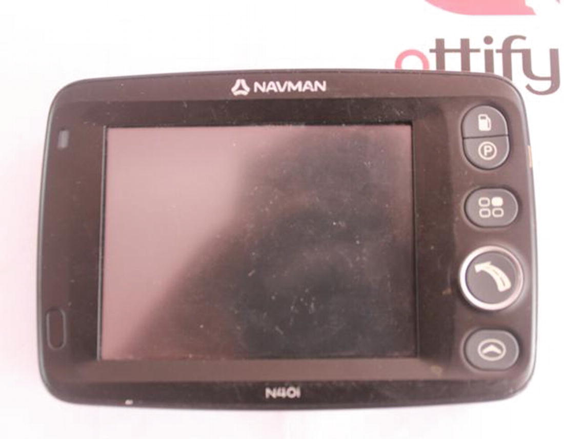
An emedded device, in this case a Navman N40i

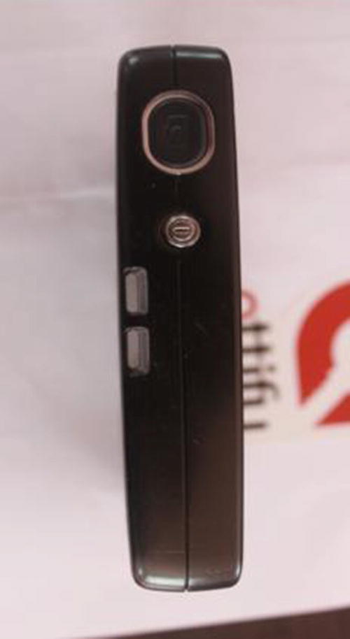
Side view of the Navman system with the power and click buttons
Top view of the Navman system with volume buttons and headphone jack
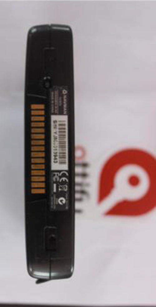
Bottom view exposing a docking container
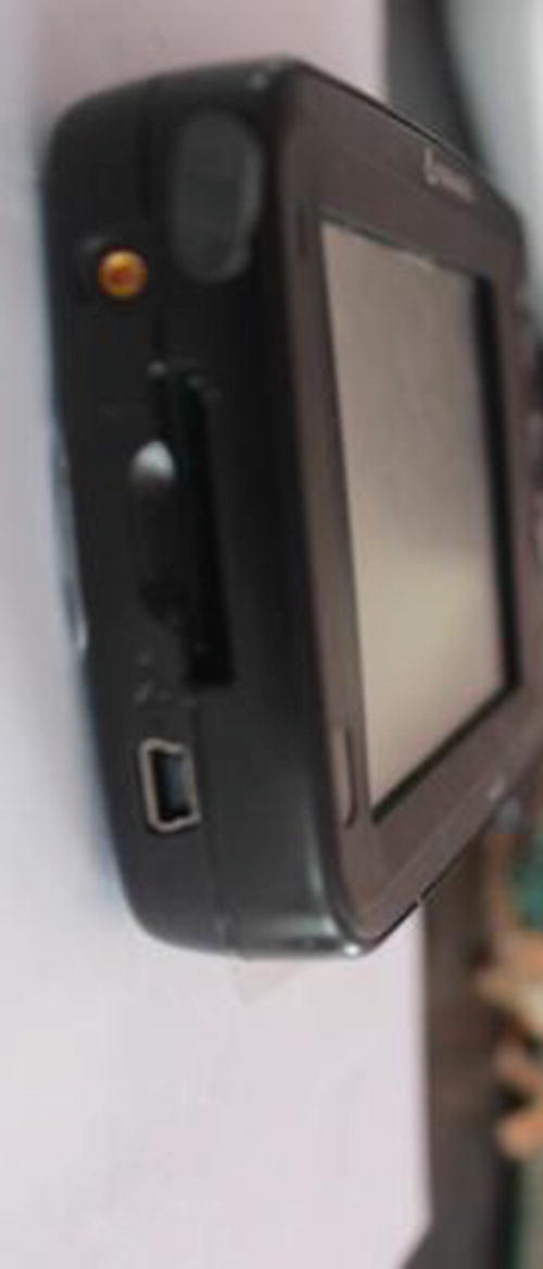
SD card slot, GPS antenna port, and USB port
This is how we perform a visual exterior inspection of a given IoT device. Remember, this is only the first step in analyzing the hardware. To perform a good inspection, you need to analyze both exterior and interior components along with creating an attack surface map as discussed in Chapter 2 .
Internal Inspection
After the exterior inspection, we move on to an internal inspection. As the name suggests, this involves opening the device and looking at its internal components to better understand the device and identify the possible attack surfaces.
To open the device, we need to unscrew the screws. IoT devices can have varying types of screws and often a typical screwdriver set will fail to open some of the less common types of screws found in the devices. Make sure that you have a good screwdriver set handy whenever performing IoT exploitation on the device. Also, take special care while opening the device so as not to damage the device and its internal circuitry. One of the most common mistakes I have seen people make is trying to force open the device, which often leads to physical damage to the device, in some cases rendering it nonfunctional.
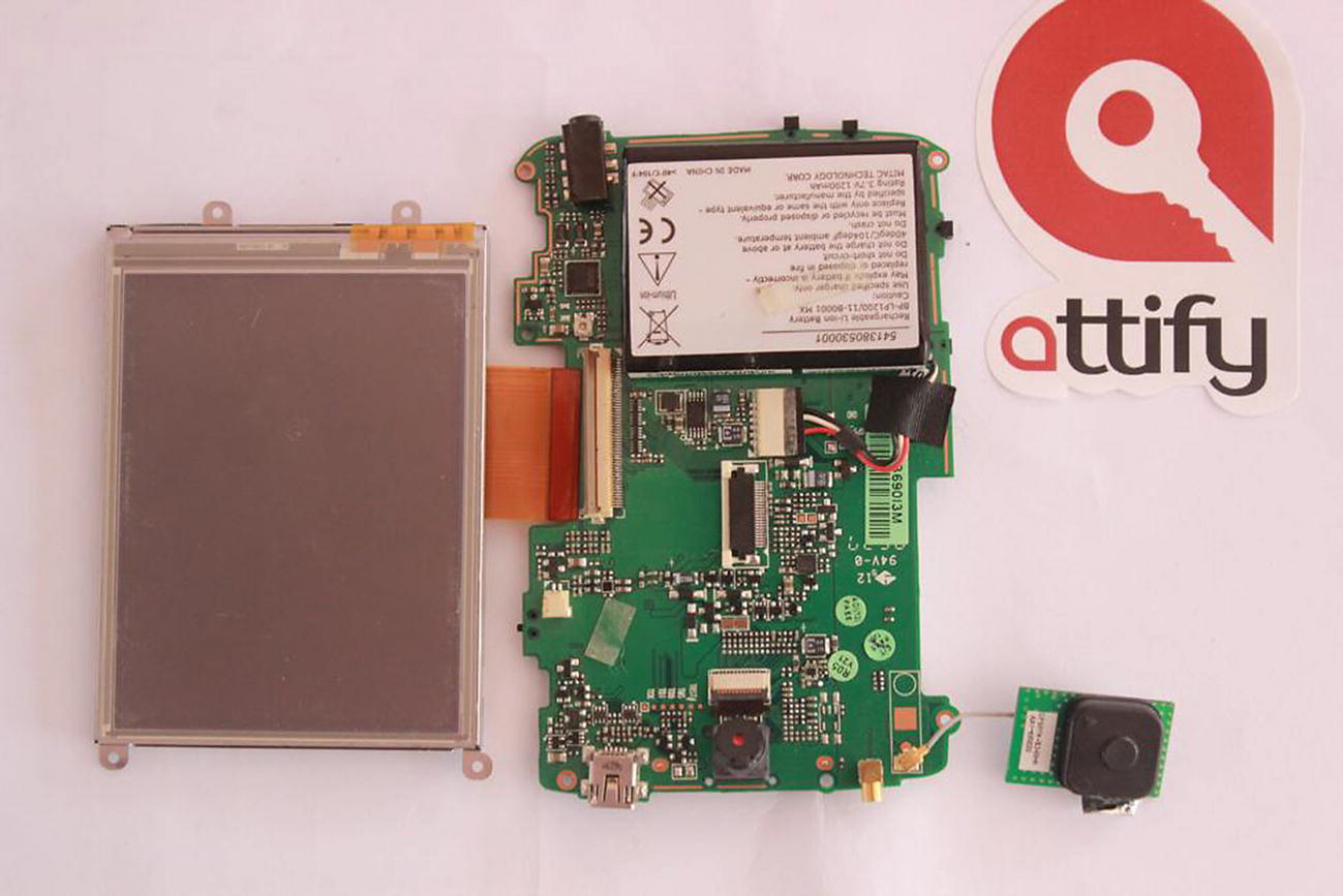
Motherboard and the display that has been removed
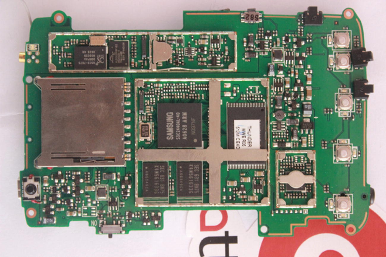
Back side of the circuit board

Close-up of the processor
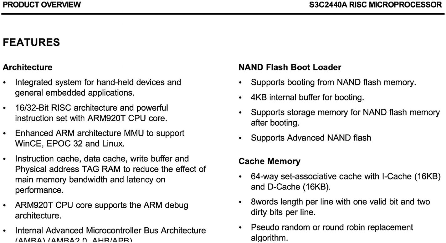
Datasheet for the device
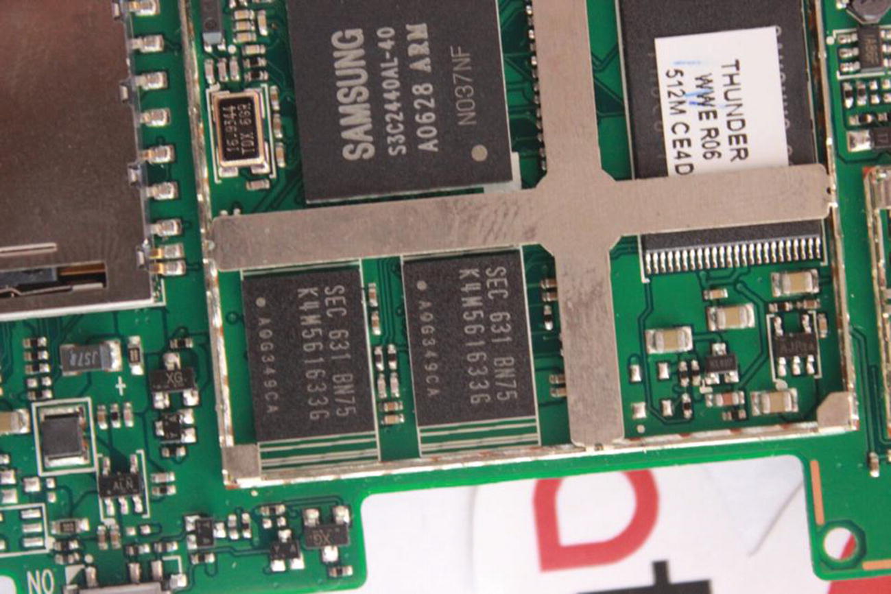
SDRAM and ROM
In Figure 3-10, the components used have the numbers K4M561633G, which by looking online we can see is a 4M × 16Bit × 4 Banks Mobile SDRAM from Future Electronics, and we can also see 512 MB ROM in it.
Continuing on, we can keep looking for different components—identifying their part numbers and then looking them up online to learn more about them. One of the other ways you can identify components is by looking at their logos and checking an online reference catalog such as https://www.westfloridacomponents.com/manufacturer-logos.html .
To look for data sheets, you can either simply search online for the component number or you can visit one of the web sites holding data sheet catalogs such as http://www.alldatasheet.com/ or http://www.datasheets360.com/ .
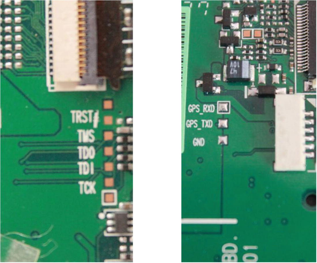
JTAG and UART ports
These interfaces can be found by just looking at the PCB and identifying the Tx and Rx for UART and TRST, TMS, TDO, TDI, and TCK for JTAG, both of which we cover in depth over the upcoming chapters. If you are not familiar with these terms, don’t worry, as this is where we will be spending most of our hardware hacking time in the rest of the book.
Analyzing Data Sheets
Devices might not have a lot of technical information available on their official web site. This is where the FCC ID database comes to the rescue.
If you are an electronics engineer and you would like to dig deeper into the device and maybe even look at the schematics of the device, where do you go? The FCC database is the answer. So, what is the FCC database, you might ask.
What Is FCC ID
The Federal Communication Commission (FCC) is a general body to regulate various devices emitting radio communications (which is most IoT devices). The reason for the regulation is that the radio spectrum is limited and there are devices operating at different frequencies.
In case of no regulatory body, one can decide to manufacture and choose his or her device to use a frequency that might already be in use by another device and lead to interference in the communications of other equipment.
Thus, any device that uses radio communication must go through a set of approval processes, which involves several tests, after which approval is granted by FCC for the device. The FCC ID of a device will be the same for a given model of a specific manufacturer. However, an important thing to note is that the FCC ID is not a permission to transmit, rather just approval by a U.S. government regulatory agency.
You can find the FCC ID of the device either printed on the device itself or by looking online at different sources. Also, don’t get confused with the devices that simply comply with the FCC regulations, as those might not require an FCC ID, given that they don’t communicate wirelessly and just generate small amounts of unintentional radio noise.
The information for the testing process is available on the FCC’s web site, unless the manufacturer specifically asks for a confidentiality request for the document. You can search for a device’s information by providing its FCC ID, either on the official FCC web site located at https://apps.fcc.gov/oetcf/eas/reports/GenericSearch.cfm or via a third-party unofficial web site such as fccid.io or fcc.io.
Using the FCC ID to Find Device Information
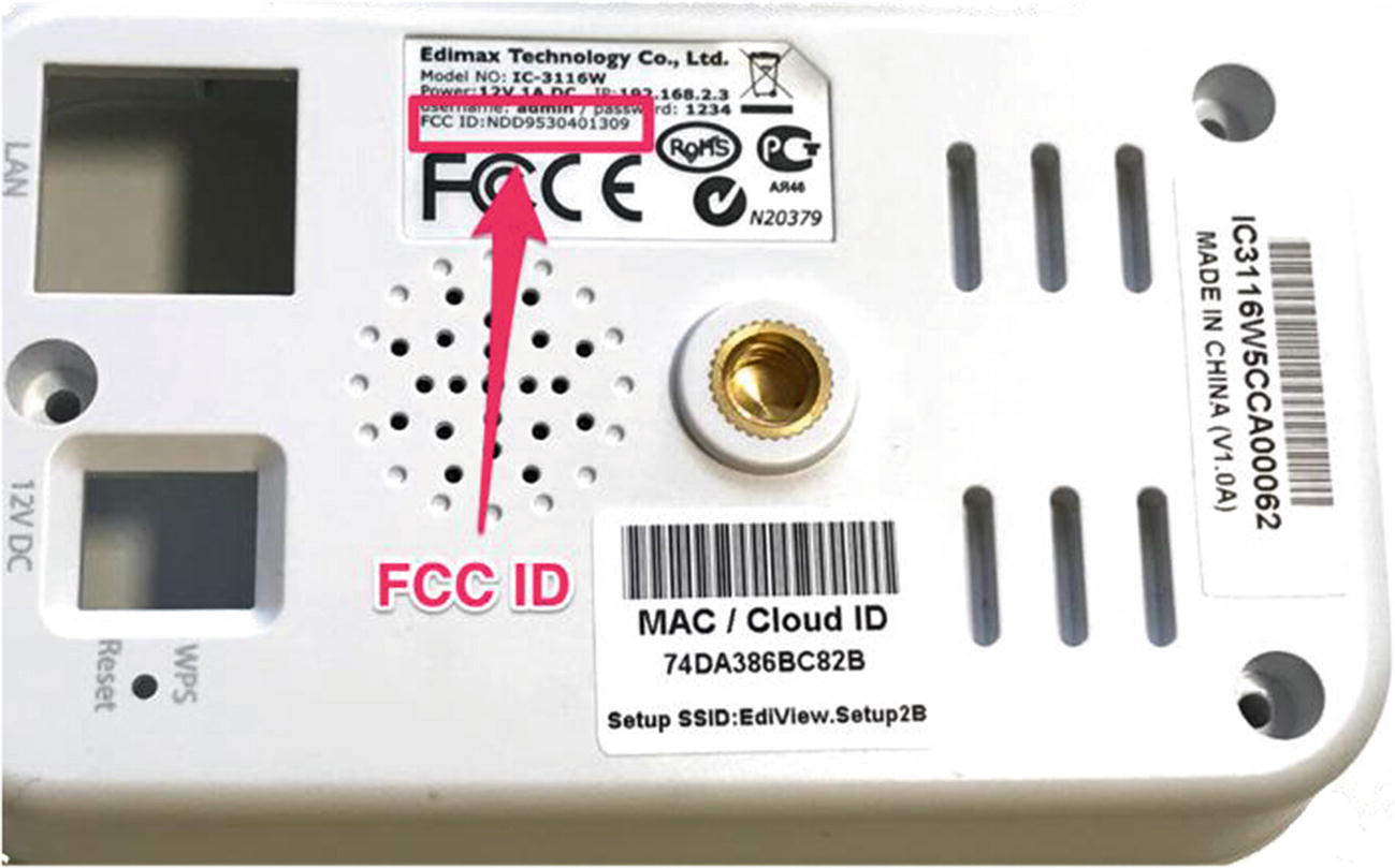
Let’s get hold of a real commercial device and use the FCC ID to find information about the device. In this case, we will use the device Edimax 3116W, which is an IP camera controllable by both mobile and web applications.
Edimax IP camera
FCC ID of Edimax IP camera
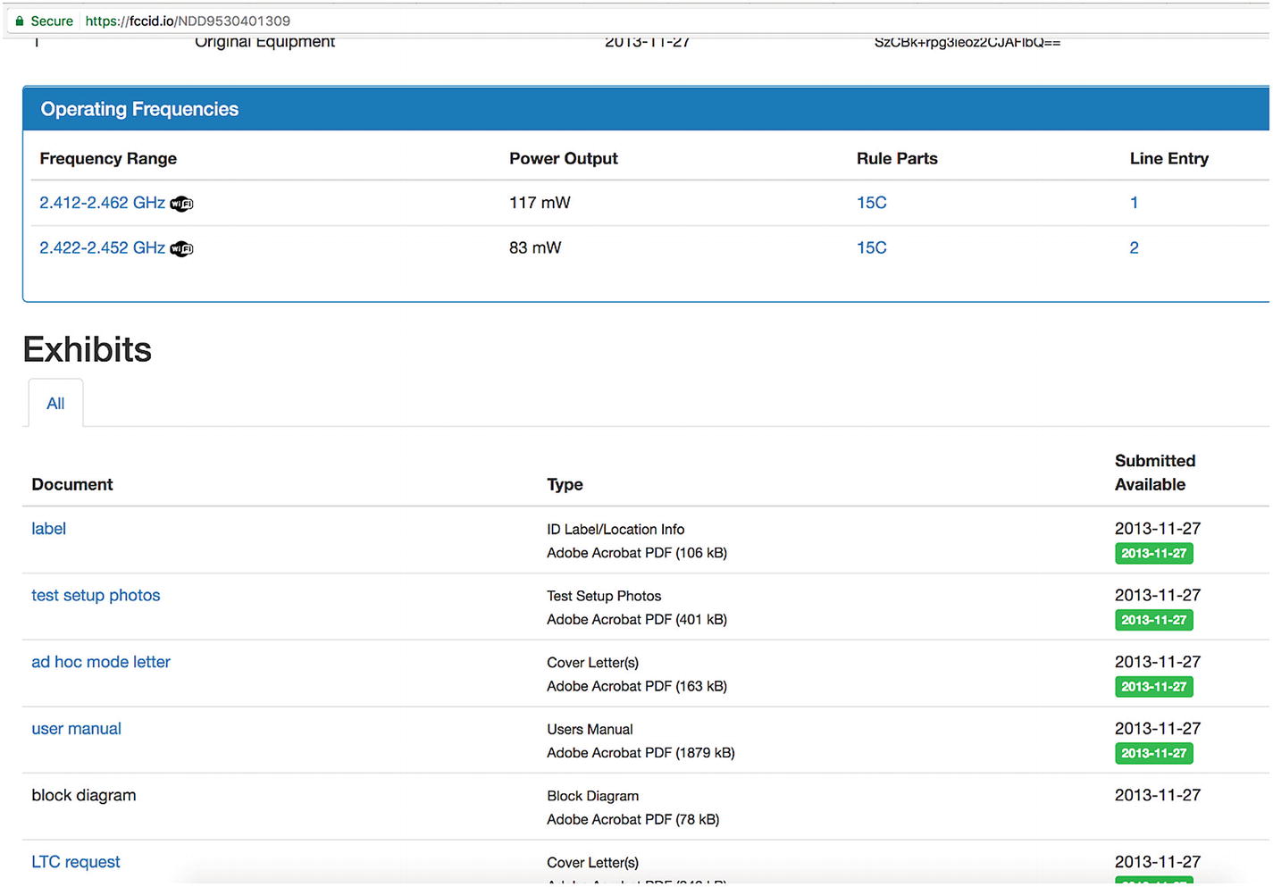
On the web site, we can see various information about the device, such as the frequency range, access to lab setup, internal pictures, external pictures, user manual, Power of Attorney (PoA), and more.
One of the most interesting things to look at while analyzing the FCC ID information is the internal pictures of the device. You can find these at https://fccid.io/document.php?id=2129020 .

Internal pictures from FCC ID revealing the UART interface
Thus, as we can see, FCC IDs can be a goldmine of information and can help us learn a lot of details about the device and its workings.
Another interesting fun fact to know is that sometimes the manufacturer fails to ask for a confidentiality request on a device’s sensitive information, such as the schematics of the device. Access to the schematic of the device is extremely useful as it tells us what the different electronic components are that are used to build the device, and helps us understand the device in much greater depth.
Component Package
One of the things worth mentioning, whenever we discuss embedded or hardware analysis, is the packaging type. Whenever you look at a device’s interior, you will see a number of different components. Each of the components will vary in size, shape, and other aspects based on the device’s characteristic and functionality.
- 1.DIL
- a.
Single in-line package
- b.
Dual in-line package
- c.
TO-220
- a.
- 2.SMD
- a.
CERPACK
- b.
BGA
- c.
SOT-23
- d.
QFP
- e.
SOIC
- f.
SOP
- a.
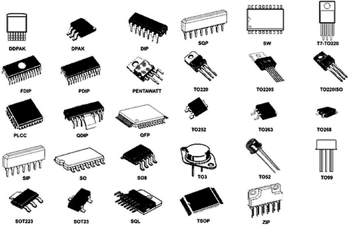
Different IC package types (Source: https://learn.sparkfun.com/tutorials/integrated-circuits/ic-packages )
Radio Chipsets
One of the additional important things you could look for in devices is the various radio chipsets that are present. These chipsets can give you an idea of what kind of communication methodologies a given device uses, even if it is not documented or mentioned anywhere.
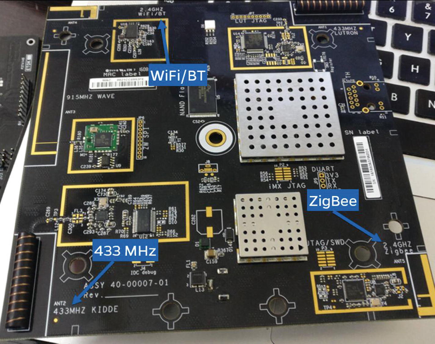
Wink Hub radio chips
Conclusion
We explore additional hardware components in detail as we go further in this book. However, for a in-depth knowledge of various hardware components, I highly recommend you have a look at the book Hardware Hacking by Nicholas Collins, available at http://www.nicolascollins.com/texts/originalhackingmanual.pdf .